Turbocharger
A turbocharger, or colloquially turbo, is a turbine-driven forced induction device that increases an internal combustion engine's efficiency and power output by forcing extra air into the combustion chamber.[1][2] This improvement over a naturally aspirated engine's power output is due to the fact that the compressor can force more air—and proportionately more fuel—into the combustion chamber than atmospheric pressure (and for that matter, ram air intakes) alone.
Turbochargers were originally known as turbosuperchargers when all forced induction devices were classified as superchargers. Nowadays the term "supercharger" is usually applied only to mechanically driven forced induction devices. The key difference between a turbocharger and a conventional supercharger is that a supercharger is mechanically driven by the engine, often through a belt connected to the crankshaft, whereas a turbocharger is powered by a turbine driven by the engine's exhaust gas. Compared to a mechanically driven supercharger, turbochargers tend to be more efficient, but less responsive. Twincharger refers to an engine with both a supercharger and a turbocharger.
Turbochargers are commonly used on truck, car, train, aircraft, and construction equipment engines. They are most often used with Otto cycle and Diesel cycle internal combustion engines. They have also been found useful in automotive fuel cells.[3]
History
Forced induction dates from the late 19th century, when Gottlieb Daimler patented the technique of using a gear-driven pump to force air into an internal combustion engine in 1885.[4] The turbocharger was invented by Swiss engineer Alfred Büchi (1879–1959), the head of Diesel engine research at Gebrüder Sulzer (now called Sulzer), engine manufacturing company in Winterthur,[5] who received a patent in 1905 for using a compressor driven by exhaust gases to force air into an internal combustion engine to increase power output, but it took another 20 years for the idea to come to fruition.[6][7] During World War I French engineer Auguste Rateau fitted turbochargers to Renault engines powering various French fighters with some success.[8] In 1918, General Electric engineer Sanford Alexander Moss attached a turbocharger to a V12 Liberty aircraft engine. The engine was tested at Pikes Peak in Colorado at 14,000 ft (4,300 m) to demonstrate that it could eliminate the power loss usually experienced in internal combustion engines as a result of reduced air pressure and density at high altitude.[8] General Electric called the system turbosupercharging.[9] At the time, all forced induction devices were known as superchargers. However, more recently the term "supercharger" is usually applied to only mechanically driven forced induction devices.
Turbochargers were first used in production aircraft engines such as the Napier Lioness[10] in the 1920s, although they were less common than engine-driven centrifugal superchargers. Ships and locomotives equipped with turbocharged diesel engines began appearing in the 1920s. Turbochargers were also used in aviation, most widely used by the United States. During World War II, notable examples of U.S. aircraft with turbochargers include the B-17 Flying Fortress, B-24 Liberator, P-38 Lightning, and P-47 Thunderbolt. The technology was also used in experimental fittings by a number of other manufacturers, notably a variety of Focke-Wulf Fw 190 models, but the need for advanced high-temperature metals in the turbine kept them out of widespread use.
Turbochargers are widely used in car and commercial vehicles because they allow smaller-capacity engines to have improved fuel economy, reduced emissions, higher power and considerably higher torque.
Turbocharging versus supercharging
In contrast to turbochargers, superchargers are mechanically driven by the engine.[11] Belts, chains, shafts, and gears are common methods of powering a supercharger, placing a mechanical load on the engine.[12][13] For example, on the single-stage single-speed supercharged Rolls-Royce Merlin engine, the supercharger uses about 150 horsepower (110 kilowatts). Yet the benefits outweigh the costs; for the 150 hp (110 kW) to drive the supercharger the engine generates an additional 400-horsepower, a net gain of 250 hp (190 kW). This is where the principal disadvantage of a supercharger becomes apparent; the engine must withstand the net power output of the engine plus the power to drive the supercharger.
Another disadvantage of some superchargers is lower adiabatic efficiency as compared to turbochargers (especially Roots-type superchargers). Adiabatic efficiency is a measure of a compressor's ability to compress air without adding excess heat to that air. Even under ideal conditions, the compression process always results in elevated output temperature; however, more efficient compressors produce less excess heat. Roots superchargers impart significantly more heat to the air than turbochargers. Thus, for a given volume and pressure of air, the turbocharged air is cooler, and as a result denser, containing more oxygen molecules, and therefore more potential power than the supercharged air. In practical application the disparity between the two can be dramatic, with turbochargers often producing 15% to 30% more power based solely on the differences in adiabatic efficiency (however, due to heat transfer from the hot exhaust, considerable heating does occur).
By comparison, a turbocharger does not place a direct mechanical load on the engine, although turbochargers place exhaust back pressure on engines, increasing pumping losses.[11] This is more efficient, because while the increased back pressure taxes the piston exhaust stroke, much of the energy driving the turbine is provided by the still-expanding exhaust gas that would otherwise be wasted as heat through the tailpipe. In contrast to supercharging, the primary disadvantage of turbocharging is what is referred to as "lag" or "spool time". This is the time between the demand for an increase in power (the throttle being opened) and the turbocharger(s) providing increased intake pressure, and hence increased power.
Throttle lag occurs because turbochargers rely on the buildup of exhaust gas pressure to drive the turbine. In variable output systems such as automobile engines, exhaust gas pressure at idle, low engine speeds, or low throttle is usually insufficient to drive the turbine. Only when the engine reaches sufficient speed does the turbine section start to spool up, or spin fast enough to produce intake pressure above atmospheric pressure.
A combination of an exhaust-driven turbocharger and an engine-driven supercharger can mitigate the weaknesses of both.[14] This technique is called twincharging.
In the case of Electro-Motive Diesel's two-stroke engines, the mechanically assisted turbocharger is not specifically a twincharger, as the engine uses the mechanical assistance to charge air only at lower engine speeds and startup. Once above notch # 5, the engine uses true turbocharging. This differs from a turbocharger that uses the compressor section of the turbo-compressor only during starting and, as a two-stroke engines cannot naturally aspirate, and, according to SAE definitions, a two-stroke engine with a mechanically assisted compressor during idle and low throttle is considered naturally aspirated.
Operating principle
In normally aspirated piston engines, intake gases are "pushed" into the engine by atmospheric pressure filling the volumetric void caused by the downward stroke of the piston[15][16] (which creates a low-pressure area), similar to drawing liquid using a syringe. The amount of air actually inspired, compared to the theoretical amount if the engine could maintain atmospheric pressure, is called volumetric efficiency.[17] The objective of a turbocharger is to improve an engine's volumetric efficiency by increasing density of the intake gas (usually air) allowing more power per engine cycle.
The turbocharger's compressor draws in ambient air and compresses it before it enters into the intake manifold at increased pressure.[18] This results in a greater mass of air entering the cylinders on each intake stroke. The power needed to spin the centrifugal compressor is derived from the kinetic energy of the engine's exhaust gases.[19]
A turbocharger may also be used to increase fuel efficiency without increasing power.[20] This is achieved by recovering waste energy in the exhaust and feeding it back into the engine intake. By using this otherwise wasted energy to increase the mass of air, it becomes easier to ensure that all fuel is burned before being vented at the start of the exhaust stage. The increased temperature from the higher pressure gives a higher Carnot efficiency.
The control of turbochargers has changed dramatically over the 100-plus years of its use. Modern turbochargers can use wastegates, blow-off valves and variable geometry, as discussed in later sections.
The reduced density of intake air is often compounded by the loss of atmospheric density seen with elevated altitudes. Thus, a natural use of the turbocharger is with aircraft engines. As an aircraft climbs to higher altitudes, the pressure of the surrounding air quickly falls off. At 18,000 feet (5,500 m), the air is at half the pressure of sea level, which means that the engine produces less than half-power at this altitude.[21]
Pressure increase (or boost)
In automotive applications, boost refers to the amount by which intake manifold pressure exceeds atmospheric pressure. This is representative of the extra air pressure that is achieved over what would be achieved without the forced induction. The level of boost may be shown on a pressure gauge, usually in bar, psi or possibly kPa.[21]
In aircraft engines, turbocharging is commonly used to maintain manifold pressure as altitude increases (i.e. to compensate for lower-density air at higher altitudes). Since atmospheric pressure reduces as the aircraft climbs, power drops as a function of altitude in normally aspirated engines. Systems that use a turbocharger to maintain an engine's sea-level power output are called turbo-normalized systems. Generally, a turbo-normalized system attempts to maintain a manifold pressure of 29.5 inches of mercury (100 kPa).[21]
In petrol engine turbocharger applications, boost pressure is limited to keep the entire engine system, including the turbocharger, inside its thermal and mechanical design operating range. Over-boosting an engine frequently causes damage to the engine in a variety of ways including pre-ignition, overheating, and over-stressing the engine's internal hardware.
For example, to avoid engine knocking (also known as detonation) and the related physical damage to the engine, the intake manifold pressure must not get too high, thus the pressure at the intake manifold of the engine must be controlled by some means. Opening the wastegate allows the excess energy destined for the turbine to bypass it and pass directly to the exhaust pipe, thus reducing boost pressure. The wastegate can be either controlled manually (frequently seen in aircraft) or by an actuator (in automotive applications, it is often controlled by the engine control unit).
Turbocharger lag
Turbocharger lag (turbo lag) is the time required to change power output in response to a throttle change, noticed as a hesitation or slowed throttle response when accelerating as compared to a naturally aspirated engine. This is due to the time needed for the exhaust system and turbocharger to generate the required boost which can also be referred to as spooling. Inertia, friction, and compressor load are the primary contributors to turbocharger lag. Superchargers do not suffer this problem, because the turbine is eliminated due to the compressor being directly powered by the engine.
Turbocharger applications can be categorized into those that require changes in output power (such as automotive) and those that do not (such as marine, aircraft, commercial automotive, industrial, engine-generators, and locomotives). While important to varying degrees, turbocharger lag is most problematic in applications that require rapid changes in power output. Engine designs reduce lag in a number of ways:
- Lowering the rotational inertia of the turbocharger by using lower radius parts and ceramic and other lighter materials
- Changing the turbine's aspect ratio
- Increasing upper-deck air pressure (compressor discharge) and improving wastegate response
- Reducing bearing frictional losses, e.g., using a foil bearing rather than a conventional oil bearing
- Using variable-nozzle or twin-scroll turbochargers
- Decreasing the volume of the upper-deck piping
- Using multiple turbochargers sequentially or in parallel
- Using an antilag system
- Using a turbocharger spool valve to increase exhaust gas flow speed to the (twin-scroll) turbine
Boost threshold
The boost threshold of a turbocharger system is the lower bound of the region within which the compressor operates. Below a certain rate of flow, a compressor produces insignificant boost. This limits boost at a particular RPM, regardless of exhaust gas pressure. Newer turbocharger and engine developments have steadily reduced boost thresholds.
Electrical boosting ("E-boosting") is a new technology under development. It uses an electric motor to bring the turbocharger up to operating speed quicker than possible using available exhaust gases.[22] An alternative to e-boosting is to completely separate the turbine and compressor into a turbine-generator and electric-compressor as in the hybrid turbocharger. This makes compressor speed independent of turbine speed. In 1981, a similar system that used a hydraulic drive system and overspeed clutch arrangement accelerated the turbocharger of the MV Canadian Pioneer (Doxford 76J4CR engine).
Turbochargers start producing boost only when a certain amount of kinetic energy is present in the exhaust gasses. Without adequate exhaust gas flow to spin the turbine blades, the turbocharger cannot produce the necessary force needed to compress the air going into the engine. The boost threshold is determined by the engine displacement, engine rpm, throttle opening, and the size of the turbocharger. The operating speed (rpm) at which there is enough exhaust gas momentum to compress the air going into the engine is called the "boost threshold rpm". Reducing the "boost threshold rpm" can improve throttle response.
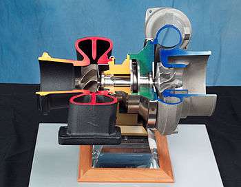
Key components
The turbocharger has three main components:
- The turbine, which is almost always a radial inflow turbine (but is almost always a single-stage axial inflow turbine in large Diesel engines)
- The compressor, which is almost always a centrifugal compressor
- The center housing/hub rotating assembly
Many turbocharger installations use additional technologies, such as wastegates, intercooling and blow-off valves.
Turbine
Energy provided for the turbine work is converted from the enthalpy and kinetic energy of the gas. The turbine housings direct the gas flow through the turbine as it spins at up to 250,000 rpm.[23][24] The size and shape can dictate some performance characteristics of the overall turbocharger. Often the same basic turbocharger assembly is available from the manufacturer with multiple housing choices for the turbine, and sometimes the compressor cover as well. This lets the balance between performance, response, and efficiency be tailored to the application.
The turbine and impeller wheel sizes also dictate the amount of air or exhaust that can flow through the system, and the relative efficiency at which they operate. In general, the larger the turbine wheel and compressor wheel the larger the flow capacity. Measurements and shapes can vary, as well as curvature and number of blades on the wheels.
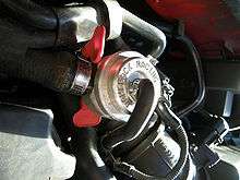
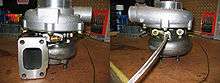 On the left, the brass oil drain connection. On the right are the braided oil supply line and water coolant line connections. |
 Compressor impeller side with the cover removed. |
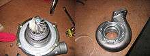 Turbine side housing removed. |
A turbocharger’s performance is closely tied to its size.[25] Large turbochargers take more heat and pressure to spin the turbine, creating lag at low speed. Small turbochargers spin quickly, but may not have the same performance at high acceleration.[26][27] To efficiently combine the benefits of large and small wheels, advanced schemes are used such as twin-turbochargers, twin-scroll turbochargers, or variable-geometry turbochargers.
Twin-turbo
Twin-turbo or bi-turbo designs have two separate turbochargers operating in either a sequence or in parallel.[28][29] In a parallel configuration, both turbochargers are fed one-half of the engine’s exhaust. In a sequential setup one turbocharger runs at low speeds and the second turns on at a predetermined engine speed or load.[29] Sequential turbochargers further reduce turbo lag, but require an intricate set of pipes to properly feed both turbochargers.[28]
Two-stage variable twin-turbos employ a small turbocharger at low speeds and a large one at higher speeds. They are connected in a series so that boost pressure from one turbocharger is multiplied by another, hence the name "2-stage." The distribution of exhaust gas is continuously variable, so the transition from using the small turbocharger to the large one can be done incrementally.[30] Twin turbochargers are primarily used in Diesel engines.[29] For example, in Opel bi-turbo Diesel, only the smaller turbocharger works at low speed, providing high torque at 1,500–1,700 rpm. Both turbochargers operate together in mid range, with the larger one pre-compressing the air, which the smaller one further compresses. A bypass valve regulates the exhaust flow to each turbocharger. At higher speed (2,500 to 3,000 RPM) only the larger turbocharger runs.[31]
Smaller turbochargers have less turbo lag than larger ones, so often two small turbochargers are used instead of one large one. This configuration is popular in engines over 2,500 CCs and in V-shape or boxer engines.[28]
Twin-scroll
Twin-scroll or divided turbochargers have two exhaust gas inlets and two nozzles, a smaller sharper angled one for quick response and a larger less angled one for peak performance.
With high-performance camshaft timing, exhaust valves in different cylinders can be open at the same time, overlapping at the end of the power stroke in one cylinder and the end of exhaust stroke in another. In twin-scroll designs, the exhaust manifold physically separates the channels for cylinders that can interfere with each other, so that the pulsating exhaust gasses flow through separate spirals (scrolls). With common firing order 1-3-4-2, two scrolls of unequal length pair cylinders 1-4 and 3-2. This lets the engine efficiently use exhaust scavenging techniques, which decreases exhaust gas temperatures and NOx emissions, improves turbine efficiency, and reduces turbo lag evident at low engine speeds.[32]
-
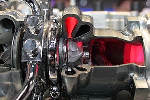
Cut-out of a twin-scroll turbocharger, with two differently angled nozzles
-
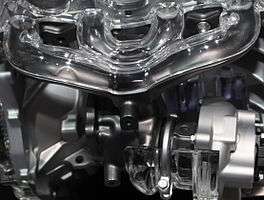
Cut-out of a twin-scroll exhaust and turbine; the dual "scrolls" pairing cylinders 1, 4 and 2, 3 are clearly visible
Variable-geometry
Variable-geometry or variable-nozzle turbochargers use moveable vanes to adjust the air-flow to the turbine, imitating a turbocharger of the optimal size throughout the power curve.[25][26] The vanes are placed just in front of the turbine like a set of slightly overlapping walls. Their angle is adjusted by an actuator to block or increase air flow to the turbine.[26][27] This variability maintains a comparable exhaust velocity and back pressure throughout the engine’s rev range. The result is that the turbocharger improves fuel efficiency without a noticeable level of turbocharger lag.[25]
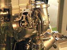 Garrett variable-geometry turbocharger on DV6TED4 engine |
Compressor
The compressor increases the mass of intake air entering the combustion chamber. The compressor is made up of an impeller, a diffuser and a volute housing.
The operating range of a compressor is described by the "compressor map".
Ported shroud
The flow range of a turbocharger compressor can be increased by allowing air to bleed from a ring of holes or a circular groove around the compressor at a point slightly downstream of the compressor inlet (but far nearer to the inlet than to the outlet).
The ported shroud is a performance enhancement that allows the compressor to operate at significantly lower flows. It achieves this by forcing a simulation of impeller stall to occur continuously. Allowing some air to escape at this location inhibits the onset of surge and widens the operating range. While peak efficiencies may decrease, high efficiency may be achieved over a greater range of engine speeds. Increases in compressor efficiency result in slightly cooler (more dense) intake air, which improves power. This is a passive structure that is constantly open (in contrast to compressor exhaust blow off valves, which are mechanically or electronically controlled). The ability of the compressor to provide high boost at low rpm may also be increased marginally (because near choke conditions the compressor draws air inward through the bleed path). Ported shrouds are used by many turbocharger manufacturers.
Center housing/hub rotating assembly
The center hub rotating assembly (CHRA) houses the shaft that connects the compressor impeller and turbine. It also must contain a bearing system to suspend the shaft, allowing it to rotate at very high speed with minimal friction. For instance, in automotive applications the CHRA typically uses a thrust bearing or ball bearing lubricated by a constant supply of pressurized engine oil. The CHRA may also be considered "water-cooled" by having an entry and exit point for engine coolant. Water-cooled models use engine coolant to keep lubricating oil cooler, avoiding possible oil coking (destructive distillation of engine oil) from the extreme heat in the turbine. The development of air-foil bearings removed this risk.
Ball bearings designed to support high speeds and temperatures are sometimes used instead of fluid bearings to support the turbine shaft. This helps the turbocharger accelerate more quickly and reduces turbo lag.[33] Some variable nozzle turbochargers use a rotary electric actuator, which uses a direct stepper motor to open and close the vanes, rather than pneumatic controllers that operate based on air pressure.[34]
Additional technologies commonly used in turbocharger installations
Intercooling

When the pressure of the engine's intake air is increased, its temperature also increases. In addition, heat soak from the hot exhaust gases spinning the turbine will also heat the intake air. The warmer the intake air, the less dense, and the less oxygen available for the combustion event, which reduces volumetric efficiency. Not only does excessive intake-air temperature reduce efficiency, it also leads to engine knock, or detonation, which is destructive to engines.
Turbocharger units often make use of an intercooler (also known as a charge air cooler), to cool down the intake air. Intercoolers are often tested for leaks during routine servicing, particularly in trucks where a leaking intercooler can result in a 20% reduction in fuel economy.
(Note that intercooler is the proper term for the air cooler between successive stages of boost, whereas charge air cooler is the proper term for the air cooler between the boost stage(s) and the appliance that consumes the boosted air.)
Water injection
An alternative to intercooling is injecting water into the intake air to reduce the temperature. This method has been used in automotive and aircraft applications.
Fuel-air mixture ratio
In addition to the use of intercoolers, it is common practice to add extra fuel to the intake air (known as "running an engine rich") for the sole purpose of cooling. The amount of extra fuel varies, but typically reduces the air-fuel ratio to between 11 and 13, instead of the stoichiometric 14.7 (in petrol engines). The extra fuel is not burned (as there is insufficient oxygen to complete the chemical reaction), instead it undergoes a phase change from atomized (liquid) to gas. This phase change absorbs heat, and the added mass of the extra fuel reduces the average thermal energy of the charge and exhaust gas. Even when a catalytic converter is used, the practice of running an engine rich increases exhaust emissions.
Wastegate
A wastegate regulates the exhaust gas flow that enters the exhaust-side driving turbine and therefore the air intake into the manifold and the degree of boosting. It can be controlled by a boost pressure assisted, generally vacuum hose attachment point diaphragm (for vacuum and positive pressure to return commonly oil contaminated waste to the emissions system) to force the spring-loaded diaphragm to stay closed until the overboost point is sensed by the ecu or a solenoid operated by the engine’s electronic control unit or a boost controller, but most production vehicles use a single vacuum hose attachment point spring-loaded diaphragm that can alone be pushed open, thus limiting overboost ability due to exhaust gas pressure forcing open the wastegate.
Anti-surge/dump/blow off valves
Turbocharged engines operating at wide open throttle and high rpm require a large volume of air to flow between the turbocharger and the inlet of the engine. When the throttle is closed, compressed air flows to the throttle valve without an exit (i.e., the air has nowhere to go).
In this situation, the surge can raise the pressure of the air to a level that can cause damage. This is because if the pressure rises high enough, a compressor stall occurs—stored pressurized air decompresses backward across the impeller and out the inlet. The reverse flow back across the turbocharger makes the turbine shaft reduce in speed more quickly than it would naturally, possibly damaging the turbocharger.
To prevent this from happening, a valve is fitted between the turbocharger and inlet, which vents off the excess air pressure. These are known as an anti-surge, diverter, bypass, turbo-relief valve, blow-off valve (BOV), or dump valve. It is a pressure relief valve, and is normally operated by the vacuum from the intake manifold.
The primary use of this valve is to maintain the spinning of the turbocharger at a high speed. The air is usually recycled back into the turbocharger inlet (diverter or bypass valves), but can also be vented to the atmosphere (blow off valve). Recycling back into the turbocharger inlet is required on an engine that uses a mass-airflow fuel injection system, because dumping the excessive air overboard downstream of the mass airflow sensor causes an excessively rich fuel mixture—because the mass-airflow sensor has already accounted for the extra air that is no longer being used. Valves that recycle the air also shorten the time needed to re-spool the turbocharger after sudden engine deceleration, since load on the turbocharger when the valve is active is much lower than if the air charge vents to atmosphere.
Free floating
A free floating turbocharger is the simplest type of turbocharger.[35] This configuration has no wastegate and can’t control its own boost levels.[35][36] They are typically designed to attain maximum boost at full throttle. Free floating turbochargers produce more horsepower because they have less backpressure, but are not driveable in performance applications without an external wastegate.[35][36]
Applications
Petrol-powered cars
The first turbocharged passenger car was the Oldsmobile Jetfire option on the 1962–1963 F85/Cutlass, which used a turbocharger mounted to a 215 cu in (3.52 L) all aluminum V8. Also in 1962, Chevrolet introduced a special run of turbocharged Corvairs, initially called the Monza Spyder (1962–1964) and later renamed the Corsa (1965–1966), which mounted a turbocharger to its air cooled flat six cylinder engine. This model popularized the turbocharger in North America—and set the stage for later turbocharged models from Porsche on the 1975-up 911/930, Saab on the 1978–1984 Saab 99 Turbo, and the very popular 1978–1987 Buick Regal/T Type/Grand National. Today, turbocharging is common on both Diesel and gasoline-powered cars. Turbocharging can increase power output for a given capacity[37] or increase fuel efficiency by allowing a smaller displacement engine. The 'Engine of the year 2011' is an engine used in a Fiat 500 equipped with an MHI turbocharger. This engine lost 10% weight, saving up to 30% in fuel consumption while delivering the same HP (105) as an 1.4 litre engine.
Diesel-powered cars
The first production turbocharger Diesel passenger car was the Garrett-turbocharged[38] Mercedes 300SD introduced in 1978.[39][40] Today, most automotive Diesels are turbocharged, since the use of turbocharging improved efficiency, driveability and performance of Diesel engines,[39][40] greatly increasing their popularity. The Audi R10 with a Diesel engine even won the 24 hours race of Le Mans in 2006, 2007 and 2008.
Motorcycles
The first example of a turbocharged bike is the 1978 Kawasaki Z1R TC.[41] Several Japanese companies produced turbocharged high-performance motorcycles in the early 1980s, such as the CX500 Turbo from Honda- a transversely mounted, liquid cooled V-Twin also available in naturally aspirated form. Since then, few turbocharged motorcycles have been produced. This is partially due to an abundance of larger displacement, naturally aspirated engines being available that offer the torque and power benefits of a smaller displacement engine with turbocharger, but do return more linear power characteristics. The Dutch manufacturer EVA motorcycles builds a small series of turbocharged Diesel motorcycle with an 800cc smart CDI engine.
Trucks
The first turbocharged Diesel truck was produced by Schweizer Maschinenfabrik Saurer (Swiss Machine Works Saurer) in 1938.[42]
Aircraft
A natural use of the turbocharger — and its earliest known use for any internal combustion engine, starting with experimental installations in the 1920s — is with aircraft engines. As an aircraft climbs to higher altitudes the pressure of the surrounding air quickly falls off. At 5,486 m (18,000 ft), the air is at half the pressure of sea level and the airframe experiences only half the aerodynamic drag. However, since the charge in the cylinders is pushed in by this air pressure, the engine normally produces only half-power at full throttle at this altitude. Pilots would like to take advantage of the low drag at high altitudes to go faster, but a naturally aspirated engine does not produce enough power at the same altitude to do so.
The table below is used to demonstrate the wide range of conditions experienced. As seen in the table below, there is significant scope for forced induction to compensate for lower density environments.
Daytona Beach Denver Death Valley Colorado State Highway 5 La Rinconada, Peru, elevation 0 m / 0 ft 1,609 m / 5,280 ft -86 m / -282 ft 4,347 m / 14,264 ft 5,100 m / 16,732 ft atm 1.000 0.823 1.010 0.581 0.526 bar 1.013 0.834 1.024 0.589 0.533 psia 14.696 12.100 14.846 8.543 7.731 kPa 101.3 83.40 102.4 58.90 53.30
A turbocharger remedies this problem by compressing the air back to sea-level pressures (turbo-normalizing), or even much higher (turbo-charging), in order to produce rated power at high altitude. Since the size of the turbocharger is chosen to produce a given amount of pressure at high altitude, the turbocharger is oversized for low altitude. The speed of the turbocharger is controlled by a wastegate. Early systems used a fixed wastegate, resulting in a turbocharger that functioned much like a supercharger. Later systems utilized an adjustable wastegate, controlled either manually by the pilot or by an automatic hydraulic or electric system. When the aircraft is at low altitude the wastegate is usually fully open, venting all the exhaust gases overboard. As the aircraft climbs and the air density drops, the wastegate must continuously close in small increments to maintain full power. The altitude at which the wastegate fully closes and the engine still produces full power is the critical altitude. When the aircraft climbs above the critical altitude, engine power output decreases as altitude increases, just as it would in a naturally aspirated engine.
With older supercharged aircraft, the pilot must continually adjust the throttle to maintain the required manifold pressure during ascent or descent. The pilot must also take care to avoid over-boosting the engine and causing damage. In contrast, modern turbocharger systems use an automatic wastegate, which controls the manifold pressure within parameters preset by the manufacturer. For these systems, as long as the control system is working properly and the pilot's control commands are smooth and deliberate, a turbocharger cannot over-boost the engine and damage it.
Yet the majority of World War II engines used superchargers, because they maintained three significant manufacturing advantages over turbochargers, which were larger, involved extra piping, and required exotic high-temperature materials in the turbine and pre-turbine section of the exhaust system. The size of the piping alone is a serious issue; American fighters Vought F4U and Republic P-47 used the same engine, but the huge barrel-like fuselage of the latter was, in part, needed to hold the piping to and from the turbocharger in the rear of the plane. Turbocharged piston engines are also subject to many of the same operating restrictions as gas turbine engines. Pilots must make smooth, slow throttle adjustments to avoid overshooting their target manifold pressure. The fuel/air mixture must often be adjusted far on the rich side of stoichiometric combustion needs to avoid pre-ignition or detonation in the engine when running at high power settings. In systems using a manually operated wastegate, the pilot must be careful not to exceed the turbocharger's maximum rpm. The additional systems and piping increase an aircraft engine's size, weight, complexity and cost. A turbocharged aircraft engine costs more to maintain than a comparable normally aspirated engine. The great majority of World War II American heavy bombers used by the USAF, particularly the Wright R-1820 Cyclone-9 powered B-17 Flying Fortress, and Pratt & Whitney R-1830 Twin Wasp powered Consolidated B-24 Liberator four-engine bombers both used similar models of General Electric-designed turbochargers in service,[43] as did the twin Allison V-1710-engined Lockheed P-38 Lightning American heavy fighter during the war years.
It must be noted that all of the above WWII aircraft engines had mechanically driven superchargers, and the turbosuperchargers (with Intercoolers) were added to achieve desired altitude performance.
Today, most general aviation piston engine powered aircraft are naturally aspirated. Modern aviation piston engines designed to run at high altitudes typically include a turbocharger (either high pressure or turbonormalized) rather than a supercharger. The change in thinking is largely due to economics. Aviation gasoline was once plentiful and cheap, favoring the simple, but fuel-hungry supercharger. As the cost of fuel has increased, the supercharger has fallen out of favor.
Turbocharged aircraft often occupy a performance range between that of normally aspirated piston-powered aircraft and turbine-powered aircraft. Despite the negative points, turbocharged aircraft fly higher for greater efficiency. High cruise flight also allows more time to evaluate issues before a forced landing must be made.
As the turbocharged aircraft climbs, however, the pilot (or automated system) can close the wastegate, forcing more exhaust gas through the turbocharger turbine, thereby maintaining manifold pressure during the climb, at least until the critical pressure altitude is reached (when the wastegate is fully closed), after which manifold pressure falls. With such systems, modern high-performance piston engine aircraft can cruise at altitudes up to 25,000 feet (above which, RVSM certification would be required), where low air density results in lower drag and higher true airspeeds. This allows flying "above the weather". In manually controlled wastegate systems, the pilot must take care not to overboost the engine, which causes detonation, leading to engine damage.
Marine and land-based Diesel turbochargers
Turbocharging, which is common on Diesel engines in automobiles, trucks, tractors, and boats is also common in heavy machinery such as locomotives, ships, and auxiliary power generation.
- Turbocharging can dramatically improve an engine's specific power and power-to-weight ratio, performance characteristics that are normally poor in non-turbocharged Diesel engines.
- Diesel engines have no detonation because Diesel fuel is injected at or towards the end of the compression stroke and is ignited solely by the heat of compression of the charge air. Because of this, Diesel engines can use a much higher boost pressure than spark ignition engines, limited only by the engine's ability to withstand the additional heat and pressure.
Turbochargers are also employed in certain two-stroke cycle Diesel engines, which would normally require a Roots blower for aspiration. In this specific application, mainly Electro-Motive Diesel (EMD) 567, 645, and 710 Series engines, the turbocharger is initially driven by the engine's crankshaft through a gear train and an overrunning clutch, thereby providing aspiration for combustion. After combustion has been achieved, and after the exhaust gases have reached sufficient heat energy, the overrunning clutch is automatically disengaged, and the turbo-compressor is thereafter driven exclusively by the exhaust gases. In the EMD application, the turbocharger acts as a compressor for normal aspiration during starting and low power output settings and is used for true turbocharging during medium and high power output settings. This is particularly beneficial at high altitudes, as are often encountered on western U.S. railroads. It is possible for the turbocharger to revert to compressor mode momentarily during commands for large increases in engine power.
Business and adoption
Garrett (now Honeywell), Borg Warner and Mitsubishi Turbocharger are the largest manufacturers in Europe and the United States.[2][44][45] Several factors are expected to contribute to more widespread consumer adoption of turbochargers, especially in the US:[46][47]
- New government fuel economy and emissions targets.[44][45]
- Increasing oil prices and a consumer focus on fuel efficiency.
- Only 10 percent of light vehicles sold in the United States are equipped with turbochargers, making the United States an emerging market, compared to 50 percent of vehicles in Europe that are turbocharged Diesel and 27 percent that are gasoline boosted.[48]
- Higher temperature tolerances for gasoline engines, ball bearings in the turbine shaft and variable geometry have reduced driveability concerns.
By 2016, 40 percent of light vehicles sold in the U.S. are expected to be turbocharged.[46][47] In Europe about 65 percent of vehicles are turbocharged, which is expected to grow to 85 percent by 2015.[47] Historically, more than 90 percent of turbochargers were Diesel, however, adoption in gasoline engines is increasing.[47] Honeywell predicts the number of turbochargers in passenger vehicles in the U.S. to more than double to 23 percent by 2016.[48]
The U.S. Coalition for Advanced Diesel Cars is pushing for a technology neutral policy for government subsidies of environmentally friendly automotive technology. If successful, government subsidies would be based on the Corporate Average Fuel Economy (CAFE) standards rather than supporting specific technologies like electric cars. Political shifts could drastically change adoption projections.[49] Turbocharger sales in the United States increased when the federal government boosted corporate average fuel economy targets to 35.5 mpg by 2016.[50]
Safety
Turbocharger failures and resultant high exhaust temperatures are among the recognized causes of car fires.[51]
See also
- Boost gauge
- Engine downsizing
- Exhaust pulse pressure charging
- Hybrid turbocharger
- Twin-turbo
- Twincharger
- Variable-geometry turbocharger
References
- ↑ Nice, Karim (4 December 2000). "How Turbochargers Work". Auto.howstuffworks.com. Retrieved 1 June 2012.
- 1 2 Archived 26 March 2011 at the Wayback Machine.
- ↑ Baines, Nicholas C. (2005). Fundamentals of Turbocharging. Concepts ETI. ISBN 0-933283-14-8.
- ↑ "History of the Supercharger". Retrieved 30 June 2011.
- ↑ Porsche Turbo: The Full History. Peter Vann. MotorBooks International, 11 July 2004
- ↑ Compressor Performance: Aerodynamics for the User. M. Theodore Gresh. Newnes, 29 March 2001
- ↑ Diesel and gas turbine progress, Volume 26. Diesel Engines, 1960
- 1 2 "Hill Climb". Air & Space Magazine. Retrieved 2 August 2010.
- ↑ "The Turbosupercharger and the Airplane Powerplant.".
- ↑ "Gallery". Picturegallery.imeche.org. Retrieved 9 April 2011.
- 1 2 "HowStuffWorks "What is the difference between a turbocharger and a supercharger on a car\'s engine?"". Auto.howstuffworks.com. 1 April 2000. Retrieved 1 June 2012.
- ↑ "supercharging". Elsberg-tuning.dk. Retrieved 1 June 2012.
- ↑ Chris Longhurst. "The Fuel and Engine Bible: page 5 of 6". Car Bibles. Retrieved 1 June 2012.
- ↑ "How to twincharge an engine". Torquecars.com. Retrieved 1 June 2012.
- ↑ "Four Stroke Engine Basics". Compgoparts.com. Retrieved 1 June 2012.
- ↑ Brain, Marshall (5 April 2000). "HowStuffWorks "Internal Combustion"". Howstuffworks.com. Retrieved 1 June 2012.
- ↑ "Volumetric Efficiency (and the REAL factor: mass airflow)". Epi-eng.com. 18 November 2011. Retrieved 1 June 2012.
- ↑ "Variable-Geometry Turbochargers". Large.stanford.edu. 24 October 2010. Retrieved 1 June 2012.
- ↑ "How Turbo Chargers Work". Conceptengine.tripod.com. Retrieved 1 June 2012.
- ↑ "Effects of Variable Geometry Turbochargers in Increasing Efficiency and Reducing Lag - Thermal Systems". Me1065.wikidot.com. 6 December 2007. doi:10.1243/0954407991526766. Retrieved 1 June 2012.
- 1 2 3 Knuteson, Randy (July 1999). "Boosting Your Knowledge of Turbocharging" (PDF). Aircraft Maintenance Technology. Retrieved 18 April 2012.
- ↑ Parkhurst, Terry. "Turbochargers: an interview with Garrett's Martin Verschoor". Allpar. Retrieved 12 December 2006.
- ↑ Mechanical engineering: Volume 106, Issues 7-12; p.51
- ↑ Popular Science. Detroit's big switch to Turbo Power. Apr 1984.
- 1 2 3 Veltman, Thomas (24 October 2010). "Variable-Geometry Turbochargers". Coursework for Physics 240. Retrieved 17 April 2012.
- 1 2 3 Tan, Paul (16 August 2006). "How does Variable Turbine Geometry work?". PaulTan.com. Retrieved 17 April 2012.
- 1 2 A National Maritime Academy Presentation. Variable Turbine Geometry.
- 1 2 3 Twin-Turbo: Parallel or Sequential. Autozine Technical School.
- 1 2 3 Turbo FAQ. Garrett by Honeywell. Retrieved 17 April 2012.
- ↑ "Turbocharging". Autozine Technical School. Retrieved 16 April 2012.
- ↑ "Insignia BiTurbo Diesel: A New Chapter For Opel Flagship" (Press release). Media.gm.com. 14 February 2012. Retrieved 28 September 2012.
- ↑ Pratte, David. "Twin Scroll Turbo System Design". Modified Magazine. Retrieved 28 September 2012.
- ↑ Nice, Karim. "How Turbochargers Work". Auto.howstuffworks.com. Retrieved 2 August 2010.
- ↑ Hartman, Jeff (15 November 2007). "Turbocharging Performance Handbook". MotorBooks International. Retrieved 17 April 2012.
- 1 2 3 "How Turbocharged Piston Engines Work". TurboKart.com. Retrieved 17 April 2012.
- 1 2 Performance Products Tech Info.htm "GT Turbo Basics" Check
|url=value (help). Retrieved 17 April 2012. - ↑ Richard Whitehead (25 May 2010). "Road Test: 2011 Mercedes-Benz CL63 AMG". Thenational.ae. Retrieved 1 June 2012.
- ↑ "Turbocharging Turns 100". Honeywell. 2005. Retrieved 28 September 2012.
- 1 2 "The history of turbocharging". En.turbolader.net. 27 October 1959. Retrieved 1 June 2012.
- 1 2 http://www.theturboforums.com/turbotech/main.htm
- ↑ Smith, Robert (January–February 2013). "1978 Kawasaki Z1R-TC: Turbo Power". Motorcycle Classics. 8 (3). Retrieved 7 February 2013.
- ↑ "BorgWarner turbo history". Turbodriven.com. Retrieved 2 August 2010.
- ↑ White, Graham (1995). Allied Aircraft Piston Engines of World War II. Airlife Publishing. p. 192. ISBN 1-85310-734-4.
It is a little appreciated fact that the General Electric turbosupercharger was key to the Army Air Corps and Army Air Force long-range high-altitude strategic bombing strategy for World War II. All [US] four-engine bombers were fitted with them.
- 1 2 Kitamura, Makiko (24 July 2008). "IHI Aims to Double Turbocharger Sales by 2013 on Europe Demand". Bloomberg. Retrieved 1 June 2012.
- 1 2 CLEPA CEO Lars Holmqvist is retiring (18 November 2002). "Turbochargers - European growth driven by spread to small cars". Just-auto.com. Retrieved 1 June 2012.
- 1 2 Walsh, Dustin (20 November 2011). "Lights, cameras, interaction". Crain’s Detroit Business. Retrieved 23 November 2011.
- 1 2 3 4 Kahl, Martin (3 November 2010). "Interview: David Paja, VP, Global Marketing and Craig Balis, VP, Engineering Honeywell Turbo" (PDF). Automotive World. Retrieved 11 November 2011.
- 1 2 Macaluso, Grace (28 November 2011). "Turbo engines fuel industry's 'quiet revolution'". The Gazette. Retrieved 28 November 2011.
- ↑ "U.S. Coalition for Advanced Diesel Cars Calls for Technology Neutral Public Policies and Regulations". MotorVehicleRegs.com. 9 December 2011. Retrieved 25 January 2012.
- ↑ "Turbo title: Honeywell or BorgWarner?". Automotive News. 24 March 2011. Retrieved 19 November 2011.
- ↑ Why Trucks Catch Fire. Australian Road Transport Suppliers Association. November 2006. Retrieved 3 December 2013.
External links
| Wikimedia Commons has media related to Turbochargers. |
- Don Sherman (February 2006). "Happy 100th Birthday to the Turbocharger". Automobile Magazine.
- NASA Oil Free Turbocharger
- Video showing how a turbocharger works