Poppet valve

A poppet valve (also called mushroom valve[1]) is a valve typically used to control the timing and quantity of gas or vapour flow into an engine.
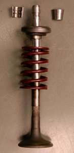
It consists of a hole, usually round or oval, and a tapered plug, usually a disk shape on the end of a shaft also called a valve stem. The portion of the hole where the plug meets with it is referred to as the 'seat' or 'valve seat'. The shaft guides the plug portion by sliding through a valve guide. In exhaust applications a pressure differential helps to seal the valve and in intake valves a pressure differential helps open it. Poppet valves date from at least the 1770s, when James Watt used them on his steam engines.[2]
Etymology
The word poppet shares etymology with "puppet": it is from the Middle English popet ("youth" or "doll"), from Middle French poupette, which is a diminutive of poupe. The use of the word poppet to describe a valve comes from the same word applied to marionettes, which – like the poppet valve – move bodily in response to remote motion transmitted linearly.[3][4] In the past, "puppet valve" was a synonym for poppet valve;[5][6] however, this usage of "puppet" is now obsolete.
Operation
The poppet valve is fundamentally different from slide and oscillating valves; instead of sliding or rocking over a seat to uncover a port, the poppet valve lifts from the seat with a movement perpendicular to the plane of the port. The main advantage of the poppet valve is that it has no movement on the seat, thus requiring no lubrication.[7]
In most cases it is beneficial to have a "balanced poppet" in a direct-acting valve. Less force is needed to move the poppet because all forces on the poppet are nullified by equal and opposite forces. The solenoid coil has to counteract only the spring force[8]
Applications
Poppet valves are used in many industrial processes, from controlling the flow of milk to isolating sterile air in the semiconductor industry. However, they are most well known for their use in internal combustion and steam engines, as described below.
Presta and Schrader valves used on pneumatic tyres are examples of poppet valves. The Presta valve has no spring and relies on a pressure differential for opening and closing while being inflated.
Poppet valves are employed extensively in the launching of torpedoes from submarines. Many systems use compressed air to expel the torpedo from the tube, and the poppet valve recovers large quantity of this air (along with a significant amount of seawater) in order to reduce the tell-tale cloud of bubbles that might otherwise betray the boat's submerged position.[9]
Internal combustion engine
Poppet valves are used in most piston engines to open and close the intake and exhaust ports in the cylinder head. The valve is usually a flat disk of metal with a long rod known as the 'valve stem' attached to one side.
The stem is used to push down on the valve and open it, with a spring generally used to return it to the closed position when the stem is not being depressed. At high revolutions per minute (RPM), the inertia of the spring makes it too slow to return the valve to its seat between cycles, leading to 'valve float'. In this situation desmodromic valves are used which, being closed by a positive mechanical action instead of by a spring, are able to cycle at the high speeds required in, for instance, motorcycle and auto racing engines .
The engine normally operates the valves by pushing on the stems with cams and cam followers. The shape and position of the cam determines the valve lift and when and how quickly (or slowly) the valve is opened. The cams are normally placed on a fixed camshaft which is then geared to the crankshaft, running at half crankshaft speed in a four-stroke engine. On high-performance engines, the camshaft is movable and the cams have a varying height, so by axially moving the camshaft in relation with the engine RPM, also the valve lift varies. See variable valve timing.
For certain applications the valve stem and disk are made of different steel alloys, or the valve stems may be hollow and filled with sodium to improve heat transport and transfer. Although better heat conductors, aluminium cylinder heads require steel valve seat inserts, while cast iron cylinder heads often used integral valve seats in the past. Because the valve stem extends into lubrication in the cam chamber, it must be sealed against blow-by to prevent cylinder gases from escaping into the crankcase, even though the stem to valve clearance is very small, typically 0.04-0.06 mm, a rubber lip-type seal ensures that excessive amounts of oil are not drawn in from the crankcase on the induction stroke and that exhaust gas does not enter the crankcase on the exhaust stroke. Worn valve guides or defective oil seals are characterised by a puff of blue smoke from the exhaust when releasing the accelerator pedal after allowing the engine to overrun and there is high manifold vacuum, such as when changing gears.
In multi-valve engines more than one intake valve and one exhaust valve per cylinder is used to improve engine performance.
Valve position
In very early engine designs the valves were 'upside down' in the block, parallel to the cylinders - the so-called L-head engine because of the shape of the cylinder and combustion chamber, also called 'flathead engine' as the top of the cylinder head is flat. Although this design makes for simplified and cheap construction, it has two major drawbacks; the tortuous path followed by the intake charge limits air flow and effectively prevents speeds greater than 3600 RPM,[10] and the travels of the exhaust through the block can cause overheating under sustained heavy load. This design evolved into 'Intake Over Exhaust', IOE or F-head, where the intake valve was in the head and the exhaust valve was in the block; later both valves moved to the head.
In most such designs the camshaft remained relatively near the crankshaft, and the valves were operated through pushrods and rocker arms. This led to significant energy losses in the engine, but was simpler, especially in a V engine where one camshaft can actuate the valves for both cylinder banks; for this reason, pushrod engine designs have persisted longer in these configurations than others.
More modern designs have the camshaft on top of the cylinder head, pushing directly on the valve stem (again through cam followers, also known as tappets), a system known as overhead camshaft; if there is just one camshaft, this is a single overhead cam or SOHC engine. Often there are two camshafts, one for the intake and one for exhaust valves, creating the dual overhead cam, or DOHC. The camshaft is driven by the crankshaft - through gears, a chain or a timing belt.
Valve wear
In the early days of engine building, the poppet valve was a major problem. Metallurgy was not what it is today, and the rapid opening and closing of the valves against the cylinder heads led to rapid wear. They would need to be re-ground every two years or so by a process known as a 'valve job'. Adding tetraethyllead to the petrol reduced this problem to some degree, as the lead would coat the valve seats, in effect lubricating the metal. In more modern vehicles and properly machined older engines, valve seats may be made of improved alloys such as stellite and the valves themselves may be made of stainless steel. These improvements have generally made this problem disappear completely and made leaded fuel unnecessary.
Valve burn (overheating) is another major problem. It causes excessive valve wear and defective sealing, as well as engine knocking. It can be solved by valve cooling systems that use water or oil as a coolant. In high performance or turbo charged engines sometimes sodium filled valve stems are used. These valve stems then act as a heat pipe. A major cause of burnt valves is a lack of valve clearance at the tappet, meaning the valve cannot completely close. This removes its ability to conduct heat to the cylinder head via the seat, and also forces extremely hot combustion gases between the valve and the seat. Burnt valves will cause a low compression in the affected cylinder and loss of power.
Steam engine
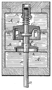
James Watt was using poppet valves to control the flow of steam into the cylinders of his beam engines in the 1770s. A sectional illustration of Watt's beam engine of 1774 using the device is found in Thurston 1878:98,[2] and Lardner (1840) provides an illustrated description of Watt's use of the poppet valve.[11]
When used in high-pressure applications, for example, as admission valves on steam engines, the same pressure that helps seal poppet valves also contributes significantly to the force required to open them. This has led to the development of the balanced poppet or double beat valve, in which two valve plugs ride on a common stem, with the pressure on one plug largely balancing the pressure on the other.[12][13] In these valves, the force needed to open the valve is determined by the pressure and the difference between the areas of the two valve openings. Sickels patented a valve gear for double-beat poppet valves in 1842. Criticism was reported in the journal Science in 1889 of equilibrium poppet valves (called by the article the 'double or balanced or American puppet valve') in use for paddle steamer engines, that by its nature it must leak 15 percent.[14]
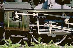
Poppet valves have been used on steam locomotives, often in conjunction with Lentz or Caprotti valve gear. British examples include:
- LNER Class B12
- LNER Class D49
- LNER Class P2
- LMS Stanier Class 5 4-6-0
- BR standard class 5
- BR standard class 8 71000 Duke of Gloucester.
Sentinel Waggon Works used poppet valves in their steam wagons and steam locomotives. Reversing was achieved by a simple sliding camshaft system.
Many locomotives in France, particularly those rebuilt to the designs of Andre Chapelon, such as the SNCF 240P, used Lentz oscillating-cam poppet valves, which were operated by the Walschaert valve gear the locomotives were already equipped with.
The poppet valve was also used on the American Pennsylvania Railroad's T1 duplex locomotives, although the valves commonly failed because the locomotives were commonly operated in excess of 160 km/h (100 mph), and the valves were not meant for the stresses of such speeds. The poppet valves also gave the locomotive a distinctive "chuffing" sound.
See also
References
- ↑ A.L. Dyke (1921), Dyke's Automobile and Gasoline Encyclopedia
- 1 2 Thurston, R.H. (1878). A History of the Growth of the Steam Engine. New York: Appleton & Co. p. 98.
- ↑ "'''Poppet''' at Merriam-Webster". Merriam-webster.com. Retrieved 2011-12-06.
- ↑ "'''Puppet''' at Merriam-Webster". Merriam-webster.com. Retrieved 2011-12-06.
- ↑ "'''Puppet valve''' from 1913 Webster's dictionary". Websters-online-dictionary.org. Retrieved 2011-12-06.
- ↑ "U.S. Patent No. 339809, "Puppet Valve", issued April 13, 1886". Patimg1.uspto.gov. Retrieved 2011-12-06.
- ↑ Fessenden, Charles H. (1915). Valve Gears. New York: McGraw Hill. pp. 159–168.
- ↑ Wahl, Philipp (2013). Piston spool valves and poppet valves. Esslingen: Festo AG & Co. KG.
- ↑ Torpedo Tube Manual https://books.google.com/books?id=-oAVAgAAQBAJ&pg=PA63&lpg=PA63&dq=poppet+valve+torpedo&source=bl&ots=sFId7gUss-&sig=WbdzrI7eoVvnua_Dg6QqNUQUFrI&hl=en&sa=X&ei=j7RwU-eaNpKCogTj4oCgCg&ved=0CEsQ6AEwCA#v=onepage&q=poppet%20valve%20torpedo&f=false
- ↑ "A Handy Guide to Clinton Engines" (PDF). 1956. p. 2. Retrieved October 2, 2015.
R. P. M. 2200 - 3600
- ↑ Lardner, Dionysius (1840). The steam engine explained and illustrated. London: Taylor and Walton. pp. 189–91.
- ↑ Jaques Mouchly, Valve and Valve Gear for Locomotives and Other Engines, U.S. Patent 1,824,830, issued Sept. 29, 1931.
- ↑ Herman G. Mueller, Steam Engine Valve, U.S. Patent 1,983,803, issued Dec. 11, 1934.
- ↑ Criticism by E.N. Dickerson in lecture to the Electric Club of New York 17/01/1889, reported by Science vol.13 No.314, Feb 8 1889 p.95 http://www.sciencemag.org/content/ns-13/314/94.full.pdf