Crankshaft

A crankshaft—related to crank—is a mechanical part able to perform a conversion between reciprocating motion and rotational motion. In a reciprocating engine, it translates reciprocating motion of the piston into rotational motion; whereas in a reciprocating compressor, it converts the rotational motion into reciprocating motion. In order to do the conversion between two motions, the crankshaft has "crank throws" or "crankpins", additional bearing surfaces whose axis is offset from that of the crank, to which the "big ends" of the connecting rods from each cylinder attach.
It is typically connected to a flywheel to reduce the pulsation characteristic of the four-stroke cycle, and sometimes a torsional or vibrational damper at the opposite end, to reduce the torsional vibrations often caused along the length of the crankshaft by the cylinders farthest from the output end acting on the torsional elasticity of the metal.

History
Roman Empire
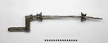
A Roman iron crank of yet unknown purpose dating to the 2nd century AD was excavated in Augusta Raurica, Switzerland. The 82.5 cm long piece has fitted to one end a 15 cm long bronze handle, the other handle being lost.[1][2]
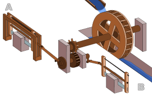
The earliest evidence, anywhere in the world, for a crank and connecting rod in a machine appears in the late Roman Hierapolis sawmill from the 3rd century AD and two Roman stone sawmills at Gerasa, Roman Syria, and Ephesus, Asia Minor (both 6th century AD).[3] On the pediment of the Hierapolis mill, a waterwheel fed by a mill race is shown transmitting power through a gear train to two frame saws, which cut rectangular blocks by way of some kind of connecting rods and, through mechanical necessity, cranks. The accompanying inscription is in Greek.[4]
The crank and connecting rod mechanisms of the other two archaeologically attested sawmills worked without a gear train.[5][6] In ancient literature, we find a reference to the workings of water-powered marble saws close to Trier, now Germany, by the late 4th century poet Ausonius;[3] about the same time, these mill types seem also to be indicated by the Christian saint Gregory of Nyssa from Anatolia, demonstrating a diversified use of water-power in many parts of the Roman Empire.[7] The three finds push back the date of the invention of the crank and connecting rod back by a full millennium;[3] for the first time, all essential components of the much later steam engine were assembled by one technological culture:
With the crank and connecting rod system, all elements for constructing a steam engine (invented in 1712) — Hero's aeolipile (generating steam power), the cylinder and piston (in metal force pumps), non-return valves (in water pumps), gearing (in water mills and clocks) — were known in Roman times.[8]
Medieval East
Al-Jazari (1136–1206) described a crank and connecting rod system in a rotating machine in two of his water-raising machines.[9] His twin-cylinder pump incorporated a crankshaft,[10] though the device was unnecessarily complex.[11]
In China, the potential of the crank of converting circular motion into reciprocal one never seems to have been fully realized, and the crank was typically absent from such machines until the turn of the 20th century.[12]
Medieval Europe
.jpeg)
The Italian physician Guido da Vigevano (c. 1280−1349), planning for a new crusade, made illustrations for a paddle boat and war carriages that were propelled by manually turned compound cranks and gear wheels (center of image).[13] The Luttrell Psalter, dating to around 1340, describes a grindstone rotated by two cranks, one at each end of its axle; the geared hand-mill, operated either with one or two cranks, appeared later in the 15th century;[14]
Renaissance Europe

The first depictions of the compound crank in the carpenter's brace appear between 1420 and 1430 in various northern European artwork.[15] The rapid adoption of the compound crank can be traced in the works of the Anonymous of the Hussite Wars, an unknown German engineer writing on the state of the military technology of his day: first, the connecting-rod, applied to cranks, reappeared, second, double compound cranks also began to be equipped with connecting-rods and third, the flywheel was employed for these cranks to get them over the 'dead-spot'.[16]
In Renaissance Italy, the earliest evidence of a compound crank and connecting-rod is found in the sketch books of Taccola, but the device is still mechanically misunderstood.[16] A sound grasp of the crank motion involved is demonstrated a little later by Pisanello, who painted a piston-pump driven by a water-wheel and operated by two simple cranks and two connecting-rods.[16]
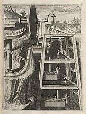
One of the drawings of the Anonymous of the Hussite Wars shows a boat with a pair of paddle-wheels at each end turned by men operating compound cranks (see above). The concept was much improved by the Italian Roberto Valturio in 1463, who devised a boat with five sets, where the parallel cranks are all joined to a single power source by one connecting-rod,[17] an idea also taken up by his compatriot Francesco di Giorgio.[18]
Crankshafts were also described by Konrad Kyeser (d. 1405), Leonardo da Vinci (1452–1519)[9] and a Dutch "farmer" by the name Cornelis Corneliszoon van Uitgeest in 1592. His wind-powered sawmill used a crankshaft to convert a windmill's circular motion into a back-and-forward motion powering the saw. Corneliszoon was granted a patent for his crankshaft in 1597.
From the 16th century onwards, evidence of cranks and connecting rods integrated into machine design becomes abundant in the technological treatises of the period: Agostino Ramelli's The Diverse and Artifactitious Machines of 1588 alone depicts eighteen examples, a number that rises in the Theatrum Machinarum Novum by Georg Andreas Böckler to 45 different machines, one third of the total.[19]
Internal combustion engines


Large engines are usually multicylinder to reduce pulsations from individual firing strokes, with more than one piston attached to a complex crankshaft. Many small engines, such as those found in mopeds or garden machinery, are single cylinder and use only a single piston, simplifying crankshaft design.
A crankshaft is subjected to enormous stresses, potentially equivalent of several tonnes of force. The crankshaft is connected to the fly-wheel (used to smooth out shock and convert energy to torque), the engine block, using bearings on the main journals, and to the pistons via their respective con-rods. An engine loses up to 75% of its generated energy in the form of friction, noise and vibration in the crankcase and piston area. The remaining losses occur in the valvetrain (timing chains, belts, pulleys, camshafts, lobes, valves, seals etc.) heat and blow by.
Bearings
The crankshaft has a linear axis about which it rotates, typically with several bearing journals riding on replaceable bearings (the main bearings) held in the engine block. As the crankshaft undergoes a great deal of sideways load from each cylinder in a multicylinder engine, it must be supported by several such bearings, not just one at each end. This was a factor in the rise of V8 engines, with their shorter crankshafts, in preference to straight-8 engines. The long crankshafts of the latter suffered from an unacceptable amount of flex when engine designers began using higher compression ratios and higher rotational speeds. High performance engines often have more main bearings than their lower performance cousins for this reason.
Piston stroke
The distance the axis of the crank throws from the axis of the crankshaft determines the piston stroke measurement, and thus engine displacement. A common way to increase the low-speed torque of an engine is to increase the stroke, sometimes known as "shaft-stroking." This also increases the reciprocating vibration, however, limiting the high speed capability of the engine. In compensation, it improves the low speed operation of the engine, as the longer intake stroke through smaller valve(s) results in greater turbulence and mixing of the intake charge. Most modern high speed production engines are classified as "over square" or short-stroke, wherein the stroke is less than the diameter of the cylinder bore. As such, finding the proper balance between shaft-stroking speed and length leads to better results.
Engine configuration
The configuration, meaning the number of pistons and their placement in relation to each other leads to straight, V or flat engines. The same basic engine block can sometimes be used with different crankshafts, however, to alter the firing order. For instance, the 90° V6 engine configuration, in older days sometimes derived by using six cylinders of a V8 engine with a 3 throw crankshaft, produces an engine with an inherent pulsation in the power flow due to the "gap" between the firing pulses alternates between short and long pauses because the 90 degree engine block does not correspond to the 120 degree spacing of the crankshaft. The same engine, however, can be made to provide evenly spaced power pulses by using a crankshaft with an individual crank throw for each cylinder, spaced so that the pistons are actually phased 120° apart, as in the GM 3800 engine. While most production V8 engines use four crank throws spaced 90° apart, high-performance V8 engines often use a "flat" crankshaft with throws spaced 180° apart, essentially resulting in two straight four engines running on a common crankcase. The difference can be heard as the flat-plane crankshafts result in the engine having a smoother, higher-pitched sound than cross-plane (for example, IRL IndyCar Series compared to NASCAR Sprint Cup Series, or a Ferrari 355 compared to a Chevrolet Corvette). This type of crankshaft was also used on early types of V8 engines. See the main article on crossplane crankshafts.
Engine balance
For some engines it is necessary to provide counterweights for the reciprocating mass of each piston and connecting rod to improve engine balance. These are typically cast as part of the crankshaft but, occasionally, are bolt-on pieces. While counter weights add a considerable amount of weight to the crankshaft, it provides a smoother running engine and allows higher RPM levels to be reached.
Flying arms

In some engine configurations, the crankshaft contains direct links between adjacent crankpins, without the usual intermediate main bearing. These links are called flying arms.[20] This arrangement is sometimes used in V6 and V8 engines as it enables the engine to be designed with different V angles than what would otherwise be required to create an even firing interval, while still using fewer main bearings than would normally be required with a single piston per crankthrow. This arrangement reduces weight and engine length at the expense of less crankshaft rigidity.
Rotary aircraft engines
Some early aircraft engines were a rotary engine design, where the crankshaft was fixed to the airframe and instead the cylinders rotated with the propeller.
Radial engines
The radial engine is a reciprocating type internal combustion engine configuration in which the cylinders point outward from a central crankshaft like the spokes of a wheel. It resembles a stylized star when viewed from the front, and is called a "star engine" (German Sternmotor, French Moteur en étoile) in some languages. The radial configuration was very commonly used in aircraft engines before turbine engines became predominant.
Construction

Crankshafts can be monolithic (made in a single piece) or assembled from several pieces. Monolithic crankshafts are most common, but some smaller and larger engines use assembled crankshafts.
Forging and casting

Crankshafts can be forged from a steel bar usually through roll forging or cast in ductile steel. Today more and more manufacturers tend to favor the use of forged crankshafts due to their lighter weight, more compact dimensions and better inherent damping. With forged crankshafts, vanadium microalloyed steels are mostly used as these steels can be air cooled after reaching high strengths without additional heat treatment, with exception to the surface hardening of the bearing surfaces. The low alloy content also makes the material cheaper than high alloy steels. Carbon steels are also used, but these require additional heat treatment to reach the desired properties. Iron crankshafts are today mostly found in cheaper production engines (such as those found in the Ford Focus diesel engines) where the loads are lower. Some engines also use cast iron crankshafts for low output versions while the more expensive high output version use forged steel.
Machining
Crankshafts can also be machined out of a billet, often a bar of high quality vacuum remelted steel. Though the fiber flow (local inhomogeneities of the material's chemical composition generated during casting) doesn’t follow the shape of the crankshaft (which is undesirable), this is usually not a problem since higher quality steels, which normally are difficult to forge, can be used. These crankshafts tend to be very expensive due to the large amount of material that must be removed with lathes and milling machines, the high material cost, and the additional heat treatment required. However, since no expensive tooling is needed, this production method allows small production runs without high costs.
In an effort to reduce costs, used crankshafts may also be machined. A good core may often be easily reconditioned by a crankshaft grinding [21] process. Severely damaged crankshafts may also be repaired with a welding operation, prior to grinding, that utilizes a submerged arc welding machine. To accommodate the smaller journal diameters a ground crankshaft has, and possibly an over-sized thrust dimension, undersize engine bearings are used to allow for precise clearances during operation.
Machining or remanufacturing crankshafts are precision machined to exact tolerances with no odd size crankshaft bearings or journals. Thrust surfaces are micro-polished to provide precise surface finishes for smooth engine operation and reduced thrust bearing wear. Every journal is inspected and measured with critical accuracy. After machining, oil holes are chamfered to improve lubrication and every journal polished to a smooth finish for long bearing life. Remanufactured crankshafts are thoroughly cleaned with special emphasis to flushing and brushing out oil passages to remove any contaminants. Typically there are 23 steps to re-manufacturing a crankshaft which are as follows:[22]
Step 1: Industrial cleaning
The first step in the industrial crankshaft remanufacturing process is cleaning the entire crankshaft. Machine shops soak the rebuilt crankshafts in a hot tank and use a power washing station on the overall shaft as needed. Next machinists then wire brush all oil holes to remove caked on residue and other substances.
Step 2: Magnetic particle inspection
The second step in the crankshaft remanufacturing process is using a magnetic particle inspection method to check for cracks. The crankshaft is maganitized and sprayed with a iron oxide powder which, under blacklight conditions, makes any cracks or imperfections visible. All remanufactured crankshafts are checked for imperfections before proceeding forward in the manufacturing process.
Step 3: Check counterweights
The machine shop then removes and cleans the counterweights. The production facility then checks the counterweights to make sure they are tight. If the counterweights are loose a technician then replaces all of the counterweight bolts. Counterweights are inspected for cracks before being replaced or retightened. In step sixteen the machinist re-installs the counterweights back into the rebuilt crankshafts.
Step 4: Check crankshaft bearings and straightness
The machinist then inspects the entire incoming remanufactured crankshaft for damage and determines the size of the journals and mains. Next the machinist checks the hardness of the mains and journals. It is crucial to also inspect the crankshaft bearings and check the straightness of the overall crankshaft. Re-straightening the industrial crankshaft if not up to OEM standards occurs in step seven. Veteran machine shops typically do not re-straighten the rebuilt crankshafts until a quality control technician checks the bolt holes and seals the surface for divots.
Step 5: Check bolt holes
The technician checks the keyway, nose, bolt holes and seals the surface for non-conformities. Usually machine shops will tap bolt holes up to but not more than ½” on all remanufactured crankshafts.
Step 6: Stamp counterweight webbing
The rebuild team next stamps the counterweights & webbing in proper firing order (alpha if numeric & vice versa). Technicians then stamp the employee ID#, Work Order # and date on #1 rod webbing. Stamping this information on the rod webbing helps keep the quality control process order in case of future issues during the manufacturing process.
Step 7: Re-straightening for rebuilt crankshafts
The seventh step is industrial crankshaft re-straightening. If the remanufactured crankshaft is deemed un-straight than technicians use an industrial straightening machine on the crankshaft. The straightening machine determines how many dials are out of line. To re-straighten the shaft technicians heat up the crankshaft to 500-600 degrees. Any more than 700 degrees takes the hardness out of the shaft. The strightener process corrects the bent crankshaft to the proper OEM specifications for rebuilt crankshafts.
Step 8: Repeat magnetic particle inspection process
The eight step in the process is repeating the magnetic particle inspection process if straightening was performed. Anytime metal is being stressed it is imperative to re-inspect for cracks and structural imperfections on the reman crankshaft.
Step 9: Undercutting
The ninth step in the industrial crankshaft re-manufacturing process is undercutting. Technicians undercut the rod or journals to eliminate wear before buildup.
Step 10: Thermal spraying
The tenth step is the prevention of further buildup via metalizing often called thermal spraying. Thermal spraying has been around for well over 100 years but is still widely known as the best preventative corrosion fighting technique in the world. Thermal spraying is also known for changing the surface of the metallic component and is common with rebuilt crankshafts. Thermal spraying involves protrusion of molten particles onto the heated metallic surface where is bonds and forms a smooth coating interwoven into the structure. There are many different types of thermal spray alloys that can be employed for re-manufactured crankshafts. Typically, boron alloys are used as they very dense, hard and are oxide free. They also prevent against abrasive materials that cause divots, scratches and cracks in addition to preventing surface erosion and corrosion. Thermal spray is an important step some machine shops employ, but not always performed in the industry.
Step 11: Industrial crankshaft welding
The welding process for re-manufactured crankshafts is called submerged arc welding. It is a powdered flux plus a weld which combines to produce a more precise weld. The most common flux powder used is called #1 Flux 2245 HD. This powder eliminates the need for technicians to wear weld masking and reduces the amount of dust by-product.
Step 12: Relieve structural stress
The twelfth step is to relieve stress upon the entire rebuilt crankshaft structure by heating it up again to 500-600 degrees.
Step 13: Recheck for straightness
Next step is to check for overall straightness of the re-manufactured crankshaft once again. If the re-manufactured crankshaft is out of alignment then the technician repeats step 7 and re-straighten the structure. Each of the re-manufactured crankshafts is checked multiple times throughout the re-manufacturing process to ensure quality control. If the straightness is not compromised the rebuilt crankshafts can proceed to step thirteen which is crankshaft grinding.
Step 14: Rough crankshaft grinding
This is one of the most important steps in the re-manufacturing process of industrial crankshafts. This step involves rough grinding the excess material from the rod or journals and is known as crankshaft grinding. On the rod there are various mains that need to be reground to proper OEM specifications. These rods are spun grind to the next under-size using the pultrusion crankshaft grinding machine. Rod mains are ground inside and outside. Machine shops have the ability to “crankshaft grind” to any size to bring back the crankshaft to standard OEM specifications.
Step 15: Finished crankshaft grinding
Next the technician performs a finished crankshaft grinding procedure. The finished crankshaft grinding is a more precise grind which reaches the correct OEM specifications. Before the technician starts the crankshaft grinding they should see what crankshaft bearings are available and start from there. For example, the OEM specification for a Caterpillar 3306 Rod is 2.9987” – 3.0003”. Top industrial crankshaft grinding technicians always stop at the high end of the tolerance level. Lastly the technician further refines the crankshaft grinding process in during the micro-polishing process at step eighteen.
Step 16: Shot peening
The next step is to process the industrial crankshaft in using shot peen machinery. Shot peening adds an additional layer of hardness to the re-manufactured crankshaft.
Step 17: Replace or re-tighten counterweights
Step 17 involves replacing the counterweights in proper firing order. Either the new counterweights are installed or the old counterweight bolts are re-tightened and tested.
Step 18: Determine proper balance
The machine shop then determines if the proper rotational balance of the re-manufactured crankshafts is achieved. In the engine the crankshaft, pistons and rods all in a constant rotation. The counterweights are designed to offset the weight of the rod and the pistons in the engine. When in motion the kinetic energy and the sum of all forces should be equal to zero on all moving parts. If the re-manufactured crankshaft counterweights are imbalanced it adds additional stress on other components of the engine. The technician should then make sure the internal balance and the external balance of the crankshaft counterweights are properly aligned.
Step 19: Micro-polishing
Then the technician micro-polishes each of the rebuilt crankshafts by hand. To further refine the crankshaft grinding process the machinist makes the most precise fit by micro-polishing the component with a 600 grit emery cloth. Through micro-polishing and industrial crankshaft grinding, the machine shop achieves the recommended Rockwell hardness and Ra finish (Roughness Parameter).
Step 20: Test reman crankshaft Rockwell hardness
Next the technician checks the industry standard hardness. Industry standards crankshaft hardness is 40 on the Rockwell hardness scale. A 45-50 rating is what most reputable machine shops try to employ for all remanufactured crankshafts. When possible it is wise to go beyond industry standards to prevent any future weaknesses within the unit. Typically, hardness can be reduced if the engine is out of oil or the journal is spun incorrectly.
Step 21: Final quality control inspection
Quality control inspects all of the finished reman crankshafts for internal and external mistakes. A typical quality control department uses separate testing and analytical measurement tools from the technicians to ensure accuracy. If the rebuilt crankshaft passes the quality control inspection it goes onto the rust proofing stage.
Step 22: Rustproof remanufactured crankshaft
The vast majority of machine shops apply rust proofing to all remanufactured crankshafts using Cosmoline, which is standard rust-proofing for engine parts.
Step 23: Packaging
Lastly the machine shop packs the finished rebuilt crankshaft correctly making sure to using proper boxing and damage proof coverings. It is important to cover the rod journals (varies per crankshaft) with paper & tape in place.
Microfinishing
To achieve the required specifications, automotive manufacturers which design and produce high-volume, low-cost powertrain components, strive toward surpassing stringent emissions and efficiency regulations (see Euro 6c standards for reference) to reduce losses. In motorsport, powertrain developers strive to increase power output by reducing weight, using strong metal alloys, hardening crankshafts, improving balance, reducing friction and vibration as previously described.
To achieve the required specifications, automotive and motorsport powertrain designers and manufacturers adopt a process called microfinishing. Microfinishing (or superfinishing) is an engineering function concerned with metrology and tribology. Microfinishing takes place after the crankshaft grinding process, and is used to improve the geometry of the crankshaft journals from waviness, peaks and lapping caused by the grinding process and establish surface roughness as low as Ra = 0.01 µm if required.
Microfinished crankshafts show improved roundness and cylindricity for each main and pin and thrust journal, and where applicable the oil seal journal. Another important function to a geometrically correct shape is to provide it with a specific surface roughness as per design requirements for optimum lubrication hydrodynamics (essential for crankshafts in engines with stop/start fuel saving technology).
Today, crankshafts used in outboard engines, motorbikes, cars, trucks, busses, marine engines and electric generators and racing engines, are all microfinished for optimum performance. They are designed and manufactured to transfer as much energy to the fly-wheel and drivetrain and absorb as much power from the con-rods, as efficiently as possible for as long as possible.
With this new technology, a light weight, turbocharged 2.0 liter, 4 cylinder diesel engine, (with a low-cost 4 pin, 5 main induction hardened, cast steel, microfinished crankshaft), in a small family car, potentially delivers 180 hp and provides an average fuel consumption of 60 miles per gallon and beyond.
Fatigue strength
The fatigue strength of crankshafts is usually increased by using a radius at the ends of each main and crankpin bearing. The radius itself reduces the stress in these critical areas, but since the radius in most cases is rolled, this also leaves some compressive residual stress in the surface, which prevents cracks from forming.
Hardening
Most production crankshafts use induction hardened bearing surfaces, since that method gives good results with low costs. It also allows the crankshaft to be reground without re-hardening. But high performance crankshafts, billet crankshafts in particular, tend to use nitridization instead. Nitridization is slower and thereby more costly, and in addition it puts certain demands on the alloying metals in the steel to be able to create stable nitrides. The advantage of nitridization is that it can be done at low temperatures, it produces a very hard surface, and the process leaves some compressive residual stress in the surface, which is good for fatigue properties. The low temperature during treatment is advantageous in that it doesn’t have any negative effects on the steel, such as annealing. With crankshafts that operate on roller bearings, the use of carburization tends to be favored due to the high Hertzian contact stresses in such an application. Like nitriding, carburization also leaves some compressive residual stresses in the surface.
Counterweights
Some expensive, high performance crankshafts also use heavy-metal counterweights to make the crankshaft more compact. The heavy-metal used is most often a tungsten alloy but depleted uranium has also been used. A cheaper option is to use lead, but compared with tungsten its density is much lower.
Stress on crankshafts
The shaft is subjected to various forces but generally needs to be analysed in two positions. Firstly, failure may occur at the position of maximum bending; this may be at the centre of the crank or at either end. In such a condition the failure is due to bending and the pressure in the cylinder is maximal. Second, the crank may fail due to twisting, so the conrod needs to be checked for shear at the position of maximal twisting. The pressure at this position is the maximal pressure, but only a fraction of maximal pressure.
See also
| Wikimedia Commons has media related to Crankshaft. |
- Bicycle crankset
- Brace (tool)
- Cam
- Camshaft
- Crankcase, the housing that surrounds the crankshaft
- Crankshaft torsional vibration
- Crank (mechanism)
- Hudson Motor Car Company, balanced crankshaft in 1916 allowed higher RPM & more power
- Piston motion equations
- Tunnel crankshaft
References
- 1 2 Schiöler 2009, pp. 113f.
- ↑ Laur-Belart 1988, pp. 51–52, 56, fig. 42
- 1 2 3 4 Ritti, Grewe & Kessener 2007, p. 161:
Because of the findings at Ephesus and Gerasa the invention of the crank and connecting rod system has had to be redated from the 13th to the 6th c; now the Hierapolis relief takes it back another three centuries, which confirms that water-powered stone saw mills were in use when Ausonius wrote his Mosella.
- ↑ Ritti, Grewe & Kessener 2007, pp. 139–141
- ↑ Ritti, Grewe & Kessener 2007, pp. 149–153
- ↑ Mangartz 2010
- ↑ Wilson 2002, p. 16
- ↑ Ritti, Grewe & Kessener 2007, p. 156, fn. 74
- 1 2 Ahmad Y Hassan. The Crank-Connecting Rod System in a Continuously Rotating Machine.
- ↑ Sally Ganchy, Sarah Gancher (2009), Islam and Science, Medicine, and Technology, The Rosen Publishing Group, p. 41, ISBN 1-4358-5066-1
- ↑ White, Jr. 1962, p. 170:
However, that al-Jazari did not entirely grasp the meaning of the crank for joining reciprocating with rotary motion is shown by his extraordinarily complex pump powered through a cog-wheel mounted eccentrically on its axle.
- ↑ White, Jr. 1962, p. 104:
Yet a student of the Chinese technology of the early twentieth century remarks that even a generation ago the Chinese had not 'reached that stage where continuous rotary motion is substituted for reciprocating motion in technical contrivances such as the drill, lathe, saw, etc. To take this step familiarity with the crank is necessary. The crank in its simple rudimentary form we find in the [modern] Chinese windlass, which use of the device, however, has apparently not given the impulse to change reciprocating into circular motion in other contrivances'. In China the crank was known, but remained dormant for at least nineteen centuries, its explosive potential for applied mechanics being unrecognized and unexploited.
- ↑ Hall 1979, p. 80
- ↑ White, Jr. 1962, p. 111
- ↑ White, Jr. 1962, p. 112
- 1 2 3 White, Jr. 1962, p. 113
- ↑ See this illustration (top)
- ↑ White, Jr. 1962, p. 114
- ↑ White, Jr. 1962, p. 172
- ↑ Nunney 2007, pp. 16, 41.
- ↑ "Crankshaft Grinding". Crankshaft Repair.
- ↑ "Remanufactured Crankshafts - Capital Reman Exchange". Capital Reman Exchange. Retrieved 2015-12-28.
Sources
- Hall, Bert S. (1979), The Technological Illustrations of the So-Called "Anonymous of the Hussite Wars". Codex Latinus Monacensis 197, Part 1, Wiesbaden: Dr. Ludwig Reichert Verlag, ISBN 3-920153-93-6
- al-Hassan, Ahmad Y.; Hill, Donald R. (1992), Islamic Technology. An Illustrated History, Cambridge University Press, ISBN 0-521-42239-6
- Laur-Belart, Rudolf (1988), Führer durch Augusta Raurica (5th ed.), Augst
- Mangartz, Fritz (2010), Die byzantinische Steinsäge von Ephesos. Baubefund, Rekonstruktion, Architekturteile, Monographs of the RGZM, 86, Mainz: Römisch-Germanisches Zentralmuseum, ISBN 978-3-88467-149-8
- White, Jr., Lynn (1962), Medieval Technology and Social Change, Oxford: At the Clarendon Press
- Ritti, Tullia; Grewe, Klaus; Kessener, Paul (2007), "A Relief of a Water-powered Stone Saw Mill on a Sarcophagus at Hierapolis and its Implications", Journal of Roman Archaeology, 20: 138–163
- Schiöler, Thorkild (2009), "Die Kurbelwelle von Augst und die römische Steinsägemühle", Helvetia Archaeologica, 40 (159/160), pp. 113–124
- Wilson, Andrew (2002), "Machines, Power and the Ancient Economy", The Journal of Roman Studies, 92, pp. 1–32
- Nunney, Malcolm J. (2007), Light and Heavy Vehicle Technology (4th ed.), Elsevier Butterworth-Heinemann, ISBN 978-0-7506-8037-0
External links
- Interactive crank animation https://www.desmos.com/calculator/8l2kvyivqo
- D & T Mechanisms - Interactive Tools for Teachers (applets) http://www.content.networcs.net/tft/mechanisms.htm
- Grewe, Klaus (2009), "Die Reliefdarstellung einer antiken Steinsägemaschine aus Hierapolis in Phrygien und ihre Bedeutung für die Technikgeschichte. Internationale Konferenz 13.−16. Juni 2007 in Istanbul", in Bachmann, Martin, Bautechnik im antiken und vorantiken Kleinasien (PDF), Byzas (in German), 9, Istanbul: Ege Yayınları/Zero Prod. Ltd., pp. 429–454, ISBN 978-975-807-223-1