Variable valve timing
In internal combustion engines, variable valve timing (VVT) is the process of altering the timing of a valve lift event, and is often used to improve performance, fuel economy or emissions. It is increasingly being used in combination with variable valve lift systems. There are many ways in which this can be achieved, ranging from mechanical devices to electro-hydraulic and camless systems. Increasingly strict emissions regulations are causing many automotive manufacturers to use VVT systems.
Two-stroke engines use a power valve system to get similar results to VVT.
Background theory
The valves within an internal combustion engine are used to control the flow of the intake and exhaust gases into and out of the combustion chamber. The timing, duration and lift of these valve events has a significant impact on engine performance. Without variable valve timing or variable valve lift, the valve timing must be the same for all engine speeds and conditions, therefore compromises are necessary.[1] An engine equipped with a variable valve timing actuation system is freed from this constraint, allowing performance to be improved over the engine operating range.
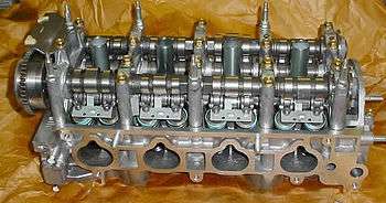
Piston engines normally use valves which are driven by camshafts. The cams open the valves (lift) for a certain amount of time (duration) during each intake and exhaust cycle. The timing of the valve opening and closing is also important. The camshaft is driven by the crankshaft through timing belts, gears or chains.
An engine requires large amounts of air when operating at high speeds. However, the intake valves may close before enough air has entered each combustion chamber, reducing performance. On the other hand, if the camshaft keeps the valves open for longer periods of time, as with a racing cam, problems start to occur at the lower engine speeds. This will cause unburnt fuel to exit the engine since the valves are still open. This leads to lower engine performance and increased emissions.
Continuous versus discrete
Early variable valve timing systems used discrete (stepped adjustment). For example, one timing would be used below 3500 rpm and another used above 3500 rpm.
More advanced "continuous variable valve timing" systems offer continuous (infinite) adjustment of the valve timing. Therefore, the timing can be optimized to suit all engine speeds and conditions.[1][2]
Cam phasing versus variable duration
The simplest form of VVT is cam-phasing, where the angle of a camshaft is rotated forwards or backwards (relative to the crankshaft). Thus the valves open and close earlier or later; however, the camshaft lift and duration cannot be altered with a cam-phasing system.
Achieving variable duration on a VVT system requires a more complex system, such as multiple cam profiles or oscillating cams.
Typical effect of timing adjustments
Late intake valve closing (LIVC) The first variation of continuous variable valve timing involves holding the intake valve open slightly longer than a traditional engine. This results in the piston actually pushing air out of the cylinder and back into the intake manifold during the compression stroke. The air which is expelled fills the manifold with higher pressure, and on subsequent intake strokes the air which is taken in is at a higher pressure. Late intake valve closing has been shown to reduce pumping losses by 40% during partial load conditions, and to decrease nitric oxide (NOx) emissions by 24%. Peak engine torque showed only a 1% decline, and hydrocarbon emissions were unchanged.[2]
Early intake valve closing (EIVC) Another way to decrease the pumping losses associated with low engine speed, high vacuum conditions is by closing the intake valve earlier than normal. This involves closing the intake valve midway through the intake stroke. Air/fuel demands are so low at low-load conditions and the work required to fill the cylinder is relatively high, so Early intake valve closing greatly reduces pumping losses.[2] Studies have shown early intake valve closing reduces pumping losses by 40%, and increases fuel economy by 7%. It also reduced nitric oxide emissions by 24% at partial load conditions. A possible downside to early intake valve closing is that it significantly lowers the temperature of the combustion chamber, which can increase hydrocarbon emissions.[2]
Early intake valve opening Early intake valve opening is another variation that has significant potential to reduce emissions. In a traditional engine, a process called valve overlap is used to aid in controlling the cylinder temperature. By opening the intake valve early, some of the inert/combusted exhaust gas will back flow out of the cylinder, via the intake valve, where it cools momentarily in the intake manifold. This inert gas then fills the cylinder in the subsequent intake stroke, which aids in controlling the temperature of the cylinder and nitric oxide emissions. It also improves volumetric efficiency, because there is less exhaust gas to be expelled on the exhaust stroke.[2]
Early/late exhaust valve closing Early and late exhaust valve closing can also reduce emissions. Traditionally, the exhaust valve opens, and exhaust gas is pushed out of the cylinder and into the exhaust manifold by the piston as it travels upward. By manipulating the timing of the exhaust valve, engineers can control how much exhaust gas is left in the cylinder. By holding the exhaust valve open slightly longer, the cylinder is emptied more and ready to be filled with a bigger air/fuel charge on the intake stroke. By closing the valve slightly early, more exhaust gas remains in the cylinder which increases fuel efficiency. This allows for more efficient operation under all conditions.
Challenges
The main factor preventing this technology from wide use in production automobiles is the ability to produce a cost effective means of controlling the valve timing under the conditions internal to an engine. An engine operating at 3000 revolutions per minute will rotate the camshaft 25 times per second, so the valve timing events have to occur at precise times to offer performance benefits. Electromagnetic and pneumatic camless valve actuators offer the greatest control of precise valve timing, but, in 2016, are not cost effective for production vehicles.
History
Steam engines
The history of the search for a method of variable valve opening duration goes back to the age of steam engines when the valve opening duration was referred to as “steam cut-off”. The Stephenson valve gear, as used on early steam locomotives, supported variable cutoff, that is, changes to the time at which the admission of steam to the cylinders is cut off during the power stroke.
Early approaches to variable cutoff coupled variations in admission cutoff with variations in exhaust cutoff. Admission and exhaust cutoff were decoupled with the development of the Corliss valve. These were widely used in constant speed variable load stationary engines, with admission cutoff, and therefore torque, mechanically controlled by a centrifugal governor and trip valves.
As poppet valves came into use, a simplified valve gear using a camshaft came into use. With such engines, variable cutoff could be achieved with variable profile cams that were shifted along the camshaft by the governor.[3]
Aircraft
An early experimental 200 hp Clerget V-8 from the 1910s used a sliding camshaft to change the valve timing. Some versions of the Bristol Jupiter radial engine of the early 1920s incorporated variable valve timing gear, mainly to vary the inlet valve timing in connection with higher compression ratios.[4] The Lycoming R-7755 engine had a Variable Valve Timing system consisting of two cams that can be selected by the pilot. One for take off, pursuit and escape, the other for economical cruising.
Automotive
The desirability of being able to vary the valve opening duration to match an engine’s rotational speed first became apparent in the 1920s when maximum allowable RPM limits were generally starting to rise. Until about this time an engine’s idle RPM and its operating RPM were very similar, meaning that there was little need for variable valve duration. It was in the 1920s that the first patents for variable duration valve opening started appearing – for example United States patent U.S. Patent 1,527,456.
In 1958 Porsche made application for a German Patent, also applied for and published as British Patent GB861369 in 1959. The Porsche patent used an oscillating cam to increase the valve lift and duration. The desmodromic cam driven via a push/pull rod from an eccentric shaft or swashplate. It is unknown if any working prototype was ever made.
Fiat was the first auto manufacturer to patent a functional automotive variable valve timing system which included variable lift. Developed by Giovanni Torazza in the late 1960s, the system used hydraulic pressure to vary the fulcrum of the cam followers (US Patent 3,641,988).[5] The hydraulic pressure changed according to engine speed and intake pressure. The typical opening variation was 37%.
Alfa Romeo was the first manufacturer to use a variable valve timing system in production cars (US Patent 4,231,330).[6] The fuel injected models of the 1980 Alfa Romeo Spider 2000 had a mechanical VVT system. The system was engineered by Ing Giampaolo Garcea in the 1970s.[7]
In 1989, Honda released the VTEC system.[8] While the earlier Nissan NVCS alters the phasing of the camshaft, VTEC switches to a separate cam profile at high engine speeds to improve peak power. The first VTEC engine Honda produced was the B16A which was installed in the Integra, CRX, and Civic hatchback available in Japan and Europe.
In 1992, Porsche first introduced VarioCam, which was the first system to provide continuous adjustment (all previous systems used discrete adjustment). The system was released in the Porsche 968 and operated on the intake valves only.
Marine
Variable valve timing has begun to trickle down to marine engines. Volvo Penta's VVT marine engine uses a cam phaser, controlled by the ECM, continuously varies advance or retardation of camshaft timing. [9]
Diesel
In 2007, Caterpillar developed the C13 and C15 Acert engines which used VVT technology to reduce NOx emissions, to avoid the use of EGR after 2002 EPA requirements.[10][11]
In 2010, Mitsubishi developed and started mass production of its 4N13 1.8 L DOHC I4, the world's first passenger car diesel engine that features a variable valve timing system.[12][13]
Automotive nomenclature

Manufacturers use many different names to describe their implementation of the various types of variable valve timing systems. These names include:
- AVCS (Subaru)
- AVLS (Subaru)
- CPS (Proton)
- CVTCS (Nissan, Infiniti)
- CVVT (Alfa Romeo, Citroën, Geely, Hyundai, Iran Khodro, Kia, Peugeot, Renault, Volvo)
- DCVCP - dual continuous variable cam phasing (General Motors)
- DVVT (Daihatsu) (Perodua)
- MIVEC (Mitsubishi)
- MultiAir (Fiat)
- N-VCT (Nissan)
- S-VT (Mazda)
- Ti-VCT (Ford)
- VANOS (BMW)
- VarioCam (Porsche)
- VCT (Ford, Yamaha)
- VTEC (Honda, Acura)
- VVC (MG Rover)
- VVL (Nissan)
- Valvelift (Audi)
- VVEL (Nissan, Infiniti)
- VVT (Chrysler, General Motors, Proton, Suzuki, Volkswagen Group)
- VVT-i (Toyota, Lexus)
- VTVT (Hyundai, Kia)
Methods for implementing Variable Valve Control (VVC)
Cam switching
This method uses two cam profiles, with an actuator to swap between the profiles (usually at a specific engine speed). Cam switching can also provide variable valve lift and variable duration, however the adjustment is discrete rather than continuous.
The first production use of this system was Honda's VTEC system. VTEC changes hydraulic pressure to actuate a pin that locks the high lift, high duration rocker arm to an adjacent low lift, low duration rocker arm(s).
Cam phasing
Many production VVT systems are the cam phasing type, using a device known as a variator. This allows continuous adjustment of the cam timing (although many early systems only used discrete adjustment), however the duration and lift cannot be adjusted.
Oscillating cam
These designs use an oscillating or rocking motion in a part cam lobe, which acts on a follower. This follower then opens and closes the valve. Some oscillating cam systems use a conventional cam lobe, while others use an eccentric cam lobe and a connecting rod. The principle is similar to steam engines, where the amount of steam entering the cylinder was regulated by the steam "cut-off" point.
The advantage of this design is that adjustment of lift and duration is continuous.[14] However, in these systems, lift is proportional to duration, so lift and duration cannot be separately adjusted.
The BMW (valvetronic),[15] Nissan (VVEL), and Toyota (valvematic) oscillating cam systems act on the intake valves only.
Eccentric cam drive
Eccentric cam drive systems operates through an eccentric disc mechanism which slows and speeds up the angular speed of the cam lobe during its rotation. Arranging the lobe to slow during its open period is equivalent to lengthening its duration.
The advantage of this system is that duration can be varied independent of lift[16][17] (however this system does not vary lift). The drawback is two eccentric drives and controllers are needed for each cylinder (one for the intake valves and one for the exhaust valves), which increases complexity and cost.
MG Rover is the only manufacturer that has released engines using this system.
Three-dimensional cam lobe
This system consists of a cam lobe that varies along its length[18] (similar to a cone shape). One end of the cam lobe has a short duration/reduced lift profile, and the other end has a longer duration/greater lift profile. In between, the lobe provides a smooth transition between these two profiles. By shifting area of the cam lobe which is in contact with the follower, the lift and duration can be continuously altered. This is achieved by moving the camshaft axially (sliding it across the engine) so a stationary follower is exposed to a varying lobe profile to produce different amounts of lift and duration. The downside to this arrangement is that the cam and follower profiles must be carefully designed to minimise contact stress (due to the varying profile).
Ferrari is commonly associated with this system,[19][20] however it is unknown whether any production models to date have used this system.
Two shaft combined cam lobe profile
This system is not known to be used in any production engines.
It consists of two (closely spaced) parallel camshafts, with a pivoting follower that spans both camshafts and is acted on by two lobes simultaneously. Each camshaft has a phasing mechanism which allows its angular position relative to the engine’s crankshaft to be adjusted. One lobe controls the opening of a valve and the other controls the closing of the same valve, therefore variable duration is achieved through the spacing of these two events.
The drawbacks to this design include:
- At long duration settings, one lobe may be starting to reduce its lift as the other is still increasing. This has the effect of lessening the overall lift and possibly causing dynamic problems. One company claims to have solved the uneven rate of opening of the valve problem to some extent thus allowing long duration at full lift.[21][22][23]
- Size of the system, due to the parallel shafts, the larger followers etc.
Coaxial two shaft combined cam lobe profile
This system is not known to be used in any production engines.
The operating principle is that the one follower spans the pair of closely spaced lobes. Up to the angular limit of the nose radius the follower 'sees' the combined surface of the two lobes as a continuous, smooth surface. When the lobes are exactly aligned the duration is at a minimum (and equal to that of each lobe alone) and when at the extreme extent of their misalignment the duration is at a maximum. The basic limitation of the scheme is that only a duration variation equal to that of the lobe nose true radius (in camshaft degrees or double this value in crankshaft degrees) is possible. In practice this type of variable cam has a maximum range of duration variation of about forty crankshaft degrees.
This is the principle behind what seems to be the very first variable cam suggestion appearing in the USPTO patent files in 1925 (1527456). The "Clemson camshaft" is of this type.[24]
Helical camshaft
Also known as "Combined two shaft coaxial combined profile with helical movement", this system is not known to be used in any production engines.[25][26][27][28]
It has a similar principle to the previous type, and can use the same base duration lobe profile. However instead of rotation in a single plane, the adjustment is both axial and rotational giving a helical or three-dimensional aspect to its movement. This movement overcomes the restricted duration range in the previous type. The duration range is theoretically unlimited but typically would be of the order of one hundred crankshaft degrees, which is sufficient to cover most situations.
The cam is reportedly difficult and expensive to produce, requiring very accurate helical machining and careful assembly.
Camless engines
Engine designs which do not rely on a camshaft to operate the valves have greater flexibility in achieving variable valve timing and variable valve lift. However, there has not been a production camless engine released for road vehicles as yet.
Types of camless engines include:
- electro-mechanical (using electromagnets)
- hydraulic
- stepper motors
- pneumatic
See also
References
- 1 2 Wu, B. (2007). A simulation-based approach for developing optimal calibrations for engines with variable valve actuation. Oil and Gas Science and Technology, 62(4), 539-553.
- 1 2 3 4 5 Hong, H. (2004). Review and analysis of variable valve timing strategies - eight ways to approach. Proceedings of the Institution of Mechanical Engineers, Part D: Journal of Automobile Engineering, 218(10), 1179-1200.
- ↑ "Variable Valve Timing - 1886 - Practical Machinist". Practical Machinist. Retrieved 2010-04-04.
- ↑ Arthur W., Gardiner; William E. Whedon (25 February 1927). "REPORT No. 272: THE RELATIVE PERFORMANCE OBTAINED WITH SEVERAL METHODS OF CONTROL OF AN OVERCOMPRESSED ENGINE USING GASOLINE" (PDF). Langley Aeronautical Laboratory.
- ↑ "VALVE-ACTUATING MECHANISM FOR AN INTERNAL COMBUSTION ENGINE". freepatentsonline.com. Retrieved 2011-01-12.
- ↑ "Timing variator for the timing system of a reciprocating internal combustion engine". freepatentsonline.com. Retrieved 2011-01-12.
- ↑ "Alfa Romeo Spider FAQ" (PDF). alfaspiderfaq.org. Retrieved 2008-11-29.
- ↑ asia.vtec.net
- ↑ "Volvo Penta Variable Valve Timing (VVT)". http://WWW.marineenginedigest.com/. Retrieved 2012-10-27. External link in
|work=(help) - ↑
- ↑ Medium/Heavy Duty Truck Engines, Fuel & Computerized Management Systems
- ↑ "Geneva 2010: Mitsubishi ASX (Outlander Sport) Debuts in Geneva", autoguide.com
- ↑ Mitsubishi Motors UK Geneva motor show 2010 presskit
- ↑ "Autozine VVT Article". Retrieved 17 January 2012.
- ↑ "Autospeed Valvetronic Article". Retrieved 17 January 2012.
- ↑ "Rover VVC Article" (PDF). Retrieved 17 January 2012.
- ↑ "Autozine VVT Article - See Rover VVC Section.". Retrieved 17 January 2012.
- ↑ howstuffworks.com
- ↑ Lumley, John L. (1999). Engines - An Introduction. Cambridge UK: Cambridge University Press. pp. 63–64. ISBN 0-521-64277-9.
- ↑ "HowStuffWorks - Ferrari 3D cam article". Retrieved 17 January 2012.
- ↑ "USPTO 5052350". Retrieved 17 January 2012.
- ↑ "USPTO 5642692". Retrieved 17 January 2012.
- ↑ "Mechadyne VLD" (PDF). Retrieved 17 January 2012.
- ↑ "USPTO 4771742". Retrieved 17 January 2012.
- ↑ "Performance Buildups" Magazine Vol.15 No.1 Pages 30-35 Author: Paul Tuzson
- ↑ "Two Wheels" Magazine July 2008 pages 74-75 Author Jeremy Bowdler
- ↑ "Fast Fours" Magazine July 2004 pages 100-108 Author: Paul Tuzson
- ↑ "USPTO 6832586". Retrieved 17 January 2012.
External links
- Honda Technology Picture Book, VTEC
- Delphi Variable Cam Phasers (VCP)
- Volvo CVVT article
- MG Rover VVC article
- MG Rover VVC article (from sandmuseum.com)
- Mechadyne VVA systems