Radial turbine
A radial turbine is a turbine in which the flow of the working fluid is radial to the shaft. The difference between axial and radial turbines consists in the way the fluid flows through the components (compressor and turbine). Whereas for an axial turbine the rotor is 'impacted' by the fluid flow, for a radial turbine, the flow is smoothly orientated perpendicular to the rotation axis, and it drives the turbine in the same way water drives a watermill. The result is less mechanical stress (and less thermal stress, in case of hot working fluids) which enables a radial turbine to be simpler, more robust, and more efficient (in a similar power range) when compared to axial turbines. When it comes to high power ranges (above 5 MW) the radial turbine is no longer competitive (due to heavy and expensive rotor) and the efficiency becomes similar to that of the axial turbines.

Advantages and challenges
Compared to an axial flow turbine, a radial turbine can employ a relatively higher pressure ratio (≈4) per stage with lower flow rates. Thus these machines fall in the lower specific speed and power ranges. For high temperature applications rotor blade cooling in radial stages is not as easy as in axial turbine stages. Variable angle nozzle blades can give higher stage efficiencies in a radial turbine stage even at off-design point operation. In the family of hydro-turbines, Francis turbine is a very well-known IFR turbine which generates much larger power with a relatively large impeller.
Components of radial turbines
-

Ninety degree inward-flow radial turbine stage
-
_turbine_stage_with_cantilever_blades.jpg)
Velocity triangles for an inward-flow radial (IFR) turbine stage with cantilever blades
The radial and tangential components of the absolute velocity c2 are cr2 and cq2, respectively. The relative velocity of the flow and the peripheral speed of the rotor are w2 and u2 respectively. The air angle at the rotor blade entry is given by

Enthalpy and Entropy diagram
The stagnation state of the gas at the nozzle entry is represented by point 01. The gas expands adiabatically in the nozzles from a pressure p1 to p2 with an increase in its velocity from c1 to c2. Since this is an energy transformation process, the stagnation enthalpy remains constant but the stagnation pressure decreases (p01 > p02) due to losses. The energy transfer accompanied by an energy transformation process occurs in the rotor.

Spouting Velocity
A reference velocity (c0) known as the isentropic velocity, spouting velocity or stage terminal velocity is defined as that velocity which will be obtained during an isentropic expansion of the gas between the entry and exit pressures of the stage.

Stage Efficiency
The total-to-static efficiency is based on this value of work.

![\,\eta _{t}s\,=\,{\frac {\psi \,u_{2}^{2}}{[C_{p}\,T_{{01}}(1-({\frac {p_{3}}{p_{{01}}}})^{{{\frac {(\gamma -1)}{\gamma }}}}]}}](../I/m/0b525f63af0ea2414467a586b96f4fd4bbb00bab.svg)
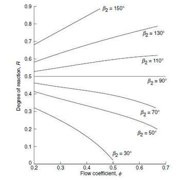
Degree of Reaction
The relative pressure or enthalpy drop in the nozzle and rotor blades are determined by the degree of reaction of the stage. This is defined by
R=

The two quantities within the parentheses in the numerator may have the same or opposite signs. This, besides other factors, would also govern the value of reaction. The stage reaction decreases as Cθ2 increases because this results in a large proportion of the stage enthalpy drop to occur in the nozzle ring.
Stage losses
The stage work is less than the isentropic stage enthalpy drop on account of aerodynamic losses in the stage. The actual output at the turbine shaft is equal to the stage work minus the losses due to rotor disc and bearing friction.
- (a) skin friction and separation losses in the scroll and nozzle ring
- They depend on the geometry and the coefficient of skin friction of these components.
- (b) Skin friction and separation losses in the rotor blade channels
- These losses are also governed by the channel geometry, coefficient of skin friction and the ratio of the relative velocities w3/w2. In the ninety degree IFR turbine stage, the losses occurring in the radial and axial sections of the rotor are sometimes separately considered.
- (c) Skin friction and separation losses in the diffuser
- These are mainly governed by the geometry of the diffuser and the rate of diffusion.
- (d) Secondary losses
- These are due to circulatory flows developing into the various flow passages and are principally governed by the aerodynamic loading of the blades. The main parameters governing these losses are b2/d2, d3/d2 and hub-tip ratio at the rotor exit.
- (e) Shock or incidence losses
- At off-design operation, there are additional losses in the nozzle and rotor blade rings on account of incidence at the leading edges of the blades. This loss is conventionally referred to as shock loss though it has nothing to do with the shock waves.
- (f) Tip clearance loss
- This is due to the flow over the rotor blade tips which does not contribute to the energy transfer.

Blade to Gas Speed Ratio
The blade-to-gas speed ratio can be expressed in terms of the isentropic stage terminal velocity c0.
![\,\sigma _{s}={\frac {u_{2}}{c_{0}}}=[2(1+\phi _{2}\cot {\beta _{2}}]^{{-1 \over {2}}}](../I/m/a505e38142cb0798e0ed19275e9d0a06ab8204d4.svg)
for β2=90o σs=0.707

Outward-flow radial stages
In outward flow radial turbine stages, the flow of the gas or steam occurs from smaller to larger diameters. The stage consists of a pair of fixed and moving blades. The increasing area of cross-section at larger diameters accommodates the expanding gas.
This configuration did not become popular with the steam and gas turbines. The only one which is employed more commonly is the Ljungstrom double rotation type turbine. It consists of rings of cantilever blades projecting from two discs rotating in opposite directions. The relative peripheral velocity of blades in two adjacent rows, with respect to each other, is high. This gives a higher value of enthalpy drop per stage.
Nikola Tesla's Bladeless Radial Turbine
In the early 1900s, Nikola Tesla developed and patented his Bladeless Turbine. One of the difficulties with bladed turbines is the complex and highly precise requirements for balancing and manufacturing the bladed rotor which has to be very well balanced. The blades are subject to corrosion and cavitation. Tesla attacked this problem by substituting a series of closely spaced disks for the blades of the rotor. The working fluid flows between the disks and transfers its energy to the rotor by means of the boundary layer effect or adhesion and viscosity rather than by impulse or reaction. Tesla stated his turbine could realize incredibly high efficiencies by steam. There has been no documented evidence yet of Tesla turbines achieving the efficiencies Tesla claimed.
In 2003 Scott O’Hearen took a patent on the Radial turbine blade system. This invention utilizes a combination of the concepts of a smooth runner surface for working fluid frictional contact and that of blades projecting axially from plural transverse runner faces. Author, Harikishan Gupta E., & Author, Shyam P. Kodali (2013). Design and Operation of Tesla Turbo machine - A state of the art review. International Journal of Advanced Transport Phenomena, 2(1), 2-3.
Notes
References
- 'Turbines, Compressors and Fans 4th Edition' [Author: S M Yahya; publisher: TATA McGraw-Hill Education (2010)] ISBN 9780070707023
- 'A review of cascade data on secondary losses in turbines' [Author: J Dunham ; J. Mech Eng Sci., 12, 1970]
- Osterle, J.F., ‘Thermodynamic considerations in the use of gasified coal as a fuel for power conversion systems’, Frontiers of power technology conference proceedings, Oklahoma State University, Carnegie-Mellon University, Pittsburgh, Oct. 1974.
- Starkey, N.E., ‘Long life base load service at 1600°F turbine inlet temperature’, ASME J. Eng. Power, Jan. 1967.
- Stasa, F.L. and Osterle, F., ‘The thermodynamic performance of two combined cycle power plants integrated with two coal gasification systems’, ASME J. Eng. Power, July 1981.
- Traenckner, K., ‘Pulverized-coal gasification Ruhrgas processes’, Trans ASME, 1953.
- Ushiyama, I., ‘Theoretically estimating the performance of gas turbines under varying atmospheric condition’, ASME J. Eng. Power, Jan. 1976.
- Yannone, R.A. and Reuther, J.F., ‘Ten years of digital computer control of combustion turbines ASME J. Engg. Power, 80-GT-76, Jan. 1981.
- Hubert, F.W.L. et al., Large combined cycles for utilities’, Combustion, Vol. I, ASME gas turbine conference and products show, Brussels, May 1970.
- Hurst, J.N. and Mottram, A.W.T., ‘Integrated Nuclear Gas turbines’, Paper No. EN-1/41, Symposium on the technology of integrated primary circuits for power reactors, ENEA, Paris, May 1968.
- Jackson, A.J.B., ‘Some future trends in aeroengine design for subsonic transport aircraft’,-ASME J. Eng. Power, April 1976.
- Kehlhofer, R., ‘Calculation for part-load operation of combined gas/steam turbine plants’, Brown Boveri Rev., 65, 10, pp 672–679, Oct. 1978.
- Kingcombe, R.C. and Dunning, S.W., ‘Design study for a fuel efficient turbofan engine’, ASME paper No. 80-GT-141, New Orleans, March 1980.
- Mayers, M.A. et al., ‘Combination gas turbine and steam turbine cycles’, ASME paper No. 55-A-184, 1955.
- Mcdonald, C.F. and Smith, M.J., ‘Turbomachinery design considerations for nuclear HTGR-GT power plant’, ASME J. Eng. Power, 80-GT-80, Jan. 1981.
- Mcdonald, C.F. and Boland, C.R., ‘The nuclear closed-cycle gas turbine (HTGR-GT) dry cooled commercial power plant studies’, ASME J. Eng. Power, 80-GT-82, Jan. 1981.
- Nabors, W.M. et al., ‘Bureau of mine progress in developing the coal burning gas turbine power plant’, ASME J. Eng. Power, April 1965.