Gasket
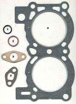
- 1. o-ring
- 2. fiber washer
- 3. paper gaskets
- 4. cylinder head gasket
A gasket is a mechanical seal which fills the space between two or more mating surfaces, generally to prevent leakage from or into the joined objects while under compression.
Gaskets allow for "less-than-perfect" mating surfaces on machine parts where they can fill irregularities. Gaskets are commonly produced by cutting from sheet materials.
Gaskets for specific applications, such as high pressure steam systems, may contain asbestos. However, due to health hazards associated with asbestos exposure, non-asbestos gasket materials are used when practical.[1]
It is usually desirable that the gasket be made from a material that is to some degree yielding such that it is able to deform and tightly fill the space it is designed for, including any slight irregularities. A few gaskets require an application of sealant directly to the gasket surface to function properly.
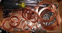
Some (piping) gaskets are made entirely of metal and rely on a seating surface to accomplish the seal; the metal's own spring characteristics are utilized (up to but not passing σy, the material's yield strength). This is typical of some "ring joints" (RTJ) or some other metal gasket systems. These joints are known as R-con and E-con compressive type joints.[2]
Properties
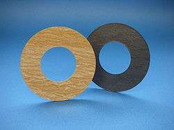
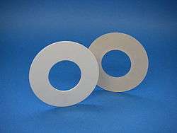
Gaskets are normally made from a flat material, a sheet such as paper, rubber, silicone, metal, cork, felt, neoprene, nitrile rubber, fiberglass, polytetrafluoroethylene (otherwise known as PTFE or Teflon) or a plastic polymer (such as polychlorotrifluoroethylene).
One of the more desirable properties of an effective gasket in industrial applications for compressed fiber gasket material is the ability to withstand high compressive loads. Most industrial gasket applications involve bolts exerting compression well into the 14 MPa (2000 psi) range or higher. Generally speaking, there are several truisms that allow for better gasket performance. One of the more tried and tested is: "The more compressive load exerted on the gasket, the longer it will last".
There are several ways to measure a gasket material's ability to withstand compressive loading. The "hot compression test" is probably the most accepted of these tests. Most manufacturers of gasket materials will provide or publish the results of these tests.
Gasket design
Gaskets come in many different designs based on industrial usage, budget, chemical contact and physical parameters:
Sheet gaskets
When a sheet of material has the gasket shape "punched out" of it, it is a sheet gasket. This can lead to a crude, fast and cheap gasket. In previous times the material was compressed asbestos, but in modern times a fibrous material such as graphite is used. These gaskets can fill various different chemical requirements based on the inertness of the material used. Non-asbestos gasket sheet is durable, of multiple materials, and thick in nature. Material examples are mineral, carbon or nitrile synthetic rubber. Applications using sheet gaskets involve acids, corrosive chemicals, steam or mild caustics. Flexibility and good recovery prevent breakage during installation of a sheet gasket.[3]
Solid material gaskets
The idea behind solid material is to use metals which cannot be punched out of sheets but are still cheap to produce. These gaskets generally have a much higher level of quality control than sheet gaskets and generally can withstand much higher temperatures and pressures. The key downside is that a solid metal must be greatly compressed in order to become flush with the flange head and prevent leakage. The material choice is more difficult; because metals are primarily used, process contamination and oxidation are risks. An additional downside is that the metal used must be softer than the flange — in order to ensure that the flange does not warp and thereby prevent sealing with future gaskets. Even so, these gaskets have found a niche in industry.
Spiral-wound gaskets
Spiral-wound gaskets comprise a mix of metallic and filler material.[4] Generally, the gasket has a metal (normally carbon rich or stainless steel) wound outwards in a circular spiral (other shapes are possible) with the filler material (generally a flexible graphite) wound in the same manner but starting from the opposing side. This results in alternating layers of filler and metal. The filler material in these gaskets acts as the sealing element, with the metal providing structural support.
These gaskets have proven to be reliable in most applications, and allow lower clamping forces than solid gaskets, albeit with a higher cost.
Constant seating stress gaskets
The constant seating stress gasket consists of two components; a solid carrier ring of a suitable material, such as stainless steel, and two sealing elements of some compressible material installed within two opposing channels, one channel on either side of the carrier ring. The sealing elements are typically made from a material (expanded graphite, expanded polytetrafluoroethylene (PTFE), vermiculite, etc.) suitable to the process fluid and application. Constant seating stress gaskets derive their name from the fact that the carrier ring profile takes flange rotation (deflection under bolt preload) into consideration. With all other conventional gaskets, as the flange fasteners are tightened, the flange deflects radially under load, resulting in the greatest gasket compression, and highest gasket stress, at the outer gasket edge.
Since the carrier ring used in constant seating stress gaskets take this deflection into account when creating the carrier ring for a given flange size, pressure class, and material, the carrier ring profile can be adjusted to enable the gasket seating stress to be radially uniform across the entire sealing area. Further, because the sealing elements are fully confined by the flange faces in opposing channels on the carrier ring, any in-service compressive forces acting on the gasket are transmitted through the carrier ring and avoid any further compression of the sealing elements, thus maintaining a 'constant' gasket seating stress while in-service. Thus, the gasket is immune to common gasket failure modes that include creep relaxation, high system vibration, or system thermal cycles. The fundamental concept underlying the improved sealability for constant seating stress gaskets are that (i) if the flange sealing surfaces are capable of attaining a seal, (ii) the sealing elements are compatible with the process fluid and application, and (iii) the sufficient gasket seating stress is achieved on installation necessary to affect a seal, then the possibility of the gasket leaking in-service is greatly reduced or eliminated altogether.
Double-jacketed gaskets
Double-jacketed gaskets are another combination of filler material and metallic materials. In this application, a tube with ends that resemble a "C" is made of the metal with an additional piece made to fit inside of the "C" making the tube thickest at the meeting points. The filler is pumped between the shell and piece. When in use, the compressed gasket has a larger amount of metal at the two tips where contact is made (due to the shell/piece interaction) and these two places bear the burden of sealing the process. Since all that is needed is a shell and piece, these gaskets can be made from almost any material that can be made into a sheet and a filler can then be inserted.[5]
Kammprofile gaskets
Kammprofile gaskets are used in many older seals since they have both a flexible nature and reliable performance. Kammprofiles work by having a solid corrugated core with a flexible covering layer. This arrangement allows for very high compression and an extremely tight seal along the ridges of the gasket. Since generally the graphite will fail instead of the metal core, Kammprofile can be repaired during later inactivity. Kammprofile has a high capital cost for most applications but this is countered by long life and increased reliability.
Flange gasket
A flange gasket is a type of gasket made to fit between two sections of pipe that are flared to provide higher surface area.
Flange gaskets come in a variety of sizes and are categorized by their inside diameter and their outside diameter.
There are many standards in gasket for flanges of pipes. The gaskets for flanges can be divided in major 4 different categories:
- Sheet gaskets
- Corrugated metal gaskets
- Ring gaskets
- spiral wound gaskets
Sheet gaskets are simple, they are cut to size either with bolt holes or without holes for standard sizes with various thickness and material suitable to media and temperature pressure of pipeline.
Ring gaskets also known as RTJ. They are mostly used in offshore oil- and gas pipelines and are designed to work under extremely high pressure. They are solid rings of metal in different cross sections like oval, round, octagonal etc. Sometimes they come with hole in center for pressure .
Spiral wound gaskets are also used in high pressure pipelines and are made with stainless steel outer and inner rings and a center filled with spirally wound stainless steel tape wound together with graphite and PTFE, formed in V shape. Internal pressure acts upon the faces of the V, forcing the gasket to seal against the flange faces.
Improvements
Many gaskets contain minor improvements to increase or infer acceptable operating conditions:
- A common improvement is an inner compression ring. A compression ring allows for higher flange compression while preventing gasket failure. The effects of a compression ring are minimal and generally are just used when the standard design experiences a high rate of failure.
- A common improvement is an outer guiding ring. A guiding ring allows for easier installation and serves as a minor compression inhibitor. In some alkylation uses these can be modified on Double Jacketed gaskets to show when the first seal has failed through an inner lining system coupled with alkylation paint.
Reasons for failure
Uneven distributed pressing force
Uneven pressing force is caused by a variety of factors, first is the human factor: asymmetric construction of the preload bolt, this factor can eliminate construction; theory on the flange pressed, the sealing surface is absolutely parallel to the practice, however, the centerline of a pipeline can not be absolutely concentric, and thus tighten the bolts on the flange moment, so that the flange discontinuity. Asymmetrical connection, the sealing surface more or less deformed, so that sealed the pressing force is reduced, the running load, prone to leakage. Third, the density of bolt arrangement on the pressure distribution more obvious impact, the closer the bolts, the more uniform the pressure.
Stress relaxation and torque loss
Tighten bolts on the flange, due to the vibration of the bodies, the temperature increased or decreased and other factors, the working process of the spiral wound gaskets stress relaxation, the bolt tension will be gradually decreased, resulting in loss of torque, causing a leak. In general, long bolts, the remnants of the torque, the smaller the diameter the more advantageous to prevent the loss of torque, with long, thin bolt is an effective way to prevent torque loss. Heating a certain period of time to make it stretch the bolt, and then to maintain a given torque, is very effective to prevent the loss of torque. There is a gasket is thinner and smaller the loss of torque. In addition to prevent the strong vibration of the machine and the pipe itself, and exclude the impact of adjacent equipment vibration, the impact of the sealing surface is not meaningless, not to beat the bolts tightened, can prevent the loss of torque.
Surface not smooth
It is important to make the sealing finish properly otherwise it will cause leakage.
See also
Sources
| Wikimedia Commons has media related to Gaskets. |
- ↑ "Gaskets and Gasketed Joints", John Bickford, Retrieved April 21, 2016
- ↑
- ↑ "Material Spotlight Series: Compressed Sheet", GRI, Retrieved April 21, 2016
- ↑ "Spiral Wound Gaskets", GRI, Retrieved April 21, 2016
- ↑ "[asmedigitalcollection.asme.org Revisiting Gasket Selection: A Flowchart Approach -- Updates for the 25th Anniversary]", Anita Bausman and A. Fitzgerald Waterland, Retrieved April 21, 2016
- Bickford, John H.: An Introduction to the Design and Behavior of Bolted Joints, 3rd ed., Marcel Dekker, 1995, pg. 5
- Latte, Dr. Jorge and Rossi, Claudio: High Temperature Behavior of Compressed Fiber Gasket Materials, and an Alternative Approach to the Prediction of Gasket Life, FSA presented Paper, 1995, pg. 16
{{Navbox |name =Automotive engine |state =collapsed |title =Automotive engine |listclass =hlist
|above =Part of the Automobile series
|group1 =Basic terminology |list1 =
- Compression ratio
- Crank
- Cylinder
- Dead centre
- Diesel engine
- Dry sump
- Engine balance
- Engine configuration
- Engine displacement
- Engine knocking
- Firing order
- Hydrolock
- Petrol engine
- Power band
- Redline
- Spark-ignition engine
- Stroke
- Stroke ratio
- Wet sump
|group2 =Main components |list2 =
- Connecting rod
- Crankcase
- Crankpin
- Crankshaft
- Crossflow cylinder head
- Crossplane
- Cylinder bank
- [[]
- Starter ring gear
- Sump
|group3 =Valvetrain |list3 =
- Cam
- Cam follower
- Camshaft
- Desmodromic valve
- Hydraulic tappet
- Multi-valve
- Overhead camshaft
- Overhead valve
- Pneumatic valve springs
- Poppet valve
- Pushrod
- Rocker arm
- Sleeve valve
- Tappet
- Timing belt
- Timing mark
- Valve float
- Variable valve timing
|group4 =Aspiration |list4 =
- Air filter
- Blowoff valve
- Boost controller
- Butterfly valve
- Centrifugal-type supercharger
- Cold air intake
- Dump valve
- Electronic throttle control
- Forced induction
- Inlet manifold
- Intake
- Intercooler
- Manifold vacuum
- Naturally aspirated engine
- Ram-air intake
- Scroll-type supercharger
- Short ram air intake
- Supercharger
- Throttle
- Throttle body
- Turbocharger
- Twin-turbo
- Variable-geometry turbocharger
- Variable-length intake manifold
- Warm air intake
|group5 =Fuel system |list5 =
- Carburetor
- Common rail
- Direct injection
- Fuel filter
- Fuel injection
- Fuel pump
- Fuel tank
- Gasoline direct injection
- Indirect injection
- Injection pump
- Lean-burn
- Stratified charge engine
- Turbo fuel stratified injection
- Unit injector
|group6 =Ignition |list6 =
- Contact breaker
- Magneto
- Distributor
- Electrical ballast
- High tension leads
- Ignition coil
- Spark plug
- Wasted spark
|group7 =
management
|list7 =
- Air–fuel ratio meter
- Alternator
- Automatic Performance Control
- Car battery (lead–acid battery)
- Crankshaft position sensor
- Dynamo
- Drive by wire
- Electronic control unit
- Engine control unit
- Engine coolant temperature sensor
- Glow plug
- Idle air control actuator
- MAP sensor
- Mass flow sensor
- Oxygen sensor
- Starter motor
- Throttle position sensor
|group8 =Exhaust system |list8 =
- Automobile emissions control
- Catalytic converter
- Diesel particulate filter
- Exhaust manifold
- Glasspack
- Muffler
|group9 =Engine cooling |list9 =
- Air cooling
- Antifreeze (ethylene glycol)
- Core plug
- Electric fan
- Fan belt
- Radiator
- Thermostat
- Water cooling
- Viscous fan (fan clutch)
|group10 =Other components |list10 =
- Balance shaft
- Block heater
- Combustion chamber
- Cylinder head porting
- Gasket
- Motor oil
- Oil filter
- Oil pump
- Oil sludge
- PCV valve
- Seal
- Synthetic oil
- Underdrive pulleys
|belowclass =hlist |belowstyle =font-weight:bold; |below =
- Portal
- Category
}}