Inlet manifold
In automotive engineering, an inlet manifold or intake manifold (in American English) is the part of an engine that supplies the fuel/air mixture to the cylinders. The word manifold comes from the Old English word manigfeald (from the Anglo-Saxon manig [many] and feald [repeatedly]) and refers to the multiplying of one (pipe) into many.[1]
In contrast, an exhaust manifold collects the exhaust gases from multiple cylinders into a smaller number of pipes – often down to one pipe.
The primary function of the intake manifold is to evenly distribute the combustion mixture (or just air in a direct injection engine) to each intake port in the cylinder head(s). Even distribution is important to optimize the efficiency and performance of the engine. It may also serve as a mount for the carburetor, throttle body, fuel injectors and other components of the engine.
Due to the downward movement of the pistons and the restriction caused by the throttle valve, in a reciprocating spark ignition piston engine, a partial vacuum (lower than atmospheric pressure) exists in the intake manifold. This manifold vacuum can be substantial, and can be used as a source of automobile ancillary power to drive auxiliary systems: power assisted brakes, emission control devices, cruise control, ignition advance, windshield wipers, power windows, ventilation system valves, etc.
This vacuum can also be used to draw any piston blow-by gases from the engine's crankcase. This is known as a positive crankcase ventilation system, in which the gases are burned with the fuel/air mixture.
The intake manifold has historically been manufactured from aluminum or cast iron, but use of composite plastic materials is gaining popularity (e.g. most Chrysler 4-cylinders, Ford Zetec 2.0, Duratec 2.0 and 2.3, and GM's Ecotec series).
Turbulence
The carburetor or the fuel injectors spray fuel droplets into the air in the manifold. Due to electrostatic forces some of the fuel will form into pools along the walls of the manifold, or may converge into larger droplets in the air. Both actions are undesirable because they create inconsistencies in the air-fuel ratio. Turbulence in the intake causes forces of uneven proportions in varying vectors to be applied to the fuel, aiding in atomization. Better atomization allows for a more complete burn of all the fuel and helps reduce engine knock by enlarging the flame front. To achieve this turbulence it is a common practice to leave the surfaces of the intake and intake ports in the cylinder head rough and unpolished.
Only a certain degree of turbulence is useful in the intake. Once the fuel is sufficiently atomized additional turbulence causes unneeded pressure drops and a drop in engine performance.
Volumetric efficiency

The design and orientation of the intake manifold is a major factor in the volumetric efficiency of an engine. Abrupt contour changes provoke pressure drops, resulting in less air (and/or fuel) entering the combustion chamber; high-performance manifolds have smooth contours and gradual transitions between adjacent segments.
Modern intake manifolds usually employ runners, individual tubes extending to each intake port on the cylinder head which emanate from a central volume or "plenum" beneath the carburetor. The purpose of the runner is to take advantage of the Helmholtz resonance property of air. Air flows at considerable speed through the open valve. When the valve closes, the air that has not yet entered the valve still has a lot of momentum and compresses against the valve, creating a pocket of high pressure. This high-pressure air begins to equalize with lower-pressure air in the manifold. Due to the air's inertia, the equalization will tend to oscillate: At first the air in the runner will be at a lower pressure than the manifold. The air in the manifold then tries to equalize back into the runner, and the oscillation repeats. This process occurs at the speed of sound, and in most manifolds travels up and down the runner many times before the valve opens again.
The smaller the cross-sectional area of the runner, the higher the pressure changes on resonance for a given airflow. This aspect of Helmholtz resonance reproduces one result of the Venturi effect. When the piston accelerates downwards, the pressure at the output of the intake runner is reduced. This low pressure pulse runs to the input end, where it is converted into an over-pressure pulse. This pulse travels back through the runner and rams air through the valve. The valve then closes.
To harness the full power of the Helmholtz resonance effect, the opening of the intake valve must be timed correctly, otherwise the pulse could have a negative effect. This poses a very difficult problem for engines, since valve timing is dynamic and based on engine speed, whereas the pulse timing is static and dependent on the length of the intake runner and the speed of sound. The traditional solution has been to tune the length of the intake runner for a specific engine speed where maximum performance is desired. However, modern technology has given rise to a number of solutions involving electronically controlled valve timing (for example Valvetronic), and dynamic intake geometry (see below).
As a result of "resonance tuning", some naturally aspirated intake systems operate at a volumetric efficiency above 100%: the air pressure in the combustion chamber before the compression stroke is greater than the atmospheric pressure. In combination with this intake manifold design feature, the exhaust manifold design, as well as the exhaust valve opening time can be so calibrated as to achieve greater evacuation of the cylinder. The exhaust manifolds achieve a vacuum in the cylinder just before the piston reaches top dead center. The opening inlet valve can then—at typical compression ratios—fill 10% of the cylinder before beginning downward travel. Instead of achieving higher pressure in the cylinder, the inlet valve can stay open after the piston reaches bottom dead center while the air still flows in.
In some engines the intake runners are straight for minimal resistance. In most engines, however, the runners have curves...and some very convoluted to achieve desired runner length. These turns allow for a more compact manifold, with denser packaging of the whole engine, as a result. Also, these "snaked" runners are needed for some variable length/ split runner designs, and allow the size of the plenum to be reduced. In an engine with at least six cylinders the averaged intake flow is nearly constant and the plenum volume can be smaller. To avoid standing waves within the plenum it is made as compact as possible. The intake runners each use a smaller part of the plenum surface than the inlet, which supplies air to the plenum, for aerodynamic reasons. Each runner is placed to have nearly the same distance to the main inlet. Runners whose cylinders fire close after each other, are not placed as neighbors.
"180-degree intake manifolds"....Originally designed for carburetor V8 engines, the two plane, split plenum intake manifold separates the intake pulses which the manifold experiences by 180 degrees in the firing order. This minimizes interference of one cylinder's pressure waves with those of another, giving better torque from smooth mid-range flow. Such manifolds may have been originally designed for either two- or four-barrel carburetors, but now are used with both throttle-body and multi-point fuel injection. An example of the latter is the Honda J engine which converts to a single plane manifold around 3500 rpm for greater peak flow and horsepower.
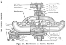
"Heat Riser"....now obsolete, earlier manifolds ...with 'wet runners' for carbureted engines...used exhaust gas diversion through the intake manifold to provide vaporizing heat. The amount of exhaust gas flow diversion was controlled by a heat riser valve in the exhaust manifold, and employed a bi-metallic spring which changed tension according to the heat in the manifold. Today's fuel-injected engines do not require such devices.
Variable-length intake manifold

Variable-Length Intake Manifold (VLIM) is an internal combustion engine manifold technology. Four common implementations exist. First, two discrete intake runners with different length are employed, and a butterfly valve can close the short path. Second the intake runners can be bent around a common plenum, and a sliding valve separates them from the plenum with a variable length. Straight high-speed runners can receive plugs, which contain small long runner extensions. The plenum of a 6- or 8-cylinder engine can be parted into halves, with the even firing cylinders in one half and the odd firing cylinders in the other part. Both sub-plenums and the air intake are connected to an Y (sort of main plenum). The air oscillates between both sub-plenums, with a large pressure oscillation there, but a constant pressure at the main plenum. Each runner from a sub plenum to the main plenum can be changed in length. For V engines this can be implemented by parting a single large plenum at high engine speed by means of sliding valves into it when speed is reduced.
As the name implies, VLIM can vary the length of the intake tract in order to optimize power and torque, as well as provide better fuel efficiency.
There are two main effects of variable intake geometry:
- Venturi effect - At low rpm, the speed of the airflow is increased by directing the air through a path with limited capacity (cross-sectional area). The larger path opens when the load increases so that a greater amount of air can enter the chamber. In dual overhead cam (DOHC) designs, the air paths are often connected to separate intake valves so the shorter path can be excluded by deactivating the intake valve itself.
- Pressurization - A tuned intake path can have a light pressurizing effect similar to a low-pressure supercharger due to Helmholtz resonance. However, this effect occurs only over a narrow engine speed range which is directly influenced by intake length. A variable intake can create two or more pressurized "hot spots." When the intake air speed is higher, the dynamic pressure pushing the air (and/or mixture) inside the engine is increased. The dynamic pressure is proportional to the square of the inlet air speed, so by making the passage narrower or longer the speed/dynamic pressure is increased.
Many automobile manufacturers use similar technology with different names. Another common term for this technology is Variable Resonance Induction System (VRIS).
- Audi - 2.8-liter V6 gas engine (1991–98); 3.6- and 4.2-liter V8 engines, 1987–present
- Alfa Romeo - 2.0 TwinSpark 16v - 155 ps(114 kW)
- BMW DISA and DIVA systems
- Dodge - 2.0 A588 - ECH (2001–2005) used in the 2001–2005 model year Dodge Neon R/T
- Ferrari - 360 Modena, 550 Maranello
- Ford VIS (Variable-resonance Intake System) - on their 2.9-liter 24V Cosworth (BOB) based on the Ford Cologne V6 engine in the later model Ford Scorpio.
- Ford DSI (Dual-Stage Intake) - on their Duratec 2.5- and 3.0-liter V6s and it was also found on the Yamaha V6 in the Taurus SHO.
- Ford - The Ford Modular V8 engines sport either the Intake Manifold Runner Control (IMRC) for 4V engines, or the Charge Motion Control Valve (CMCV) for 3V engines.
- Ford - The 2.0L Split Port engine in the Ford Escort and Mercury Tracer feature an Intake Manifold Runner Control variable geometry intake manifold.
- General Motors - 3.9L LZ8/LZ9 V6, 3.2L LA3 V6, and the 4.3L LF4 V6 in some second generation S10s and Sonomas
- GM Daewoo - DOHC versions of E-TEC II engines
- Holden - Alloytec
- Honda - Integra, Legend, NSX, Prelude
- Hyundai - XG V6
- Isuzu - Isuzu Rodeo Used in the second generation V6, 3.2L (6VD1) Rodeos.
- Jaguar - AJ-V6
- Lancia VIS
- Mazda VICS (Variable Inertia Charging System) is used on the Mazda FE-DOHC engine and Mazda B engine family of straight-4s, and VRIS (Variable Resistance Induction System) in the Mazda K engine family of V6 engines. An updated version of this technology is employed on the new Mazda Z engine, which is also used by Ford as the Duratec.
- Mercedes-Benz
- MG - MG ZS 180 MG ZT 160, 180 and 190
- Mitsubishi Cyclone is used on the 2.0L I4 4G63 engine family.
- Nissan I4, V6, V8
- Opel (or Vauxhall) TwinPort - modern versions of Ecotec Family 1 and Ecotec Family 0 straight-4 engines; a similar technology is used in 3.2 L 54° V6 engine
- Peugeot 2.2 L I4, 3.0 L V6
- Porsche VarioRam - 964, 993, 996, Boxster
- Proton Campro CPS and VIM - Proton Gen-2 CPS and Proton Waja CPS; Proton Campro IAFM - 2008 Proton Saga 1.3
- Renault - Clio 2.0RS
- Rover - Rover 623 Rover 825 Rover 75 v6 Rover 45 v6
- Subaru Legacy 1989–1994 JDM EJ20 2.0-liter naturally aspirated DOHC 16-valve flat-4
- Subaru SVX 1992–1997 EG33 3.3-liter naturally aspirated DOHC 24-valve flat-6
- Subaru Legacy and Subaru Impreza1999–2001 JDM EJ20 2.0-liter naturally aspirated DOHC 16-valve flat-4
- Toyota T-VIS - (Toyota Variable Induction System) used in the early versions of the 3S-GE, 7M-GE, and 4A-GE engines, and ACIS - (Acoustic Control Induction System).
- Volkswagen - 1.6 L I4, VR6, W8
- Volvo - VVIS (Volvo Variable Induction System) Volvo B52 engine as found on the Volvo 850 and S70/V70 vehicles, and their successors. Longer inlet ducts used between 1500 and 4100 rpm at 80% load or higher.[2]
See also
References
| Wikimedia Commons has media related to Intake manifolds. |
- ↑ manifold, (adv.) "in the proportion of many to one, by many times". AD1526 Oxford English Dictionary,
- ↑ Volvoclub UK: 850GLT Engine Info