Lead–acid battery
|
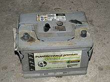
Lead–acid car battery | |
| Specific energy | 33[1]–42 Wh/kg[2] |
|---|---|
| Energy density | 60–110 Wh/L[2] |
| Specific power | 180 W/kg[3] |
| Charge/discharge efficiency | 50–95%[4] |
| Energy/consumer-price | 7 (sld) to 18 (fld) Wh/US$[5] |
| Self-discharge rate | 3–20%/month[2] |
| Cycle durability | 500–800 cycles[6] |
| Nominal cell voltage | 2.0 V[7] |
| Charge temperature interval | Min. −35 °C, max. 45 °C |

The lead-acid battery was invented in 1859 by French physicist Gaston Planté and is the oldest type of rechargeable battery. Despite having a very low energy-to-weight ratio and a low energy-to-volume ratio, its ability to supply high surge currents means that the cells have a relatively large power-to-weight ratio. These features, along with their low cost, makes it attractive for use in motor vehicles to provide the high current required by automobile starter motors.
As they are inexpensive compared to newer technologies, lead-acid batteries are widely used even when surge current is not important and other designs could provide higher energy densities. Large-format lead-acid designs are widely used for storage in backup power supplies in cell phone towers, high-availability settings like hospitals, and stand-alone power systems. For these roles, modified versions of the standard cell may be used to improve storage times and reduce maintenance requirements. Gel-cells and absorbed glass-mat batteries are common in these roles, collectively known as VRLA (valve-regulated lead-acid) batteries.
Lead–acid battery sales account for 40–45% of the value from batteries sold worldwide (1999, not including China and Russia), a manufacturing market value of about $15 billion.[8]
History
The French scientist Gautherot observed in 1801 that wires that had been used for electrolysis experiments would themselves provide a small amount of "secondary" current after the main battery had been disconnected.[9] In 1859, Gaston Planté's lead–acid battery was the first battery that could be recharged by passing a reverse current through it. Planté's first model consisted of two lead sheets separated by rubber strips and rolled into a spiral.[10] His batteries were first used to power the lights in train carriages while stopped at a station. In 1881, Camille Alphonse Faure invented an improved version that consisted of a lead grid lattice, into which a lead oxide paste was pressed, forming a plate. This design was easier to mass-produce. An early manufacturer (from 1886) of lead–acid batteries was Henri Tudor.
Using a gel electrolyte instead of a liquid allows the battery to be used in different positions without leakage. Gel electrolyte batteries for any position date from 1930s, and even in the late 1920s portable suitcase radio sets allowed the cell vertical or horizontal (but not inverted) due to valve design (see third Edition of Wireless Constructor's Encyclopaedia by Frederick James Camm). In the 1970s, the valve-regulated lead acid battery (often called "sealed") was developed, including modern absorbed glass mat types, allowing operation in any position.
Electrochemistry
Discharge
In the discharged state both the positive and negative plates become lead(II) sulfate (PbSO
4), and the electrolyte loses much of its dissolved sulfuric acid and becomes primarily water.
The discharge process is driven by the conduction of electrons from the negative plate back into the cell at the positive plate in the external circuit.
- Negative plate reaction
- Pb(s) + HSO−
4(aq) → PbSO
4(s) + H+
(aq) + 2e− Release of two conducting electrons gives lead electrode a net negative charge
• As electrons accumulate they create an electric field which attracts hydrogen ions and repels sulfate ions, leading to a double-layer near the surface. The hydrogen ions screen the charged electrode from the solution which limits further reactions unless charge is allowed to flow out of electrode.
- Positive plate reaction
- PbO
2(s) + HSO−
4(aq) + 3H+
(aq) + 2e− → PbSO
4(s) + 2H
2O(l)
The total reaction can be written as
- Pb(s) + PbO
2(s) + 2H
2SO
4(aq) → 2PbSO
4(s) + 2H
2O(l)
The sum of the molecular masses of the reactants is 642.6 g/mol, so theoretically a cell can produce two faradays of charge (192,971 coulombs) from 642.6 g of reactants, or 83.4 ampere-hours per kilogram (or 13.9 ampere-hours per kilogram for a 12-volt battery). For a 2 volts cell, this comes to 167 watt-hours per kilogram of reactants, but a lead–acid cell in practice gives only 30–40 watt-hours per kilogram of battery, due to the mass of the water and other constituent parts.
Charging
In the fully charged state, the negative plate consists of lead, and the positive plate lead dioxide, with the electrolyte of concentrated sulfuric acid.
Overcharging with high charging voltages generates oxygen and hydrogen gas by electrolysis of water, which is lost to the cell. The design of some types of lead-acid battery allow the electrolyte level to be inspected and topped up with any water that has been lost.
Due to the freezing-point depression of the electrolyte, as the battery discharges and the concentration of sulfuric acid decreases, the electrolyte is more likely to freeze during winter weather when discharged.
Ion motion
During discharge, H+
produced at the negative plates moves into the electrolyte solution and then is consumed into the positive plates, while HSO−
4 is consumed at both plates. The reverse occurs during charge. This motion can be by electrically driven proton flow or Grotthuss mechanism, or by diffusion through the medium, or by flow of a liquid electrolyte medium. Since the density is greater when the sulfuric acid concentration is higher, the liquid will tend to circulate by convection. Therefore, a liquid-medium cell tends to rapidly discharge and rapidly charge more efficiently than an otherwise similar gel cell.
Measuring the charge level
.png)
Because the electrolyte takes part in the charge-discharge reaction, this battery has one major advantage over other chemistries. It is relatively simple to determine the state of charge by merely measuring the specific gravity of the electrolyte; the specific gravity falls as the battery discharges. Some battery designs include a simple hydrometer using colored floating balls of differing density. When used in diesel-electric submarines, the specific gravity was regularly measured and written on a blackboard in the control room to indicate how much longer the boat could remain submerged.[11]
The battery's open-circuit voltage can also be used to gauge the state of charge.[12] If the connections to the individual cells are accessible, then the state of charge of each cell can be determined which can provide a guide as to the state of health of the battery as a whole, otherwise the overall battery voltage may be assessed.
Note that neither technique gives any indication of charge capacity, only charge level. Charge capacity of any rechargeable battery will decline with age and usage, meaning that it may no longer be fit for purpose even when nominally fully charged. Other tests, usually involving current drain, are used to determine the residual charge capacity of a battery.
Voltages for common usages
For the three-stage charging procedure of lead acid batteries, see IUoU battery charging. The theoretical voltage of a lead acid battery is 12 V for 6 cages and 2 V for one cage. These are general voltage ranges per cell:
- Open-circuit (quiescent) at full charge: 2.10 V
- Open-circuit at full discharge: 1.95 V
- Loaded at full discharge: 1.8 V
- Continuous-preservation (float) charging: 2.23 V for gelled electrolyte; 2.25 V for absorbed glass mat (AGM) and 2.32 V for flooded cells. Float voltage recommendations vary among manufacturers due to different lead acid concentration and positive plate grid alloy. Precise float voltage (±0.05 V) is critical to longevity; insufficient voltage (causes sulfation) is almost as detrimental as excessive voltage (causes positive plate corrosion, expansion and electrolyte loss.)
- Typical (daily) charging: 2.28–2.4 V (depending on temperature and manufacturer's recommendation)
- Equalization charging (for flooded lead acids): 2.5–2.67 V[13] (5 A per 100 Ah,[14] Battery temperature must be absolutely monitored very closely, check manufacturers recommendation)
- Charging in sulfated state (stored discharged for days or weeks) not accepting small charge current: > 3 V[15] (only until a charge current is flowing)
- Charging in sulfated state: up to 2.6–2.66 V[16]
- Discharging in sulfated state: 1.6 V (when charging at low rates doesn't improve, discharge rate approximately 5 A per 10 Ah)[16]
- Gassing threshold: 2.415 V[17]–2.48[18] for sealed, 2.41 V for PzS, 2.36–2.41 V for GiS, PzV, GiV[19] (the value is manufacturer specific, gas is always produced even in storage,[20] 99% of the gas production recombines under normal charging conditions, the higher the voltage exponentially more gas is produced: from 2.3 to 2.5 is factor 1 to > 20,[21] charging above the gassing voltage with high charging current the side reaction will occur enhanced[19])
All voltages are at 20 °C (68 °F), and must be adjusted for temperature changes. The open-circuit voltage cannot be adjusted with a simple temperature coefficient because it is non-linear (coefficient varies with temperature). See voltage vs. temperature table.
Construction
Plates
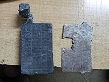
The lead–acid cell can be demonstrated using sheet lead plates for the two electrodes. However, such a construction produces only around one ampere for roughly postcard-sized plates, and for only a few minutes.
Gaston Planté found a way to provide a much larger effective surface area. In Planté's design, the positive and negative plates were formed of two spirals of lead foil, separated with a sheet of cloth and coiled up. The cells initially had low capacity, so a slow process of "forming" was required to corrode the lead foils, creating lead dioxide on the plates and roughening them to increase surface area. Initially this process used electricity from primary batteries; when generators became available after 1870, the cost of production of batteries greatly declined.[8] Planté plates are still used in some stationary applications, where the plates are mechanically grooved to increase their surface area.
In 1880, Camille Alphonse Faure patented a method of coating a lead grid (which serves as the current conductor) with a paste of lead oxides, sulfuric acid and water, followed by curing phase in which the plates were exposed to gentle heat in a high humidity environment. The curing process caused the paste to change to a mixture of lead sulfates which adhered to the lead plate. Then, during the battery's initial charge (called "formation") the cured paste on the plates was converted into electrochemically active material (the "active mass"). Faure's process significantly reduced the time and cost to manufacture lead–acid batteries, and gave a substantial increase in capacity compared with Planté's battery.[22] Faure's method is still in use today, with only incremental improvements to paste composition, curing (which is still done with steam, but is now a very tightly controlled process), and structure and composition of the grid to which the paste is applied.
The grid developed by Faure was of pure lead with connecting rods of lead at right angles. In contrast, present-day grids are structured for improved mechanical strength and improved current flow. In addition to different grid patterns (ideally, all points on the plate are equidistant from the power conductor), modern-day processes also apply one or two thin fibre-glass mats over the grid to distribute the weight more evenly. And while Faure had used pure lead for his grids, within a year (1881) these had been superseded by lead-antimony (8–12%) alloys to give the structures additional rigidity. However, high-antimony grids have higher hydrogen evolution (which also accelerates as the battery ages), and thus greater outgassing and higher maintenance costs. These issues were identified by U. B. Thomas and W. E. Haring at Bell Labs in the 1930s and eventually led to the development of lead-calcium grid alloys in 1935 for standby power batteries on the U.S. telephone network. Related research led to the development of lead-selenium grid alloys in Europe a few years later. Both lead-calcium and lead-selenium grid alloys still add antimony, albeit in much smaller quantities than the older high-antimony grids: lead-calcium grids have 4–6% antimony while lead-selenium grids have 1–2%. These metallurgical improvements give the grid more strength, which allows it carry more weight, i.e. more active material, and so the plates can be thicker, which in turn contributes to battery lifespan since there is more material available to shed before the battery becomes unusable. High-antimony alloy grids are still used in batteries intended for frequent cycling, e.g. in motor-starting applications where frequent expansion/contraction of the plates needs to be compensated for, but where outgassing is not significant since charge currents remain low. Since the 1950s, batteries designed for infrequent cycling applications (e.g., standby power batteries) increasingly have lead-calcium or lead-selenium alloy grids since these have less hydrogen evolution and thus lower maintenance overhead. Lead-calcium alloy grids are cheaper to manufacture (the cells thus have lower up-front costs), and have a lower self-discharge rate, and lower watering requirements, but have slightly poorer conductivity, are mechanically weaker (and thus require more antimony to compensate), and are strongly subject to corrosion (and thus a shorter lifespan) than cells with lead-selenium alloy grids.
Allegedly the US Navy submarines have switched from trickle charging AGM (lead calcium plate technology) to cycling the battery between trickle discharging, and trickle charging their batteries to prevent the open circuit effect caused by the calcium in the lead grids. This open circuit effect is caused by the calcium oxidizing.
The open circuit effect is also known as the antimony free effect.[23][24]
Modern-day paste contains carbon black, blanc fixe (barium sulfate) and lignosulfonate. The blanc fixe acts as a seed crystal for the lead–to–lead sulfate reaction. The blanc fixe must be fully dispersed in the paste in order for it to be effective. The lignosulfonate prevents the negative plate from forming a solid mass during the discharge cycle, instead enabling the formation of long needle–like dendrites. The long crystals have more surface area and are easily converted back to the original state on charging. Carbon black counteracts the effect of inhibiting formation caused by the lignosulfonates. Sulfonated naphthalene condensate dispersant is a more effective expander than lignosulfonate and speeds up formation. This dispersant improves dispersion of barium sulfate in the paste, reduces hydroset time, produces a more breakage-resistant plate, reduces fine lead particles and thereby improves handling and pasting characteristics. It extends battery life by increasing end-of-charge voltage. Sulfonated naphthalene requires about one-third to one-half the amount of lignosulfonate and is stable to higher temperatures.[25]
Once dry, the plates are stacked with suitable separators and inserted in a cell container. The alternate plates then constitute alternating positive and negative electrodes, and within the cell are later connected to one another (negative to negative, positive to positive) in parallel. The separators inhibit the plates from touching each other, which would otherwise constitute a short circuit. In flooded and gel cells, the separators are insulating rails or studs, formerly of glass or ceramic, and now of plastic. In AGM cells, the separator is the glass mat itself, and the rack of plates with separators are squeezed together before insertion into the cell; once in the cell, the glass mats expand slightly, effectively locking the plates in place. In multi-cell batteries, the cells are then connected to one another in series, either through connector through the cell walls, or by a bridge over the cell walls. All intra-cell and inter-cell connections are of the same lead alloy as that used in the grids. This is necessary to prevent galvanic corrosion.
So-called "deep cycle" batteries employ a different geometry for their positive electrodes. In this geometry, the positive electrode is not a flat plate but a row of lead-oxide cylinders or tubes strung side by side (hence the term "tubular" or "cylindrical" batteries for this geometry). The advantage of this geometry is an increased surface area in contact with the electrolyte, which in turn allows higher discharge/charge currents than a flat-plate cell of the same volume and depth-of-charge. Tubular-electrode cells thus exhibit a higher power density than flat-plate cells. This makes tubular/cylindrical geometry plates especially suitable for high-current applications with storage weight/space limitations, such as for forklifts or for starting marine diesel engines. However, because tubes/cylinders have less active material in the same volume, they also have a lower energy density than flat-plate cells. And, less active material at the electrode also means they have less material available to shed before the cell becomes unusable. Tubular/cylindrical electrodes are also more complicated to manufacture uniformly, which tends to make them more expensive than flat-plate cells. These trade-offs limit the range of applications in which tubular/cylindrical batteries are meaningful to situations where there is insufficient space to install higher capacity (and thus larger) flat-plate units.
About 60% of the weight of an automotive-type lead–acid battery rated around 60 A·h (8.7 kg of a 14.5 kg battery) is lead or internal parts made of lead; the balance is electrolyte, separators, and the case.[8]
Separators
Separators between the positive and negative plates prevent short-circuit through physical contact, mostly through dendrites ("treeing"), but also through shedding of the active material. Separators obstruct the flow of ions between the plates and increase the internal resistance of the cell. Wood, rubber, glass fiber mat, cellulose, and PVC or polyethylene plastic have been used to make separators. Wood was the original choice, but deteriorated in the acid electrolyte. Rubber separators are stable in battery acid and provide valuable electrochemical advantages that other materials cannot.
An effective separator must possess a number of mechanical properties; such as permeability, porosity, pore size distribution, specific surface area, mechanical design and strength, electrical resistance, ionic conductivity, and chemical compatibility with the electrolyte. In service, the separator must have good resistance to acid and oxidation. The area of the separator must be a little larger than the area of the plates to prevent material shorting between the plates. The separators must remain stable over the battery's operating temperature range.
Absorbed glass mat (AGM)
In the absorbed glass mat design, or AGM for short, the spaces between the cells is replaced by a glass fibre mat soaked in electrolyte. There is only enough electrolyte in the mat to keep it wet, and if the battery is punctured the electrolyte will not flow out of the mats. Likewise, the mat greatly reduces evaporation, to the point that the batteries do not require periodic refilling of the water. This combination of features allows the battery to be completely sealed, which makes them useful in portable devices and similar roles.
To reduce the water loss rate calcium is alloyed with the plates, however gas build-up remains a problem when the battery is deeply or rapidly charged or discharged. to prevent over-pressurization of the battery casing, AGM batteries include a one-way blow-off valve, and are often known as "valve regulated lead–acid", or VRLA, designs.
Another advantage to the AGM design is that the electrolyte becomes the separator material, and mechanically strong. This allows the plate stack to be compressed together in the battery shell, slightly increasing energy density compared to liquid or gel versions. AGM batteries often show a characteristic "bulging" in their shells when built in common rectangular shapes.
The mat also prevents the vertical motion of the electrolyte within the battery. When a normal wet cell is stored in a discharged state, the heavier acid molecules tend to settle to the bottom of the battery, causing the electrolyte to stratify. When the battery is then used, the majority of the current flows only in this area, and the bottom of the plates tend to wear out rapidly. This is one of the reasons a conventional car battery can be ruined by leaving it stored for a long period and then used and recharged. The mat significantly prevents this stratification, eliminating the need to periodically shake the batteries, boil them, or run an "equalization charge" through them to mix the electrolyte. Stratification also causes the upper layers of the battery to become almost completely water, which can freeze in cold weather, AGMs are significantly less susceptible to damage due to low-temperature use.
While AGM cells do not permit watering (typically it is impossible to add water without drilling a hole in the battery), their recombination process is fundamentally limited by the usual chemical processes. Hydrogen gas will even diffuse right through the plastic case itself. Some have found that it is profitable to add water to an AGM battery, but this must be done slowly to allow for the water to mix via diffusion throughout the battery. When a lead-acid battery loses water, its acid concentration increases, increasing the corrosion rate of the plates significantly. AGM cells already have a high acid content in an attempt to lower the water loss rate and increase standby voltage, and this brings about short life. If the open circuit voltage of AGM cells is significantly higher than 2.093 volts, or 12.56 V for a 12 V battery, then they have a higher acid content than a flooded cell; while this is normal for an AGM battery, it is not desirable for long life.
AGM cells intentionally or accidentally overcharged will show a higher open circuit voltage according to the water lost (and acid concentration increased). One amp-hour of overcharge will liberate 0.335 grams of water; some of this liberated hydrogen and oxygen will recombine, but not all of it.
Gelled electrolytes
During the 1970s, researchers developed the sealed version or "gel battery", which mixes a silica gelling agent into the electrolyte (silica-gel based lead-acid batteries used in portable radios from early 1930s were not fully sealed). This converts the formerly liquid interior of the cells into a semi-stiff paste, providing many of the same advantages of the AGM. Such designs are even less susceptible to evaporation and are often used in situations where little or no periodic maintenance is possible. Gel cells also have lower freezing and higher boiling points than the liquid electrolytes used in conventional wet cells and AGMs, which makes them suitable for use in extreme conditions.
The only downside to the gel design is that the gel prevents rapid motion of the ions in the electrolyte, which reduces carrier mobility and thus surge current capability. For this reason, gel cells are most commonly found in energy storage applications like off-grid systems.
"Maintenance free", "sealed" and "VRLA"
Both gel and AGM designs are sealed, do not require watering, can be used in any orientation, and use a valve for gas blowoff. For this reason, both designs can be called maintenance free, sealed and VRLA. However, it is quite common to find resources stating that these terms refer to one or another of these designs, specifically.
Applications
Most of the world's lead-acid batteries are automobile starting, lighting and ignition (SLI) batteries, with an estimated 320 million units shipped in 1999.[8] In 1992 about 3 million tons of lead were used in the manufacture of batteries.
Wet cell stand-by (stationary) batteries designed for deep discharge are commonly used in large backup power supplies for telephone and computer centres, grid energy storage, and off-grid household electric power systems.[26] Lead–acid batteries are used in emergency lighting and to power sump pumps in case of power failure.
Traction (propulsion) batteries are used in golf carts and other battery electric vehicles. Large lead-acid batteries are also used to power the electric motors in diesel-electric (conventional) submarines when submerged, and are used as emergency power on nuclear submarines as well. Valve-regulated lead acid batteries cannot spill their electrolyte. They are used in back-up power supplies for alarm and smaller computer systems (particularly in uninterruptible power supplies; UPS) and for electric scooters, electric wheelchairs, electrified bicycles, marine applications, battery electric vehicles or micro hybrid vehicles, and motorcycles.
Lead-acid batteries were used to supply the filament (heater) voltage, with 2 V common in early vacuum tube (valve) radio receivers.
Portable batteries for miners' cap lamps headlamps typically have two or three cells.[27]
Cycles
Starting batteries
Lead–acid batteries designed for starting automotive engines are not designed for deep discharge. They have a large number of thin plates designed for maximum surface area, and therefore maximum current output, but which can easily be damaged by deep discharge. Repeated deep discharges will result in capacity loss and ultimately in premature failure, as the electrodes disintegrate due to mechanical stresses that arise from cycling. Starting batteries kept on continuous float charge will have corrosion in the electrodes which will result in premature failure. Starting batteries should be kept open circuit but charged regularly (at least once every two weeks) to prevent sulfation.
Starting batteries are lighter weight than deep cycle batteries of the same battery dimensions, because the cell plates do not extend all the way to the bottom of the battery case. This allows loose disintegrated lead to fall off the plates and collect under the cells, to prolong the service life of the battery. If this loose debris rises high enough it can touch the plates and lead to failure of a cell, resulting in loss of battery voltage and capacity.
Deep cycle batteries
Specially designed deep-cycle cells are much less susceptible to degradation due to cycling, and are required for applications where the batteries are regularly discharged, such as photovoltaic systems, electric vehicles (forklift, golf cart, electric cars and other) and uninterruptible power supplies. These batteries have thicker plates that can deliver less peak current, but can withstand frequent discharging.[28]
Some batteries are designed as a compromise between starter (high-current) and deep cycle batteries. They are able to be discharged to a greater degree than automotive batteries, but less so than deep cycle batteries. They may be referred to as "marine/motorhome" batteries, or "leisure batteries".
Fast and slow charge and discharge
The capacity of a lead–acid battery is not a fixed quantity but varies according to how quickly it is discharged. An empirical relationship between discharge rate and capacity is known as Peukert's law.
When a battery is charged or discharged, only the reacting chemicals, which are at the interface between the electrodes and the electrolyte, are initially affected. With time, the charge stored in the chemicals at the interface, often called "interface charge" or "surface charge", spreads by diffusion of these chemicals throughout the volume of the active material.
Consider a battery that has been completely discharged (such as occurs when leaving the car lights on overnight, a current draw of about 6 amps). If it then is given a fast charge for only a few minutes, the battery plates charge only near the interface between the plates and the electrolyte. In this case the battery voltage might rise to a value near that of the charger voltage; this causes the charging current to decrease significantly. After a few hours this interface charge will spread to the volume of the electrode and electrolyte; this leads to an interface charge so low that it may be insufficient to start the car.[29] As long as the charging voltage stays below the gassing voltage (about 14.4 volts in a normal lead–acid battery), battery damage is unlikely, and in time the battery should return to a nominally charged state.
Valve regulated (VRLA)
In a valve regulated lead acid battery (VRLA) the hydrogen and oxygen produced in the cells largely recombine into water. Leakage is minimal, although some electrolyte still escapes if the recombination cannot keep up with gas evolution. Since VRLA batteries do not require (and make impossible) regular checking of the electrolyte level, they have been called maintenance free batteries. However, this is somewhat of a misnomer. VRLA cells do require maintenance. As electrolyte is lost, VRLA cells "dry-out" and lose capacity. This can be detected by taking regular internal resistance, conductance or impedance measurements. Regular testing reveals whether more involved testing and maintenance is required. Recent maintenance procedures have been developed allowing "rehydration", often restoring significant amounts of lost capacity.
VRLA types became popular on motorcycles around 1983,[30] because the acid electrolyte is absorbed into the separator, so it cannot spill.[31] The separator also helps them better withstand vibration. They are also popular in stationary applications such as telecommunications sites, due to their small footprint and installation flexibility.[32]
The electrical characteristics of VRLA batteries differ somewhat from wet-cell lead–acid batteries, requiring caution in charging and discharging.
Sulfation and desulfation
Lead–acid batteries lose the ability to accept a charge when discharged for too long due to sulfation, the crystallization of lead sulfate.[33] They generate electricity through a double sulfate chemical reaction. Lead and lead dioxide, the active materials on the battery's plates, react with sulfuric acid in the electrolyte to form lead sulfate. The lead sulfate first forms in a finely divided, amorphous state, and easily reverts to lead, lead dioxide and sulfuric acid when the battery recharges. As batteries cycle through numerous discharges and charges, some lead sulfate is not recombined into electrolyte and slowly converts to a stable crystalline form that no longer dissolves on recharging. Thus, not all the lead is returned to the battery plates, and the amount of usable active material necessary for electricity generation declines over time.
Sulfation occurs in lead–acid batteries when they are subjected to insufficient charging during normal operation. It impedes recharging; sulfate deposits ultimately expand, cracking the plates and destroying the battery. Eventually so much of the battery plate area is unable to supply current that the battery capacity is greatly reduced. In addition, the sulfate portion (of the lead sulfate) is not returned to the electrolyte as sulfuric acid. It is believed that large crystals physically block the electrolyte from entering the pores of the plates. Sulfation can be avoided if the battery is fully recharged immediately after a discharge cycle.[34] A white coating on the plates may be visible (in batteries with clear cases, or after dismantling the battery). Batteries that are sulfated show a high internal resistance and can deliver only a small fraction of normal discharge current. Sulfation also affects the charging cycle, resulting in longer charging times, less efficient and incomplete charging, and higher battery temperatures.
SLI batteries (starting, lighting, ignition; i.e., car batteries) suffer most deterioration because vehicles normally stand unused for relatively long periods of time. Deep cycle and motive power batteries are subjected to regular controlled overcharging, eventually failing due to corrosion of the positive plate grids rather than sulfation.
There are no known, independently verified ways to reverse sulfation.[8][35] There are commercial products claiming to achieve desulfation through various techniques (such as pulse charging), but there are no peer-reviewed publications verifying their claims. Sulfation prevention remains the best course of action, by periodically fully charging the lead-acid batteries.
Stratification
A typical lead–acid battery contains a mixture with varying concentrations of water and acid. Sulfuric acid has a higher density than water, which causes the acid formed at the plates during charging to flow downward and collect at the bottom of the battery. Eventually the mixture will again reach uniform composition by diffusion, but this is a very slow process. Repeated cycles of partial charging and discharging will increase stratification of the electrolyte, reducing the capacity and performance of the battery because the lack of acid on top limits plate activation. The stratification also promotes corrosion on the upper half of the plates and sulfation at the bottom.[36]
Periodic overcharging creates gaseous reaction products at the plate, causing convection currents which mix the electrolyte and resolve the stratification. Mechanical stirring of the electrolyte would have the same effect. Batteries in moving vehicles are also subject to sloshing and splashing in the cells, as the vehicle accelerates, brakes, and turns.
Risk of explosion
Excessive charging causes electrolysis, emitting hydrogen and oxygen. This process is known as "gassing". Wet cells have open vents to release any gas produced, and VRLA batteries rely on valves fitted to each cell. Catalytic caps are available for flooded cells to recombine hydrogen and oxygen. A VRLA cell normally recombines any hydrogen and oxygen produced inside the cell, but malfunction or overheating may cause gas to build up. If this happens (for example, on overcharging) the valve vents the gas and normalizes the pressure, producing a characteristic acid smell. However, valves can fail, such as if dirt and debris accumulate, allowing pressure to build up.
Accumulated hydrogen and oxygen sometimes ignite in an internal explosion. The force of the explosion can cause the battery's casing to burst, or cause its top to fly off, spraying acid and casing fragments. An explosion in one cell may ignite any combustible gas mixture in the remaining cells. Similarly, in a poorly ventilated area, connecting or disconnecting a closed circuit (such as a load or a charger) to the battery terminals can also cause sparks and an explosion, if any gas was vented from the cells.
The cells of VRLA batteries typically swell when the internal pressure rises. The deformation varies from cell to cell, and is greater at the ends where the walls are unsupported by other cells. Such over-pressurized batteries should be carefully isolated and discarded. Personnel working near batteries at risk for explosion should protect their eyes and exposed skin from burns due to spraying acid and fire by wearing a face shield, overalls, and gloves. Using goggles instead of a face shield sacrifices safety by leaving the face exposed to possible flying acid, case or battery fragments, and heat from a potential explosion.
Environment
Environmental concerns
According to a 2003 report entitled "Getting the Lead Out", by Environmental Defense and the Ecology Center of Ann Arbor, Mich., the batteries of vehicles on the road contained an estimated 2,600,000 metric tons (2,600,000 long tons; 2,900,000 short tons) of lead. Some lead compounds are extremely toxic. Long-term exposure to even tiny amounts of these compounds can cause brain and kidney damage, hearing impairment, and learning problems in children.[37] The auto industry uses over 1,000,000 metric tons (980,000 long tons; 1,100,000 short tons) every year, with 90% going to conventional lead–acid vehicle batteries. While lead recycling is a well-established industry, more than 40,000 metric tons (39,000 long tons; 44,000 short tons) ends up in landfills every year. According to the federal Toxic Release Inventory, another 70,000 metric tons (69,000 long tons; 77,000 short tons) are released in the lead mining and manufacturing process.[38]
Attempts are being made to develop alternatives (particularly for automotive use) because of concerns about the environmental consequences of improper disposal and of lead smelting operations, among other reasons. Alternatives are unlikely to displace them for applications such as engine starting or backup power systems, since the batteries, although heavy, are low-cost.
Recycling
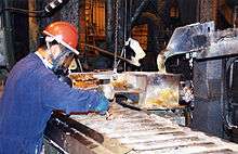
Lead–acid battery recycling is one of the most successful recycling programs in the world. In the United States 99% of all battery lead was recycled between 2009 and 2013.[39] An effective pollution control system is a necessity to prevent lead emission. Continuous improvement in battery recycling plants and furnace designs is required to keep pace with emission standards for lead smelters.
Additives
Chemical additives have been used ever since the lead–acid battery became a commercial item, to reduce lead sulfate build up on plates and improve battery condition when added to the electrolyte of a vented lead–acid battery. Such treatments are rarely, if ever, effective.[40]
Two compounds used for such purposes are Epsom salts and EDTA. Epsom salts reduces the internal resistance in a weak or damaged battery and may allow a small amount of extended life. EDTA can be used to dissolve the sulfate deposits of heavily discharged plates. However, the dissolved material is then no longer available to participate in the normal charge/discharge cycle, so a battery temporarily revived with EDTA will have a reduced life expectancy. Residual EDTA in the lead–acid cell forms organic acids which will accelerate corrosion of the lead plates and internal connectors.
The active materials change physical form during charge/discharge, resulting in growth and distortion of the electrodes, and shedding of electrode into the electrolyte. Once the active material has fallen out of the plates, it cannot be restored into position by any chemical treatment. Similarly, internal physical problems such as cracked plates, corroded connectors, or damaged separators cannot be restored chemically.
Corrosion problems
Corrosion of the external metal parts of the lead–acid battery results from a chemical reaction of the battery terminals, lugs and connectors.
Corrosion on the positive terminal is caused by electrolysis, due to a mismatch of metal alloys used in the manufacture of the battery terminal and cable connector. White corrosion is usually lead or zinc sulfate crystals. Aluminum connectors corrode to aluminum sulfate. Copper connectors produce blue and white corrosion crystals. Corrosion of a battery's terminals can be reduced by coating the terminals with petroleum jelly or a commercially available product made for the purpose.[41]
If the battery is over-filled with water and electrolyte, thermal expansion can force some of the liquid out of the battery vents onto the top of the battery. This solution can then react with the lead and other metals in the battery connector and cause corrosion.
The electrolyte can weep from the plastic-to-lead seal where the battery terminals penetrate the plastic case.
Acid fumes that vaporize through the vent caps, often caused by overcharging, and insufficient battery box ventilation can allow the sulfuric acid fumes to build up and react with the exposed metals.
Maintenance precautions
Ammonia can neutralize spilled battery acid. Surplus ammonia and water evaporate, leaving an ammonium sulfate residue. Sodium bicarbonate (baking soda) is also commonly used for this purpose.
Sizing nomenclature
With the broad range of possible electrical attributes, a part number nomenclature is used by many battery manufacturers to convey basic information such as voltage, ampere-hour capacity, and terminals.[42] The format follows a pattern such as <mfg><voltage><capacity>.
| Part number | Manufacturer | Voltage (V) | Capacity (Ah) |
|---|---|---|---|
| AP12-24 | Avon Battery | 12 | 24.0 |
| NB12-18HR | National Battery | 12 | 18.0 |
| TB12100 | Tenergy | 12 | 10.0 |
| CBL18-12 | Canbat Batteries | 12 | 18.0 |
| SP12-18HR | Sigmas Battery Tek | 12 | 18.0 |
| UB12180 | Universal Power Group | 12 | 18.0 |
Some vendors append a suffix, indicating the terminal types, terminal locations, and battery dimensions. Batteries for passenger motor vehicles usually use BCI sizing nomenclature.[43]
See also
References
- ↑ Panasonic, Panasonic LC-R1233P (PDF)
- 1 2 3 PowerSonic, PS and PSG General Purpose Battery Specifications, retrieved January 2014 Check date values in:
|access-date=(help) - ↑ "Trojan Product Specification Guide" (PDF). Retrieved January 2014. Check date values in:
|access-date=(help) - ↑ PowerSonic, Technical Manual (PDF), p. 19, retrieved January 2014 Check date values in:
|access-date=(help) - ↑ Cowie, Ivan (13 January 2014). "All About Batteries, Part 3: Lead-Acid Batteries". UBM Canon. Retrieved 3 November 2015.
- ↑ PowerSonic, PS-260 Datasheet (PDF), retrieved January 2014 Check date values in:
|access-date=(help) - ↑ Crompton, Thomas Roy (2000), Battery Reference Book, Newnes
- 1 2 3 4 5 Linden, David; Reddy, Thomas B., eds. (2002). Handbook Of Batteries (3rd ed.). New York: McGraw-Hill. p. 23.5. ISBN 0-07-135978-8.
- ↑ http://lead-acid.com/lead-acid-battery-history.shtml "The History of the Lead Acid Battery" retrieved 2014 Feb 22
- ↑ "Gaston Planté (1834-1889)", Corrosion-doctors.org; Last accessed on Jan 3, 2007
- ↑ For one example account of the importance of battery SG to submariners, see Ruhe, William J. (1996). War in the Boats: My World War II Submarine Battles. Brassey's. p. 112. ISBN 1-57488-028-4.
- ↑ http://www.windsun.com/Batteries/Battery_FAQ.htm#Battery%20Voltages Battery voltages
- ↑ "Recommended voltage settings for 3 phase charging of flooded lead acid batteries.", Rolls Battery, Retrieved on 17 April 2015.
- ↑ "Preventive Maintenance, Charging and Equalization", Rolls Battery, Retrieved on 17 April 2015.
- ↑ "Handbook for stationary lead-acid batteries (part 1: basics, design, operation modes and applications), page 65", GNB Industrial Power, a division of Exide Technologies, Edition 6, February 2012
- 1 2 Moderne Akkumulatoren, Page 55, ISBN 3-939359-11-4
- ↑ "Sealed lead acid battery charging basic", Powerstream, Retrieved on 17 April 2015.
- ↑ "Sealed lead acid batteries technical manual", Dynamis Batterien, Page 9, Version 04.12.2006 retrieved on 17 April 2015.
- 1 2 "Opportunity charging traction batteries - Information leaflet 10e, December 2011", ZVEI, Page 2, Retrieved on 17 April 2015.
- ↑ "Hydrogen gas management for flooded lead acid batteries", Mesa Technical Associates Inc. and Hoppecke Batterien GmbH & Co KG, Page 1, Retrieved on 17 April 2015.
- ↑ "Gassing and ventilation", cdtechno.com, Page 2, Retrieved on 17 April 2015.
- ↑ Dell, Ronald; David Anthony; James Rand (2001). Understanding Batteries. Royal Society of Chemistry. ISBN 0-85404-605-4.
- ↑ http://cdn.intechopen.com/pdfs-wm/9712.pdf
- ↑ http://www.labatscience.com/2_1_4_8.html
- ↑ United States Patent 5,948,567
- ↑ Introduction to Deep Cycle Batteries in RE Systems
- ↑ Cowlishaw, M.F. (December 1974). "The Characteristics and Use of Lead-Acid Cap Lamps" (PDF). Trans. British Cave Research Association. 1 (4): 199–214.
- ↑ "Battery FAQ" at Northern Arizona Wind & Sun, visited 2006-07-23
- ↑ Saslow, Wayne M. (2002). Electricity, Magnetism, and Light. Toronto: Thomson Learning. pp. 302–4. ISBN 0-12-619455-6.
- ↑ Sudhan S. Misra (25 May 2007). "Advances in VRLAnext term battery technology for telecommunications". Journal of Power Sources. 168 (1): 40–8. doi:10.1016/j.jpowsour.2006.11.005.
- ↑ Paper on recent VRLA developments from the Japanese Technical Center (SLI), Yuasa Corporation
- ↑ EU Aviation News website tells about history, usage and recent developments for VRLA.
- ↑ J W Simms. The Boy Electrician. George G Haerrap & Co. p. 65.
- ↑ Equalize charging can prevent sulfation if performed prior to the lead sulfate forming crystals. Broussely, Michel; Pistoia, Gianfranco, eds. (2007). Industrial applications of batteries: from cars to aerospace and energy storage. Elsevier. pp. 502–3. ISBN 0-444-52160-7.
- ↑ "Sulfation Remedies Demystified".
- ↑ Henry A. Catherino; Fred F. Feres; Francisco Trinidad (2004). "Sulfation in lead–acid batteries" (PDF). Journal of Power Sources. 129: 113–120. doi:10.1016/j.jpowsour.2003.11.003.
- ↑ "TOXICOLOGICAL PROFILE FOR LEAD" (pdf). USA: CDC Agency for Toxic Substances and Disease Registry. August 2007: 31. Retrieved 2013-09-26.
These data suggest that certain subtle neurobehavioral effects in children may occur at very low PbBs. (PbB means lead blood level)
|chapter=ignored (help) - ↑ DeCicco, John M.; Kliesch, James. ACEEE's Green Book: The Environmental Guide to Cars and Trucks. ISBN 0-918249-45-7.
- ↑ "Battery Council International." (PDF). Battery Council. Retrieved 26 August 2014.
- ↑ http://museum.nist.gov/exhibits/adx2/partii.htm A dispute on battery additives when Dr. Vinal of the National Bureau of Standards reported on this for the National Better Business Bureau.
- ↑ Horst Bauer (ed.) Automotive Handbook 4th Edition, Robert Bosch GmBH, 1996, ISBN 0-8376-0333-1, page 805
- ↑ "Battery Terminals". Retrieved 2013-05-31.
- ↑ "BCI Group Numbers, and Dimensional Specifications". Archived from the original on 2013-06-04. Retrieved 2013-05-31.
- General
- Lead Acid Battery Desulfator (Home Power #77 June/July 2000)
- Battery Plate Sulfation (MagnaLabs)
- Battery Desulfation
- Lead Acid Batteries
- DC Supply! (April 2002)
- Some Technical Details on Lead Acid Batteries
External links
| Wikimedia Commons has media related to Lead-acid batteries. |
- Battery Council International (BCI), lead–acid battery manufacturers' trade organization.
- Car and Deep Cycle Battery Frequently Asked Questions
- Case Studies in Environmental Medicine – Lead Toxicity
- Lead Acid Battery Desulfator (Home Power #77 June/July 2000)
- Battery Desulfation
| Types |  | |
|---|---|---|
| Cell parts | ||