Linear encoder

.jpg)
A linear encoder is a sensor, transducer or readhead paired with a scale that encodes position. The sensor reads the scale in order to convert the encoded position into an (Analog signal) analog or digital signal, which can then be decoded into position by a digital readout (DRO) or motion controller.
The encoder can be either incremental or absolute. Motion can be determined by change in position over time. Linear encoder technologies include optical, magnetic, inductive, capacitive and eddy current. Optical technologies include shadow, self imaging and interferometric. Linear encoders are used in metrology instruments, motion systems and high precision machining tools ranging from digital calipers and coordinate measuring machines to stages, CNC Mills, manufacturing gantry tables and semiconductor steppers.
Physical principle
Linear encoders are transducers that exploit many different physical properties in order to encode position:
Scale/reference based
Optical
Optical linear encoders[1][2] dominate the high resolution market and may employ shuttering/Moiré, diffraction or holographic principles. Optical encoders are the most accurate of the standard styles of encoders, and the most commonly used in industrial automation applications. When specifying an optical encoder, it’s important that the encoder has extra protection built in to prevent contamination from dust, vibration and other conditions common to industrial environments.[3] Typical incremental scale periods vary from hundreds of micrometers down to sub-micrometer. Interpolation can provide resolutions as fine as a nanometre.
Light sources used include infrared LEDs, visible LEDs, miniature light-bulbs and laser diodes.
Magnetic
Magnetic linear encoders[4] employ either active (magnetized) or passive (variable reluctance) scales and position may be sensed using sense-coils, Hall effect or magnetoresistive readheads. With coarser scale periods than optical encoders (typically a few hundred micrometers to several millimeters) resolutions in the order of a micrometer are the norm.
Capacitive
Capacitive linear encoders work by sensing the capacitance between a reader and scale. Typical applications are digital calipers. One of the disadvantages is the sensitivity to uneven dirt, which can locally change the relative permittivity.
Inductive
Inductive technology is robust to contaminants, allowing calipers and other measurement tools that are coolant-proof.[5] A well known application of the inductive measuring principle is the Inductosyn.[6]
Eddy current
US Patent 3820110, "Eddy current type digital encoder and position reference", gives an example of this type of encoder, which uses a scale coded with high and low permeability, non-magnetic materials, which is detected and decoded by monitoring changes in inductance of an AC circuit that includes an inductive coil sensor. Maxon makes an example (rotary encoder) product (the MILE encoder).[7]
Without scales
Optical image sensor
The sensors are based on an image correlation method. The Sensor takes subsequent pictures from the surface being measured and compares the images for displacement.[8] Resolutions down to 1 nm are possible.[9]
Applications
There are two main areas of application for linear encoders:
Measurement
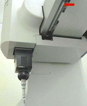
Measurement application include coordinate-measuring machines (CMM), laser scanners, calipers, gear measurement,[10] tension testers,[11] and digital read outs (DROs).
Motion systems
Servo controlled motion systems employ linear encoder so as to provide accurate, high-speed movement. Typical applications include robotics, machine tools, pick-and-place PCB assembly equipment; semiconductors handling and test equipment, wire bonders, printers and digital presses.[12]
Output signal formats
Incremental signals
Linear encoders can have analog or digital outputs.
Analog

The industry standard, analog output for linear encoders is sine and cosine quadrature signals. These are usually transmitted differentially so as to improve noise immunity. An early industry standard was 12 µA peak-peak current signals but more recently this has been replaced with 1V peak to peak voltage signals. Compared to digital transmission, the analog signals' lower bandwidth helps to minimise emc emissions.
Quadrature sine/cosine signals can be monitored easily by using an oscilloscope in XY mode to display a circular Lissajous Figure. Highest accuracy signals are obtained if the Lissajous Figure is circular (no gain or phase error) and perfectly centred. Modern encoder systems employ circuitry to trim these error mechanisms automatically. The overall accuracy of the linear encoder is a combination of the scale accuracy and errors introduced by the readhead. Scale contributions to the error budget include linearity and slope (scaling factor error). Readhead error mechanisms are usually described as cyclic error or sub-divisional error (SDE) as they repeat every scale period. The largest contributor to readhead inaccuracy is signal offset, followed by signal imbalance (ellipticity) and phase error (the quadrature signals not being exactly 90° apart). Overall signal size does not affect encoder accuracy, however, signal-to-noise and jitter performance may degrade with smaller signals. Automatic signal compensation mechanisms can include automatic offset compensation (AOC), automatic balance compensation (ABC) and automatic gain control (AGC). Phase is more difficult to compensate dynamically and is usually applied as one time compensation during installation or calibration. Other forms of inaccuracy include signal distortion (frequently harmonic distortion of the sine/cosine signals).
Digital

Many linear encoders interpolate the analogue sine/cosine signals in order to sub-divide the scale period, providing a higher measurement resolution. The output of the interpolation process is quadrature squarewaves – the distance between edges of the two channels being the resolution of the encoder. The reference mark or index pulse will also be processed digitally and will be a pulse, usually one to four units-of-resolution wide.
The major advantage of encoders with built-in interpolation and digital signal transmission is improved noise immunity. However, the high frequency, fast edge speed signals may produce more emc emissions.
Incremental encoders with built-in digital processing make it possible to transmit position to any subsequent electronics such as a position counter.
Absolute reference signals
As well as analog or digital incremental output signals, linear encoders can provide absolute reference or positioning signals.
Reference mark
Most incremental, linear encoders can produce an index or reference mark pulse providing a datum position along the scale for use at power-up or following a loss of power. This index signal must be able to identify position within one, unique period of the scale. The reference mark may comprise a single feature on the scale, an autocorrelator pattern (typically a Barker code) or a chirp pattern.
Distance coded reference marks (DCRM) are placed onto the scale in a unique pattern allowing a minimal movement (typically moving past two reference marks) to define the readhead's position. Multiple, equally spaced reference marks may also be placed onto the scale such that following installation, the desired marker can either be selected - usually via a magnet or optically or unwanted ones deselected using labels or by being painted over.
Absolute code
With suitably encoded scales (multitrack, vernier, digital code, or pseudo-random code) an encoder can determine its position without movement or needing to find a reference position. Such absolute encoders also communicate using serial communication protocols. Many of these protocols are proprietary (e.g., Fanuc, Mitsubishi, FeeDat (Fagor Automation), EnDat, DriveCliq, Panasonic, Yaskawa) but open standards such as BiSS[13] are now appearing, which avoid tying users to a particular supplier.
Limit switches
Many linear encoders include built-in limit switches; either optical or magnetic. Two limit switches are frequently included such that on power-up the controller can determine if the encoder is at an end-of-travel and in which direction to drive the axis.
Physical arrangement and protection
Linear encoders may be either enclosed or open. Enclosed linear encoders are employed in dirty, hostile environments such as machine-tools. They typically comprise an aluminium extrusion enclosing a glass or metal scale. Flexible lip seals allow an internal, guided readhead to read the scale. Accuracy is limited due to the friction and hysteresis imposed by this mechanical arrangement.
For the highest accuracy, lowest measurement hysteresis and lowest friction applications, open linear encoders are used.
Linear encoders may use transmissive (glass) or reflective scales, employing Ronchi or phase gratings. Scale materials include chrome on glass, metal (stainless steel, gold plated steel, Invar), ceramics (Zerodur) and plastics. The scale may be self-supporting, thermally mastered to the substrate (via adhesive or adhesive tape) or track mounted. Track mounting may allow the scale to maintain its own coefficient of thermal expansion and allows large equipment to be broken down for shipment.
Encoder terms
- Resolution
- Repeatability
- Hysteresis
- Signal-to-noise ratio/noise/jitter
- Lissajous figure
- Quadrature
- Index/reference mark/datum/fiducial
- Distance coded reference marks (DCRM)
http://www.heidenhainencoders.co.uk/
http://www.fagorautomation.de/en/
See also
References
- ↑ http://www.microesys.com/products
- ↑ http://www.renishaw.com/en/6433.aspx
- ↑ http://www.motioncontroltips.com/2013/11/04/understanding-encoders/ Understanding Encoders Motion Control Tips: A Design World Resource
- ↑ "Archived copy". Archived from the original on 2009-10-10. Retrieved 2009-10-30.
- ↑ "Archived copy" (PDF). Archived from the original (PDF) on 2013-11-03. Retrieved 2011-11-15.
- ↑ http://www.ruhle.com/bar_scale.htm
- ↑ http://www.maxonmotor.com/downloads/Flyer_EC6_MILE_e_03.09.pdf
- ↑ "Archived copy". Archived from the original on 2012-04-25. Retrieved 2011-11-02.
- ↑ "Archived copy" (PDF). Archived from the original (PDF) on 2011-10-13. Retrieved 2011-11-15.
- ↑ "Archived copy". Archived from the original on 2009-03-28. Retrieved 2009-10-28.
- ↑ http://www.instron.co.uk/wa/product/Tension-Testers.aspx
- ↑ "Archived copy". Archived from the original on 2009-10-10. Retrieved 2009-10-29.
- ↑ http://www.biss-interface.com/
Books
- David S. Nyce: Linear Position Sensors: Theory and Application, New Jersey, John Wiley & Sons Inc. (2003)
- Walcher Hans: Position Sensing: Angle and Distance Measurement for Engineers, Butterworth Heinemann (1994)