Defect detector
A defect detector is a device used on railroads to detect axle and signal problems in passing trains. The detectors are normally integrated into the tracks and often include sensors to detect several different kinds of problems that could occur. Defect detectors were one invention which enabled American railroads to eliminate the caboose at the rear of the train, as well as various station agents stationed along the route to detect unsafe conditions. The use of defect detectors has since spread to other overseas railroads.
History
Before the advent of automated detectors, it was the responsibility of on-board train crew and track-side workers to visually inspect trains for defects, and then to bring the train to a halt, if a defect were observed. To detect "hotboxes," i.e., overheating bearings, they would look for oil smoke during the day or a red glow at night. As early as the 1940s, automatic defect detectors were installed to improve upon the manual process. Hotboxes could be detected using new infrared light sensors; high and wide loads by wires outlining the clearance envelope, and dragging equipment through "brittle bars" - frangible bars mounted between the rails. The detectors would transmit their data via wired links to remote read-outs in stations, offices or interlocking towers. A stylus-and-cylinder gauge would record a reading for every axle; if a journal were too hot, or if some other defect were detected, the offending axle would register a sharp spike on the graph. An alarm would sound as well, and the employee on duty at that locality would either use manual signals or the signaling system to bring the train to a halt and, if possible, to inform the crew of the approximate location of the problem.
Early line-side defect detectors were typically housed in concrete bungalows, roughly every 10–20 miles (16–32 km). When the train cleared the detector, a fixed white light would be displayed from the detector bungalow, unless a defect were found, in which case, the light would either flash or would not turn on at all. The crew stationed at the rear of the train would observe this light and, if a defect were indicated, stop the train and have the conductor report to the bungalow to examine an (analogue) paper-tape readout.
The first computerized detectors used fixed-display boards. These had a three-character numeric display and a number of indicator lights relating to the nature of defects. A number would be displayed in lights on the board after the train had cleared the detector. The number "000" meant there were no defects; any other number warned of a defect at the corresponding axle. If several were detected, small white lights on the top and bottom could also be displayed (depending which light was on ) to inform the rear-end crews of multiple problems and to indicate the type of defect in each case. Nevertheless, the conductor was still required to go into the bungalow and read specific information about the nature of the defect.
Seaboard Air Line was the first railroad to install talking defect detectors. Beginning in the 1960s, their train crews could hear the results of hotbox and dragging-equipment checks spoken over their radios in the engine cab and in the caboose. Over the years, as the use of this technology accelerated, the rear-end crews were eliminated from most freight trains. For example, computerized, talking detectors allowed crews to interact with the detector using a touch tone function on their radios to recall the latest defect report. This eliminated any need for crews to walk to the detector location to confirm the radio reading.
Today
Beginning in the 1980s many North American Class I railroads began adding radio transmitters and mechanical voices to their defect detectors; as trains passed detectors, the mechanical or pre-recorded voice would sound out on the railroad's main road radio channel that a train has passed and note any defects that were found. Most often, after a train has passed such an equipped detector, the mechanical voice will report the railroad name, milepost or location, track number (if applicable), number of axles on the train that passed and the phrase "no defects" to indicate that no problems were detected on the train. Sometimes the location's ambient temperature and train speed are also noted by the mechanical voice. When a problem is detected, the mechanical voice will often start with a long, high pitch alarm tone followed by a description of the problem and the axle position within the train where the problem occurred. Crews can use their touch-tone hand radios to get the detector to repeat error messages. Defect detectors that are equipped with such a mechanical voice are often called talking detectors by railfans.
To this day some rail lines, mostly passenger routes with a very high traffic density, maintain centralized readout, non-talking detectors. This is due to the large and confusing volume of radio traffic a talking detector would generate. When an error signal is received a dispatcher or operator will contact the train via radio manually transmitting the error message and required action (like slow down, stop at next station or immediately stop).
Today defect detectors are often incorporated in monitoring platforms that are primarily used by railroads to more closely monitor the status of their trains. In countries where rail transport has been liberalised, infrastructure companies use defect detectors to check the quality and status of different train owners. The main concern of the infra owner is protecting their asset and preventing excessive damage. However, studies have been conducted to see whether defect detectors can be used to issue "penalties" to track-unfriendly vehicles (or provide discounts to those operators with track-friendly vehicles).[1]
Talking detectors are also used by railfans that are carrying scanners to listen in on the railroad's radio chatter. Railfans are often able to gauge where trains are by listening for the detectors' transmissions; in doing so, the railfans can more precisely predict when a train will pass a specific location to improve their chances of photographing the trains.
Limitations
Like all train safety equipment, defect detectors are not foolproof. They can be defeated by human error. A 2003 accident in Canada provides an illustration.[2]
One night in October of that year, a Canadian Pacific freight was operating eastbound on the Kaministiquia Subdivision between Ignace and Thunder Bay, Ontario. Shortly after departing the former location, the crew received a "no defects" report from a hot box detector. Similar messages were received from two other detectors passed later on.[3]
Shortly after the second one, the crew considered calling their dispatcher on the radio about a possible upcoming meet but decided against it. The engineer, who had changed channels on the cab radio in preparation, inadvertently put it on the wrong channel when he switched it back afterwards.[3] The next detector the train passed detected a hot bearing and reported this to the crew; however the warning was unheard since the radio was on the wrong channel.[2]
Six miles (9.7 km) down the line, the engineer noticed some problems with the train's handling. After stopping it near Carlstadt, the crew went out to inspect it; they found that rapid burnoff had occurred on the axle in question and several cars had derailed after the wheel came off the axle in question. Portions of the bearing were found as far back as the detector that had sounded the alarm.[3]
"Once the crew missed the alarm message," the Transportation Safety Board of Canada wrote in its report on the accident, "the defence provided by the HBD was no longer of any value." It found that if the crew had reset the radio correctly, they would have heard the warning and stopped the train at that point per procedure (the placement of the radio within the cab and the crew's fatigue were also found to be contributing factors to the oversight). It recommended that CP follow the example of Canadian National, its primary competitor, and implement a central monitoring system for its defect detector network that would enable the railroad to verify that crews had received warnings.[3]
Sensors
The sensors installed at defect detector locations can include and are explained:
- Hotbox or Hot Bearing Detectors
Two infrared eyes sit on each side of the tracks looking up at the train's bearings. They register the radiation from every journal that passes over them. If a bearing reaches the maximum temperature for safe travel, the detector will flag and count it as a defect.
- Dragging Equipment Detectors
A column of cones sits across the whole width of the railroad (just like a cross tie) attached to a switch. Anything dragging from the train will hit this cone, thus pushing it back, thus breaking a contact. It then returns to its normal position to prepare for anything else that might be dragging under the train. The detector will register this action and flag it as a defect. Brittle bars are still used elsewhere, but still have to be repaired. Over time, dragging equipment detectors metal flaps need to be replaced because of extensive damage to them. Single use systems typically involve a frangible engagement bar or a stainless steel wire/braid strung between the rails and typically outside the rails as well, fastened to the sleepers. If the bar or braid is hit by something it breaks, and the circuit break alerts that there is a dragging item. Auto-resetting systems typically involve a pivot pin system to allow the target to reset itself after a hit.
- High Car or Shifted Load Detectors
Infrared beams are placed horizontally above the track (high car) or vertically next to the track (shifted load). Anything that breaks the beam will be counted as a defect. High car is placed anywhere an excess height car could be routed onto a low clearance line. Shifted load is mainly found on railroads where double-stack trains are prevalent as the containers may become misaligned and present a hazard to bridge trusses or tunnel walls.
- Wheel Impact Detectors (often placed at the entrances of delicate high speed track like Amtrak's Northeast Corridor)
Wheel sensors along the tracks feel for flat spots on the train's wheels. Any flat wheel that becomes too dangerous to travel on (a big flat spot on the train wheel) will be counted as a defect. Typically, these systems utilise accelerometers, strain gauges, or fibre optic methods. A wheel impact load detector (WILD) measures impacts, but does not normalise these impact measurements against anything: simply the impact reading. They do not attempt to cater for differences in sprung mass, as they are measuring wheel defect impact, rather than impact load. Therefore, the same wheel defect will register a much larger impact when a wagon is loaded, versus when it is empty. A wheel condition monitoring detector monitors the condition of the wheel independent of sprung mass – independent of load. They do this by subtracting the wheel mass to get the normalised impact value. These systems are therefore typically better at detecting smaller defects with greater resolution.
- Sliding/Hot Wheel Detector
Typically a length of side looking infrared detectors that can detect if a wheel has locked up and is not sliding along the track or has had the brakes lock up causing the entire wheel to heat up.
- Vehicle Imbalance Detectors (side-to-side and end-to-end)
These detectors are typically a crude weighbridge and/or WILD system, as they are only concerned with measuring weight differentials. They do not have to be as accurate as proper weighbridge or WILD systems, but just accurate enough to be able to average the weight of bogies during a train pass to calculate the relative balance of wagons, to establish if one rail is loaded unacceptably greater (in percentage) than the other. This is typically not performed on empty wagons because of the significant percentage imbalances that can be caused by fluctuations in weight due to bogie tracking geometry or hunting issues, which in terms of weight differentials are relatively accentuated compared to when a wagon is loaded.
- Clearance Gauge Monitors
These detectors can use a variety of sensors (video, laser, infrared), but typically they are a safety curtain arrangement: a gantry over the rail with sensors to detect anything outside the Clearance Gauge. They therefore check the envelope of safety and alert if anything is detected outside of it.
- Low Hose Detectors (air hose)
These systems are different to dragging equipment detectors, which are looking for anything dragging from the train connecting with the sleepers. Low Hose detectors are looking specifically between two wagons, to measure the droop of the brake hoses. The brake hoses need a bit of droop, but too much and they can hit or dislodge. Typically, these systems employ a vertical bar installed on one side of the track, with infrared sensors pointed across the track at a mate bar with receivers installed pointed back at the infrared beams. When a train goes past, the infrared sensors are looking in the coupling area specifically, and will alert if anything is detected in the area that is lower than acceptable.
- Video/Image Inspection Systems
These systems rely on an array of video devices in various locations between the rails and either side of the track, looking for particular bogie components (such as brake beam, springs, friction wedges, etc) and this data is then put through image analysis to determine if there are maintenance issues.
- Wheel Profile Systems
These are laser arrays installed between or in place of a sleeper. They point up at the wheel profile and measure the profile shape specifically, taking various measurements of angles and lengths. The systems also give differential measurements for the two wheels of a wheelset.
- Bogie Performance Detectors
Bogie performance detectors monitor bogie tracking geometry, and hunting (instability) behaviour. Bogie tracking geometry includes tracking position and angle of attack on a per-axle basis, as well as rotation, shift, inter-axle misalignment, and tracking error on a per-bogie basis. Bogie performance detectors can provide early detection of bogie defects, and early warning of derailment risks through flange climb or rail break.[4] Bogie performance detectors most often use optical methods, and are installed adjacent to the track with wheel sensors clamped to the rails.
- Rail Break Monitors
These detectors either inject frequencies into the rail, or rely on existing track circuits, to detect rail breaks. These detectors are most commonly used by high speed networks.
- Rail Temperature Monitors
These detectors are a mesh of small detectors installed against a particular stretch of rail. The detectors are typically a mix of temperature sensors and strain gauges (so measure in degrees Celsius and kilonewtons force). They measure temperature and stress/tension on the rail, to make sure these measures do not go outside the bounds of structural integrity. These systems are initially calibrated to a particular ‘neutral state’ but measuring the rail with neutral compression (no pulling or pushing) and an agreed neutral ambient temperature. The system then measures the rail to detect if these parameters get too far from neutral state, and will alert if the rail is approaching a breach of structural integrity.
- Ground Based Noise (GBN)
This is a combination of accelerometers on the track, and another accelerometer installed in the bedrock next to the track. The correlation of these measurements indicates how much track-born noise is propagating through the ballast into the bedrock strata. This correlates directly with the noise levels experienced by surrounding area. These systems are commonly installed near or inside tunnels.
- Brake Block Detectors
These are distinct from generic video imaging systems, as they are dedicated to specifically imaging the band above the rail that contains the brake shoe. The system identifies the back plate of the brake shoe, and then works out how much brake block is left in millimetres. If the system detects no brake block beyond the back plate, the system typically identifies the pad as missing.
- Weighing in Motion sensors for axle loads or imbalances.
- Wide-load Detectors
A bridge spans the railroad with two laser beams that shine down on each side of the passing train. Anything that cuts through the beam will be counted as a defect. This sensor may also be integrated into the high car detector.
- Structure gauge & loading gauge
- Hot-Wheel Detection (caused by sticking brake)
Gallery
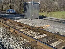
 A CSX defect detector housed in the far equipment shed.
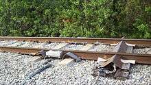
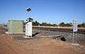 Overview of a wheel impact detector installation
See also
References
- ↑ Andrew Grantham "Raising loads and lowering charges", European Railway Review,1 November 2003.
- 1 2 Bibel, George (2012). Train Wreck: The Forensics of Rail Disasters. Baltimore, MD: Johns Hopkins University Press. p. 189. ISBN 9781421405902. Retrieved April 2, 2016.
- 1 2 3 4 "Report Number R03W0169" (PDF). Transportation Safety Board of Canada. July 7, 2004. Retrieved April 2, 2016.
- ↑ Bladon, Paul (2015). "The Challenges of Integrating Novel Wayside Rolling Stock Monitoring Technologies: A Case Study". Perth, Australia: International Heavy Haul Association. Retrieved June 21, 2015.
External links
| Wikimedia Commons has media related to Defect detector. |
- Audio: CONRAIL Talking Detector in Depew, New York (.wav file)
- Audio: CONRAIL Talking Detector in Lancaster, New York (.wav file)
- Photos: 'Wheel Impact Load Detector' at Lara, Australia
- Western New York Railway Historical Society - (more talking detector audio clips)