Jitter
In electronics and telecommunications, jitter is the deviation from true periodicity of a presumably periodic signal, often in relation to a reference clock signal. In clock recovery applications it is called timing jitter.[1] Jitter is a significant, and usually undesired, factor in the design of almost all communications links.
Jitter can be quantified in the same terms as all time-varying signals, e.g., root mean square (RMS), or peak-to-peak displacement. Also like other time-varying signals, jitter can be expressed in terms of spectral density.
Jitter period is the interval between two times of maximum effect (or minimum effect) of a signal characteristic that varies regularly with time. Jitter frequency, the more commonly quoted figure, is its inverse. ITU-T G.810 classifies jitter frequencies below 10 Hz as wander and frequencies at or above 10 Hz as jitter.[2]
Jitter may be caused by electromagnetic interference and crosstalk with carriers of other signals. Jitter can cause a display monitor to flicker, affect the performance of processors in personal computers, introduce clicks or other undesired effects in audio signals, and cause loss of transmitted data between network devices. The amount of tolerable jitter depends on the affected application.
Jitter metrics
For clock jitter, there are three commonly used metrics: absolute jitter, period jitter, and cycle to cycle jitter.
- Absolute jitter
- The absolute difference in the position of a clock's edge from where it would ideally be.
- Period jitter (aka cycle jitter)
- The difference between any one clock period and the ideal or average clock period. Period jitter tends to be important in synchronous circuitry such as digital state machines where the error-free operation of the circuitry is limited by the shortest possible clock period (average period less maximum cycle jitter), and the performance of the circuitry is set by the average clock period. Hence, synchronous circuitry benefits from minimizing period jitter, so that the shortest clock period approaches the average clock period.
- Cycle-to-cycle jitter
- The difference in duration of any two adjacent clock periods. It can be important for some types of clock generation circuitry used in microprocessors and RAM interfaces.
In telecommunications, the unit used for the above types of jitter is usually the Unit Interval (abbreviated UI) which quantifies the jitter in terms of a fraction of the ideal period of a bit. This unit is useful because it scales with clock frequency and thus allows relatively slow interconnects such as T1 to be compared to higher-speed internet backbone links such as OC-192. Absolute units such as picoseconds are more common in microprocessor applications. Units of degrees and radians are also used.
If jitter has a Gaussian distribution, it is usually quantified using the standard deviation of this distribution (aka. RMS). Often, jitter distribution is significantly non-Gaussian. This can occur if the jitter is caused by external sources such as power supply noise. In these cases, peak-to-peak measurements are more useful. Many efforts have been made to meaningfully quantify distributions that are neither Gaussian nor have meaningful peaks (which is the case in all real jitter). All have shortcomings but most tend to be good enough for the purposes of engineering work. Note that typically, the reference point for jitter is defined such that the mean jitter is 0.
In networking, in particular IP networks such as the Internet, jitter can refer to the variation (statistical dispersion) in the delay of the packets.
Types
Random jitter
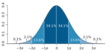
Random Jitter, also called Gaussian jitter, is unpredictable electronic timing noise. Random jitter typically follows a Gaussian distribution or Normal distribution. It usually follows this pattern because most noise or jitter in an electrical circuit is caused by thermal noise, which has a Gaussian distribution. Another reason for random jitter to have a distribution like this is due to the central limit theorem. The central limit theorem states that composite effect of many uncorrelated noise sources, regardless of the distributions, approaches a Gaussian distribution.[3] One of the main differences between random and deterministic jitter is that deterministic jitter is bounded and random jitter is unbounded.
Deterministic jitter
Deterministic jitter is a type of clock timing jitter or data signal jitter that is predictable and reproducible. The peak-to-peak value of this jitter is bounded, and the bounds can easily be observed and predicted. Deterministic jitter can either be correlated to the data stream (data-dependent jitter) or uncorrelated to the data stream (bounded uncorrelated jitter). Examples of data-dependent jitter are duty-cycle dependent jitter (also known as duty-cycle distortion) and intersymbol interference.
Deterministic jitter (or DJ) has a known non-Gaussian probability distribution.
| n | BER |
|---|---|
| 6.4 | 10−10 |
| 6.7 | 10−11 |
| 7 | 10−12 |
| 7.3 | 10−13 |
| 7.6 | 10−14 |
Total jitter
Total jitter (T) is the combination of random jitter (R) and deterministic jitter (D):
- T = Dpeak-to-peak + 2× n×Rrms,
in which the value of n is based on the bit error rate (BER) required of the link.
A common bit error rate used in communication standards such as Ethernet is 10−12.
Examples
Sampling jitter
In analog to digital and digital to analog conversion of signals, the sampling is normally assumed to be periodic with a fixed period—the time between every two samples is the same. If there is jitter present on the clock signal to the analog-to-digital converter or a digital-to-analog converter, the time between samples varies and instantaneous signal error arises. The error is proportional to the slew rate of the desired signal and the absolute value of the clock error. Various effects such as noise (random jitter), or spectral components (periodic jitter) can come about depending on the pattern of the jitter in relation to the signal. In some conditions, less than a nanosecond of jitter can reduce the effective bit resolution of a converter with a Nyquist frequency of 22 kHz to 14 bits.[4]
This is a consideration in high-frequency signal conversion, or where the clock signal is especially prone to interference.
Packet jitter in computer networks
In the context of computer networks, jitter is the variation in latency as measured in the variability over time of the packet latency across a network. A network with constant latency has no variation (or jitter).[5] Packet jitter is expressed as an average of the deviation from the network mean latency. However, for this use, the term is imprecise. The standards-based term is "packet delay variation" (PDV).[6] PDV is an important quality of service factor in assessment of network performance.
Compact disc seek jitter
In the context of digital audio extraction from compact discs, seek jitter causes extracted audio samples to be doubled-up or skipped entirely if the Compact Disc drive re-seeks. The problem occurs because the Red Book does not require block-accurate addressing during seeking. As a result, the extraction process may restart a few samples early or late, resulting in doubled or omitted samples. These glitches often sound like tiny repeating clicks during playback. A successful approach to correction in software involves performing overlapping reads and fitting the data to find overlaps at the edges. Most extraction programs perform seek jitter correction. CD manufacturers avoid seek jitter by extracting the entire disc in one continuous read operation, using special CD drive models at slower speeds so the drive does not re-seek.
A jitter meter is a testing instrument for measuring clock jitter values, and is used in manufacturing DVD and CD-ROM discs.
Due to additional sector level addressing added in the Yellow Book, CD-ROM data discs are not subject to seek jitter.
Video and image jitter
Video or image jitter occurs when the horizontal lines of video image frames are randomly displaced due to the corruption of synchronization signals or electromagnetic interference during video transmission. Model based dejittering study has been carried out under the framework of digital image/video restoration.[7]
Testing
Testing for jitter and its measurement is of growing importance to electronics engineers because of increased clock frequencies in digital electronic circuitry to achieve higher device performance. Higher clock frequencies have commensurately smaller eye openings, and thus impose tighter tolerances on jitter. For example, modern computer motherboards have serial bus architectures with eye openings of 160 picoseconds or less. This is extremely small compared to parallel bus architectures with equivalent performance, which may have eye openings on the order of 1000 picoseconds.
Testing of device performance for jitter tolerance often involves the injection of jitter into electronic components with specialized test equipment.
Jitter is measured and evaluated in various ways depending on the type of circuitry under test. For example, jitter in serial bus architectures is measured by means of eye diagrams, according to industry accepted standards. A less direct approach—in which analog waveforms are digitized and the resulting data stream analyzed—is employed when measuring pixel jitter in frame grabbers.[8] In all cases, the goal of jitter measurement is to verify that the jitter will not disrupt normal operation of the circuitry.
There are standards for jitter measurement in serial bus architectures. The standards cover jitter tolerance, jitter transfer function and jitter generation, with the required values for these attributes varying among different applications. Where applicable, compliant systems are required to conform to these standards.
Mitigation
Anti-jitter circuits
Anti-jitter circuits (AJCs) are a class of electronic circuits designed to reduce the level of jitter in a regular pulse signal. AJCs operate by re-timing the output pulses so they align more closely to an idealised pulse signal. They are widely used in clock and data recovery circuits in digital communications, as well as for data sampling systems such as the analog-to-digital converter and digital-to-analog converter. Examples of anti-jitter circuits include phase-locked loop and delay-locked loop. Inside digital to analog converters, jitter causes unwanted high-frequency distortions. In this case it can be suppressed with high fidelity clock signal usage.
Jitter buffers
Jitter buffers or de-jitter buffers are used to counter jitter introduced by queuing in packet switched networks so that a continuous playout of audio (or video) transmitted over the network can be ensured. The maximum jitter that can be countered by a de-jitter buffer is equal to the buffering delay introduced before starting the play-out of the mediastream. In the context of packet-switched networks, the term packet delay variation is often preferred over jitter.
Some systems use sophisticated delay-optimal de-jitter buffers that are capable of adapting the buffering delay to changing network jitter characteristics. These are known as adaptive de-jitter buffers and the adaptation logic is based on the jitter estimates computed from the arrival characteristics of the media packets. Adaptive de-jittering involves introducing discontinuities in the media play-out, which may appear offensive to the listener or viewer. Adaptive de-jittering is usually carried out for audio play-outs that feature a VAD/DTX encoded audio, that allows the lengths of the silence periods to be adjusted, thus minimizing the perceptual impact of the adaptation.
Dejitterizer
A dejitterizer is a device that reduces jitter in a digital signal. A dejitterizer usually consists of an elastic buffer in which the signal is temporarily stored and then retransmitted at a rate based on the average rate of the incoming signal. A dejitterizer is usually ineffective in dealing with low-frequency jitter, such as waiting-time jitter.
Filtering
A filter can be designed to minimize the effect of sampling jitter. For more information, see the paper by S. Ahmed and T. Chen entitled, "Minimizing the effects of sampling jitters in wireless sensors networks".
See also
- Buffer (telecommunication)
- Clock drift
- Dither
- Maximum time interval error
- Phase noise
- Pulse (signal processing)
References
- ↑ Wolaver, Dan H. (1991). Phase-Locked Loop Circuit Design. Prentice Hall. p. 211. ISBN 0-13-662743-9.
- ↑ "Application note 119" (PDF). Retrieved 2012-08-05.
- ↑ Chow, Daniel. "Jitter Visualization, Part 1: Random Jitter". UBM Tech. Retrieved 12 April 2013.
- ↑ Puente León, Fernando (2015). Messtechnik. Springer. p. 332f. ISBN 978-3-662-44820-5.
- ↑ Comer, Douglas E. (2008). Computer Networks and Internets. Prentice Hall. p. 476. ISBN 978-0-13-606127-4.
- ↑ Demichelis, C. (November 2002). IP Packet Delay Variation Metric for IP Performance Metrics (IPPM). IETF. RFC 3393. https://tools.ietf.org/html/rfc3393.
- ↑ Kang, Sung-Ha; Shen, Jianhong (Jackie) (2006). "Video Dejittering by Bake and Shake". Image and Vision Computing. 24 (2): 143–152. doi:10.1016/j.imavis.2005.09.022.
- ↑ Khvilivitzky, Alexander (2008). "Pixel Jitter in Frame Grabbers". Retrieved 2015-03-09.
-
 This article incorporates public domain material from the General Services Administration document "Federal Standard 1037C" (in support of MIL-STD-188).
Further reading
- Levin, Igor. Terms and concepts involved with digital clocking related to Jitter issues in professional quality digital audio
- Li, Mike P. Jitter and Signal Integrity Verification for Synchronous and Asynchronous I/Os at Multiple to 10 GHz/Gbps. Presented at International Test Conference 2008.
- Li, Mike P. A New Jitter Classification Method Based on Statistical, Physical, and Spectroscopic Mechanisms. Presented at DesignCon 2009.
- Liu, Hui, Hong Shi, Xiaohong Jiang, and Zhe Li. Pre-Driver PDN SSN, OPD, Data Encoding, and Their Impact on SSJ. Presented at Electronics Components and Technology Conference 2009.
- Miki, Ohtani, and Kowalski Jitter Requirements (Causes, solutions and recommended values for digital audio)
- Trischitta, Patrick R.; Varma, Eve L. (1989). Jitter in Digital Transmission Systems. Artech. ISBN 0-89006-248-X.
- Zamek, Iliya. SOC-System Jitter Resonance and Its Impact on Common Approach to the PDN Impedance. Presented at International Test Conference 2008.
External links
| Wikimedia Commons has media related to Jitter. |
| Wikibooks has a book on the topic of: Clock and Data Recovery/Introduction/Definition of (phase) jitter |
- Beating the jitter bug
- Jitter in VoIP - Causes, solutions and recommended values
- Jitter Buffer
- Definition of Jitter in a QoS Testing Methodology
- An Introduction to Jitter in Communications Systems
- Jitter Specifications Made Easy A Heuristic Discussion of Fibre Channel and Gigabit Ethernet Methods
- Jitter in Packet Voice Networks