Doppler radar

A Doppler radar is a specialized radar that uses the Doppler effect to produce velocity data about objects at a distance. It does this by bouncing a microwave signal off a desired target and analyzing how the object's motion has altered the frequency of the returned signal. This variation gives direct and highly accurate measurements of the radial component of a target's velocity relative to the radar. Doppler radars are used in aviation, sounding satellites, meteorology, radar guns,[1] radiology and healthcare (fall detection[2] and risk assessment, nursing or clinic purpose[3]), and bistatic radar (surface-to-air missile).
Partly because of its common use by television meteorologists in on-air weather reporting, the specific term "Doppler Radar" has erroneously become popularly synonymous with the type of radar used in meteorology. Most modern weather radars use the pulse-doppler technique to examine the motion of precipitation, but it is only a part of the processing of their data. So, while these radars use a highly specialized form of doppler radar, the term is much broader in its meaning and its applications.
Concept
Doppler effect
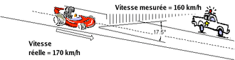
The Doppler effect (or Doppler shift), named after Austrian physicist Christian Doppler who proposed it in 1842, is the difference between the observed frequency and the emitted frequency of a wave for an observer moving relative to the source of the waves. It is commonly heard when a vehicle sounding a siren approaches, passes and recedes from an observer. The received frequency is higher (compared to the emitted frequency) during the approach, it is identical at the instant of passing by, and it is lower during the recession. This variation of frequency also depends on the direction the wave source is moving with respect to the observer; it is maximum when the source is moving directly toward or away from the observer and diminishes with increasing angle between the direction of motion and the direction of the waves, until when the source is moving at right angles to the observer, there is no shift.
Imagine a baseball pitcher throwing one ball every second to a catcher (a frequency of 1 ball per second). Assuming the balls travel at a constant velocity and the pitcher is stationary, the catcher catches one ball every second. However, if the pitcher is jogging towards the catcher, the catcher catches balls more frequently because the balls are less spaced out (the frequency increases). The inverse is true if the pitcher is moving away from the man. He catches balls less frequently because of the pitcher's backward motion (the frequency decreases). If the pitcher moves at an angle, but at the same speed, the frequency variation at which the receiver catches balls is less, as the distance between the two changes more slowly.
From the point of view of the pitcher, the frequency remains constant (whether he's throwing balls or transmitting microwaves). Since with electromagnetic radiation like microwaves frequency is inversely proportional to wavelength, the wavelength of the waves is also affected. Thus, the relative difference in velocity between a source and an observer is what gives rise to the doppler effect.[4]
Frequency variation
The formula for radar doppler shift is the same as that for reflection of light by a moving mirror.[5] There is no need to invoke Einstein's theory of special relativity, because all observations are made in the same frame of reference.[6] The result derived with c as the speed of light and v as the target velocity gives the shifted frequency () as a function of the original frequency () :


The "beat frequency", (Doppler frequency) (), is thus:[7]


Since for most practical applications of radar, , so . We can then write:


Technology

There are four ways of producing the Doppler effect. Radars may be:
- Coherent pulsed (CP),
- Pulse-Doppler radar,
- Continuous wave (CW), or
- Frequency modulation (FM).
Doppler allows the use of narrow band receiver filters that reduce or eliminate signals from slow moving and stationary objects. This effectively eliminates false signals produced by trees, clouds, insects, birds, wind, and other environmental influences. Cheap hand held Doppler radar may produce erroneous measurements.[8]
CW doppler radar only provides a velocity output as the received signal from the target is compared in frequency with the original signal. Early doppler radars included CW, but these quickly led to the development of frequency modulated continuous wave (FMCW) radar, which sweeps the transmitter frequency to encode and determine range.
With the advent of digital techniques, Pulse-Doppler radars (PD) became light enough for aircraft use, and doppler processors for coherent pulse radars became more common. That provides Look-down/shoot-down capability. The advantage of combining doppler processing with pulse radars is to provide accurate velocity information. This velocity is called range-rate. It describes the rate that a target moves toward or away from the radar. A target with no range-rate reflects a frequency near the transmitter frequency and cannot be detected. The classic zero doppler target is one which is on a heading that is tangential to the radar antenna beam. Basically, any target that is heading 90 degrees in relation to the antenna beam cannot be detected by its velocity (only by its conventional reflectivity).
In military airborne applications, the Doppler effect has 2 main advantages. Firstly, the radar is more robust against counter-measure. Return signals from weather, terrain, and countermeasures like chaff are filtered out before detection, which reduces computer and operator loading in hostile environments. Secondly, against a low altitude target, filtering on the radial speed is a very effective way to eliminate the ground clutter that always has a null speed. Low-flying military plane with countermeasure alert for hostile radar track acquisition can turn perpendicular to the hostile radar to nullify its Doppler frequency, which usually breaks the lock and drives the radar off by hiding against the ground return which is much larger.
History
Doppler radar tends to be lightweight because it eliminates heavy pulse hardware. The associated filtering removes stationary reflections while integrating signals over a longer time span, which improves range performance while reducing power. The military applied these advantages during the 1940s.
Continuous-broadcast, or FM, radar was developed during World War II for United States Navy aircraft, to support night combat operation. Most used the UHF spectrum and had a transmit Yagi antenna on the port wing and a receiver Yagi antenna on the starboard wing. This enabled bombers to fly an optimum speed when approaching ship targets, and let escort fighter aircraft train guns on enemy aircraft during night operation. These strategies were adapted to semi-active radar homing.
Modern Doppler systems are light enough for mobile ground surveillance associated with infantry and surface ships. These detect motion from vehicles and personnel for night and all weather combat operation. Modern police radar are a smaller, more portable version of these systems.[9][10]
Early Doppler radar sets relied on large analog filters to achieve acceptable performance. Analog filters, waveguide, and amplifiers pick up vibration like microphones, so bulky vibration damping is required. That extra weight imposed unacceptable kinematic performance limitations that restricted aircraft use to night operation, heavy weather, and heavy jamming environments until the 1970s.
Digital fast Fourier transform (FFT) filtering became practical when modern microprocessors became available during the 1970s. This was immediately connected to coherent pulsed radars, where velocity information was extracted. This proved useful in both weather and air traffic control radars. The velocity information provided another input to the software tracker, and improved computer tracking. Because of the low pulse repetition frequency (PRF) of most coherent pulsed radars, which maximizes the coverage in range, the amount of Doppler processing is limited. The Doppler processor can only process velocities up to ±1/2 the PRF of the radar. This is not a problem for weather radars. Velocity information for aircraft cannot be extracted directly from low-PRF radar because sampling restricts measurements to about 75 miles per hour.
Specialized radars quickly were developed when digital techniques became lightweight and more affordable. Pulse-Doppler radars combine all the benefits of long range and high velocity capability. Pulse-Doppler radars use a medium to high PRF (on the order of 3 to 30 kHz), which allows for the detection of either high-speed targets or high-resolution velocity measurements. Normally it is one or the other; a radar designed for detecting targets from zero to Mach 2 does not have a high resolution in speed, while a radar designed for high-resolution velocity measurements does not have a wide range of speeds. Weather radars are high-resolution velocity radars, while air defense radars have a large range of velocity detection, but the accuracy in velocity is in the tens of knots.
Antenna designs for the CW and FM-CW started out as separate transmit and receive antennas before the advent of affordable microwave designs. In the late 1960s, traffic radars began being produced which used a single antenna. This was made possible by the use of circular polarization and a multi-port waveguide section operating at X band. By the late 1970s this changed to linear polarization and the use of ferrite circulators at both X and K bands. PD radars operate at too high a PRF to use a transmit-receive gas filled switch, and most use solid-state devices to protect the receiver low-noise amplifier when the transmitter is fired.
Doppler navigation

Wind speed correction
Doppler radars were used as a navigation aid for aircraft and spacecraft. By directly measuring the movement of the ground with the radar, and then comparing this to the airspeed returned from the aircraft instruments, the wind speed could be accurately determined for the first time. This value was then used for highly accurate dead reckoning. One early example of such a system was the Green Satin radar used in the English Electric Canberra. This system sent a pulsed signal at a very low repetition rate so it could use a single antenna to transmit and receive. An oscillator held the reference frequency for comparison to the received signal. In practice, the initial "fix" was taken using a radio navigation system, normally Gee, and the Green Satin then provided accurate long-distance navigation beyond Gee's 350-mile range. Similar systems were used in a number of aircraft of the era,[11] and were combined with the main search radars of fighter designs by the 1960s.
Locus-based navigation
Location-based Doppler techniques were also used in the U.S. Navy's historical Transit satellite navigation system, with satellite transmitters and ground-based receivers, and are currently used in the civilian Argos system, which uses satellite receivers and ground-based transmitters. In these cases, the ground stations are either stationary or slow-moving, and the Doppler offset being measured is caused by the relative motion between the ground station and the fast-moving satellite. The combination of Doppler offset and reception time can be used to generate a locus of locations that would have the measured offset at that intersects the Earth's surface at that moment: by combining this with other loci from measurements at other times, the true location of the ground station can be determined accurately.
See also
References
- ↑ CopRadar.com -- subsidiary of Sawicki Enterprises (1999–2000). "Police Traffic Radars". CopRadar.com -- subsidiary of Sawicki Enterprises. Retrieved July 17, 2009.
- ↑ L.L., M.P., M.S., M.R., etc (2011). "Automatic fall detection based on Doppler radar motion signature". IEEE PervasiveHealth.
- ↑ M. Mercuri, P. J. Soh, G. Pandey, P. Karsmakers, G. A. E. Vandenbosch, P. Leroux, and D. Schreurs, "Analysis of an indoor biomedical radar-based system for health monitoring," IEEE Trans. Microwave Theory Techn., vol. 61, no. 5, pp. 2061-2068, May 2013.
- ↑ CopRadar.com -- subsidiary of Sawicki Enterprises (1999–2000). "Doppler Principles (Police Traffic Radar Handbook)". CopRadar.com -- subsidiary of Sawicki Enterprises. Retrieved July 17, 2009.
- ↑ Ditchburn, R.W. "Light", 1961, 1991. Dover publications Inc., pp331-333
- ↑ Jaffe, Bernard M., "Forward Reflection of Light by a Moving Mirror," American Journal of Physics, Vol. 41, April 1973, p577-578
- ↑ Ridenour, "Radar System Engineering", MIT Radiation Lab series, vol 1, year 1947, page 629
- ↑ "How Was Your Speed Measured?". NOLO Law for All.
- ↑ "Ground Surveillance Radar Section". 1st Battalion 50th Infantry Association.
- ↑ "AN/SPG-51 Gun and Missile Fire Control Radar". Jane's Information Group.
- ↑ John Barry, "Doppler Navigator Development", Friends of the CRC, 17 September 1973
Further reading
- Luck, David G. C. (1949). Frequency Modulated Radar. New York: McGraw-Hill.
- Liu, L; Popescu, M; Skubic, M; Rantz, M; Yardibi, T; Cuddihy, P (May 23–26, 2011). "Automatic Fall Detection Based on Doppler Radar Motion". Proceedings, 5th International Conference on Pervasive Computing Technologies for Healthcare. Dublin, Ireland. pp. 222–225. Lay summary.