Variometer
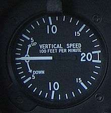
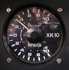
A variometer – also known as a rate of climb and descent indicator (RCDI), rate-of-climb indicator, vertical speed indicator (VSI), or vertical velocity indicator (VVI) – is one of the flight instruments in an aircraft used to inform the pilot of the rate of descent or climb.[1] It can be calibrated in feet per minute, knots (1 kn ≈ 100 ft/min) or metres per second (1 m/s ≈ 200 ft/min), depending on country and type of aircraft.
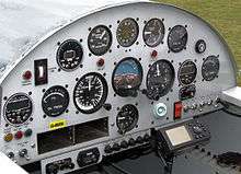
In powered flight the pilot makes frequent use of the VSI to ascertain that level flight is being maintained, especially during turning maneuvers. In gliding, the instrument is used almost continuously during normal flight, often with an audible output, to inform the pilot of rising or sinking air. It is usual for gliders to be equipped with more than one type of variometer. The simpler type does not need an external source of power and can therefore be relied upon to function regardless of whether a battery or power source has been fitted. The electronic type with audio needs a power source to be operative during the flight. The instrument is of little interest during launching and landing, with the exception of aerotow, where the pilot will usually want to avoid releasing in sink.
Description
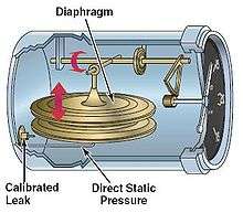
Variometers measure the rate of change of altitude by detecting the change in air pressure (static pressure) as altitude changes. A simple variometer can be constructed by adding a large reservoir (a thermos bottle) to augment the storage capacity of a common aircraft rate-of-climb instrument. In its simplest electronic form, the instrument consists of an air bottle connected to the external atmosphere through a sensitive air flow meter. As the aircraft changes altitude, the atmospheric pressure outside the aircraft changes and air flows into or out of the air bottle to equalise the pressure inside the bottle and outside the aircraft. The rate and direction of flowing air is measured by the cooling of one of two self-heating thermistors and the difference between the thermistor resistances will cause a voltage difference; this is amplified and displayed to the pilot. The faster the aircraft is ascending (or descending), the faster the air flows. Air flowing out of the bottle indicates that the altitude of the aircraft is increasing. Air flowing into the bottle indicates that the aircraft is descending.
Newer variometer designs directly measure the static pressure of the atmosphere using a pressure sensor and detect changes in altitude directly from the change in air pressure instead of by measuring air flow. These designs tend to be smaller as they do not need the air bottle. They are more reliable as there is no bottle to be affected by changes in temperature and less chances for leaks to occur in the connecting tubes.
The designs described above, which measure the rate of change of altitude by automatically detecting the change in static pressure as the aircraft changes altitude are referred to as "uncompensated" variometers. The term "vertical speed indicator" or "VSI" is most often used for the instrument when it is installed in a powered aircraft. The term "variometer" is most often used when the instrument is installed in a glider or sailplane.
An "Inertial-lead" or "Instantaneous" VSI (IVSI) uses accelerometers to provide a quicker response to changes in vertical speed.[2]
Purpose
Human beings, unlike birds and other flying animals, are not able directly to sense climb and sink rates. Before the invention of the variometer, sailplane pilots found it very hard to soar. Although they could readily detect abrupt changes in vertical speed ("in the seat of the pants"), their senses did not allow them to distinguish lift from sink, or strong lift from weak lift. The actual climb/sink rate could not even be guessed at, unless there was some clear fixed visual reference nearby. Being near a fixed reference means being near to a hillside, or to the ground. Except when hill-soaring (exploiting the lift close to the up-wind side of a hill), these are generally very unprofitable positions for glider pilots to be in. The most useful forms of lift (thermal and wave lift) are found at higher altitudes and it is very hard for a pilot to detect or exploit them without the use of a variometer. After the variometer was invented in 1929 by Alexander Lippisch and Robert Kronfeld,[3] the sport of gliding moved into a new realm.
Variometers also became important in foot-launch hang gliding, where the open-to-air pilot hears the wind but needs the variometer to help him or her to detect regions of rising or sinking air. In early hang gliding, variometers were not needed for the short flights or flights close to ridge lift. But the variometer became key as pilots began making longer flights. The first portable variometer for use in hang gliders was the Colver Variometer by Colver Soaring Instruments [4] which served to extend the sport into cross-country thermal flying.[5][6]
Total energy compensation
As the sport of gliding developed, however, it was found that these very simple "uncompensated" instruments had their limitations. The information that glider pilots really need to soar is the total change in energy experienced by the glider, including both altitude and speed. An uncompensated variometer will simply indicate vertical speed of the glider, giving rise to the possibility of a "stick thermal," i.e., a change in altitude caused by stick input only. If a pilot pulls back on the stick, the glider will rise, but also slow down as well. But if a glider is rising without the speed changing, this is an indication of real lift, not "stick lift."
Compensated variometers also include information about the speed of the aircraft, so the total energy (potential and kinetic) is used, not just the change in altitude. For example, if a pilot pushes forward on the stick, speeding up as the plane dives, an uncompensated variometer only indicates that altitude is being lost. But the pilot could pull back on the stick, trading the extra speed for altitude again. A compensated variometer uses both speed and altitude to indicate the change in total energy. So the pilot that pushes the stick forward, diving to gain speed, and then pulls back again to regain altitude will notice no change in total energy on a compensated variometer (neglecting energy loss due to drag).
Most modern sailplanes are equipped with Total Energy compensated variometers.
Total energy compensation in theory
The total energy of the aircraft is:
1.

where is the potential energy, and is the kinetic energy. So the change in total energy is:


2.

Since
3. Potential Energy is proportional to Height

where m is the glider mass and g the acceleration of gravity
and
4. Kinetic Energy is proportional to Velocity squared,

then from 2:
5.

6. Typically, this is converted to an effective altitude change by dividing by the acceleration of gravity, and the mass of the aircraft, so:

Total energy compensation in practice
In most sailplanes, total energy compensation is achieved by connecting the variometer to the atmosphere via a "total energy probe", that produces vacuum proportional to the square of the glider's air speed—in effect, a negative pitot. Alternatively, the subtraction may be done electronically by the flight computer based on indicated airspeed (pitot).
Very few powered aircraft have total energy variometers. The pilot of a powered aircraft is more interested in the true rate of change of altitude, as he often wants to hold a constant altitude or maintain a steady climb or descent.
The total energy probe used to be shaped as a classical venturi (two small funnels connected back-to-back by their narrow ends), or nowadays the Irving Tube—a slot or pair of holes on the back side of a quarter inch vertical tube. The geometry of the total energy probe is such that air flow generates suction (reduced pressure).
To maximise the precision of this compensation effect, the total energy probe needs to be in undisturbed airflow ahead of the aircraft nose or tail fin (the "Braunschweig tube",[7] the long cantilevered tube with a kink in the end that can be seen projecting from the leading edge of the tail fin on most modern sailplanes.)
Netto variometer
A second type of compensated variometer is the Netto or airmass variometer. In addition to TE compensation, the Netto variometer adjusts for the intrinsic sink rate of the glider at a given speed (the polar curve) adjusted for the wing loading due to water ballast. The Netto variometer will always read zero in still air. This provides the pilot with the accurate measurement of air mass vertical movement critical for final glides (the last glide to the ultimate destination location).
The Relative Netto Variometer indicates the vertical speed the glider would achieve IF it flies at thermalling speed - independent of current air speed and attitude. This reading is calculated as the Netto reading minus the glider's minimum sink.
When the glider circles to thermal, the pilot needs to know the glider's vertical speed instead of that of the air mass. The Relative Netto Variometer (or sometimes the super Netto) includes a g-sensor to detect thermalling.
When thermalling, the sensor will detect acceleration (gravity plus centrifugal) above 1 g and tell the relative netto variometer to stop subtracting the sailplane's wing load-adjusted polar sink rate for the duration. Some earlier nettos used a manual switch instead of the g sensor.
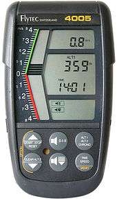
Electronic variometers
In modern gliders, most electronic variometers generate a sound whose pitch and rhythm depends on the instrument reading. Typically the audio tone increases in frequency as the variometer shows a higher rate of climb and decreases in frequency towards a deep groan as the variometer shows a faster rate of descent. When the variometer is showing a climb, the tone is often chopped and the rate of chopping may be increased as the climb rate increases, while during a descent the tone is not chopped. The vario is typically silent in still air or in lift which is weaker than the typical sink rate of the glider at minimum sink. This audio signal allows the pilot to concentrate on the external view instead of having to watch the instruments, thus improving safety and also giving the pilot more opportunity to search for promising looking clouds and other signs of lift. A variometer that produces this type of audible tone is known as an "audio variometer".
Advanced electronic variometers in gliders can present other information to the pilot from GPS receivers. The display can thus show the bearing, distance and height required to reach an objective. In cruise mode (used in straight flight), the vario can also give an audible indication of the correct speed to fly depending on whether the air is rising or sinking. The pilot merely has to input the estimated MacCready setting, which is the expected rate of climb in the next acceptable thermal.
There is an increasing trend for advanced variometers in gliders towards flight computers (with variometer indications) which can also present information such as controlled airspace, lists of turnpoints and even collision warnings. Some will also store positional GPS data during the flight for later analysis.
Radio controlled soaring
Variometers are also used in radio controlled gliders. Typically it takes the form of a radio transmitter in the model, and a receiver held by the pilot on the ground. Depending on the design, the receiver may give the pilot the current altitude of the model (an altimeter) and some sort of display that indicates if the plane is gaining or losing altitude—often via a tone just like in full scale gliders. Other forms of telemetry may also be provided by the system, displaying parameters such as airspeed and battery voltage. Varios used in radio controlled planes may or may not feature total energy compensation (the better/more expensive ones generally do.)
Variometers are strictly optional for R/C glider use—a skilled pilot can generally determine if their plane is going up or down via visual cues alone, and so the use of a variometer is often seen as a `crutch', as a replacement for skill, and many pilots prefer not to use them at all, as the tone can be distracting, and the (usually small) amount of weight added to the plane does affect performance. The use of variometers is prohibited in R/C soaring contests while permitted in others.
Perhaps the most popular brands of R/C variometers are the Picolario and the Pitlab SkyAssistant.
See also
References
- ↑ Federal Aviation Administration, Glider Flying Handbook, Skyhorse Publishing Inc., 2007 ISBN 1-60239-061-4 pages 4-7 and 4-8
- ↑ Federal Aviation Administration (2012). Instrument Flying Handbook (PDF). Washington, DC. p. 5-8. Retrieved 2016-07-12.
- ↑ Michael H. Bednarek (2003). "Dreams of flight". Dreams of flight. Retrieved 2009-05-25.
- ↑ Colver Soaring Instruments in British Hang Gliding History
- ↑ Frank Colver, Colver Variometer
- ↑ The Origin and History of Colver and Roberts Variometers
- ↑ Nicks, Oran, A Simple Total Energy Sensor, NASA TM X-73928, March 1976
Bibliography
| Wikimedia Commons has media related to Variometers. |