Pyranometer

A pyranometer is a type of actinometer used for measuring solar irradiance on a planar surface and it is designed to measure the solar radiation flux density (W/m2) from the hemisphere above within a wavelength range 0.3 μm to 3 μm. The name pyranometer stems from the Greek words πῦρ (pyr), meaning "fire", and ἄνω (ano), meaning "above, sky".
A typical pyranometer does not require any power to operate.
Explanation
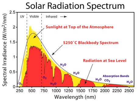
The solar radiation spectrum that reach earth surface extends its wavelenght approximately from 300 to 2,800 nm. Depending on the type of pyranometer used, irradiance measurements with different degrees of spectral sensitivity will be obtained.
To make a measurement of irradiance, it is required by definition that the response to “beam” radiation varies with the cosine of the angle of incidence. This ensures a full response when the solar radiation hits the sensor perpendicularly (normal to the surface, sun at zenith, 0° angle of incidence), zero response when the sun is at the horizon (90° angle of incidence, 90° zenith angle), and 0.5 at a 60° angle of incidence. It follows that a pyranometer should have a so-called “directional response” or “cosine response” close to the ideal cosine characteristic.
Classification of pyranometers

Following the classifications and definitions noted in the ISO 9060,[1] three types of pyranometers can be recognized and grouped in two different technologies: thermopile technology and silicon semiconductor technology.
The light sensitivity, known as 'spectral response', depends on the type of pyranometer. The figure to the right shows the spectral responses of the three types of pyranometer in relation to the Solar Radiation Spectrum. The Solar Radiation Spectrum represents the spectrum of sunlight that reaches the Earth’s surface at sea level, at midday with A.M. (air mass) = 1.5.
The latitude and altitude influence this spectrum. The spectrum is influenced also by aerosol and pollution.
Thermopile pyranometers
A thermopile pyranometer is a sensor based on thermopiles designed to measure the broadband of the solar radiation flux density from a 180° field of view angle. A thermopile pyranometer thus usually measures 300 to 2800 nm with a largely flat spectral sensitivity (see the Spectral Response graph) The first generation of thermopile pyranometers had the active part of the sensor equally divided in black and white sectors. Irradiation was calculated from the differential measure between the temperature of the black sectors, exposed to the sun, and the temperature of the white sectors, sectors not exposed to the sun or better said in the shades.
In all thermopile technology, irradiation is proportional to the difference between the temperature of the sun exposed area and the temperature of the shadow area.
Design
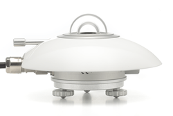
In order to attain the proper directional and spectral characteristics, a thermopile pyranometer is constructed with the following main components:

- A thermopile sensor[2] with a black coating. It absorbs all solar radiation, has a flat spectrum covering the 300 to 50,000 nanometer range, and has a near-perfect cosine response.
- A glass dome. It limits the spectral response from 300 to 2,800 nanometers (cutting off the part above 2,800 nm), while preserving the 180° field of view. It also shields the thermopile sensor from convection.
In the modern thermopile pyranometers the active (hot) junctions of the thermopile are located beneath the black coating surface and are heated by the radiation absorbed from the black coating.[3] The passive (cold) junctions of the thermopile are fully protected from solar radiation and in thermal contact with the pyranometer housing, which serves as a heat-sink. This prevents any alteration from yellowing or decay when measuring the temperature in the shade, thus impairing the measure of the solar irradiance.
The thermopile generates a small voltage in proportion to the temperature difference between the black coating surface and the instrument housing. This is of the order of 10 µ • VW/m2. Typically, on a sunny day the output is around 10 mV. Each pyranometer has a unique sensitivity, unless otherwise equipped with a board for signal calibration.
Usage
Thermopile pyranometers are frequently used in meteorology, climatology, climate change research, building engineering physics and in photovoltaic systems. They are usually installed horizontally in meteorological stations; when they are mounted beside solar panels, they are typically mounted with the sensor surface on the plane of the panel.
Photodiode-based pyranometer
Also known as a silicon pyranometer in the ISO 9060,[4] a photodiode-based pyranometer can detect the portion of the solar spectrum between 400 nm and 900 nm, with the most performant detecting between 350 nm and 1100 nm. The photodiode converts the aforementioned solar spectrum frequencies into current at high speed, thanks to the photoelectric effect. The conversion is influenced by the temperature with a raise in current produced by the raise in temperature (about 0,1% • °C)
Design
A photodiode-based pyranometer is composed by a housing dome, a photodiode, and a diffuser or optical filters. The photodiode has a small surface area and acts as a sensor. The current generated by the photodiode is proportional to irradiance; an output circuit, such as a transimpedance amplifier, generates a voltage directly proportional to the photocurrent. The output is usually on the order of millivolts, the same order of magnitude of thermopile-type pyranometers.
Usage
Photodiode-based pyranometers are implemented where the quantity of irradiation of the visible solar spectrum, or of certain portions such as UV, PAR, or IR, needs to be calculated. This is done by using diodes with specific spectral responses. Photodiode-based pyranometers are the core of luxmeter used in photography, cinema and lighting technique. Sometimes they are also installed close to modules of photovoltaic systems.
Photovoltaic pyranometer
Built around the 2000s concurrently with the spread of photovoltaic systems, the photovoltaic pyranometer is a derivation of the photodiode pyranometer. It answered the need for a single reference photovoltaic cell when measuring the power of cell and photovoltaic modules.[5] Specifically, each cell and module is tested through flash tests by their respective manufacturers, and thermopile pyranometers do not possess the adequate speed of response nor the same spectral response of a cell. This would create obvious mismatch when measuring power, which would need to be quantified.[6][7] In the technical documents, this pyranometer is also known as "reference PV cell", "irradiance sensor", "solarimeter", "solar sensor", as bibliographies are more recent than the ISO 9060.
The active part of the sensor is composed of a photovoltaic cell working in near short-circuit condition. As such, the generated current is directly proportionate to the solar radiation hitting the cell in a range between 350 nm and 1150 nm. When invested by a luminous radiation in the mentioned range, it produces current as a consequence of the photovoltaic effect. Its sensitivity is not flat, but it is same as that of Silicon photovoltaic cell. See the Spectral Response graph.
Design
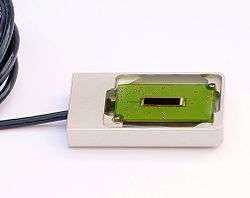
A photovoltaic pyranometer is essentially assembled with the following parts:
- A metallic container with a fixing staff
- A small photovoltaic cell
- Signal conditioning electronics
Silicon sensors such as the photodiode and the photovoltaic cell vary the output in function of temperature. In the more recent models, the electronics compensate the signal with the temperature, therefore removing the influence of temperature out of the values of solar irradiance. Inside several models, the case houses a board for the amplification and conditioning of the signal.
Usage
Photovoltaic pyranometers are used in solar simulators and alongside photovoltaic system for the calculation of photovoltaic modules effective power and system performances. Thanks to its spectral response, obviously similar to that of a photovoltaic module, it is used also in preliminary diagnosis of malfunction in photovoltaic systems.
Signal conditioning
The natural output value of these pyranometers do not usually exceed tens of millivolt(mV). It is considered a ‘weak’ signal, and as such, rather vulnerable to electromagnetic interferences, especially where the cable runs across decametrical distances or lies in photovoltaic systems. Thus, these sensors are frequently equipped with signal conditioning electronics, which allows them to amplify its natural output value by 100 or 1000 times.
Another solution implies greater immunities to noises, like a current loop or RS-485 output, suitable for ambiances with electromagnetic interferences typical of medium-large scale photovoltaic systems. The equipped electronics often concur to normalize the signal output into a predetermined value.
Standardization and calibration
Both thermopile-type and photovoltaic pyranometers are manufactured according to standards.
Thermopile Pyranometers follow the ISO 9060 standard, which is also adopted by the World Meteorological Organization (WMO). This standard discriminates three classes. Rather confusingly, the best is confusingly called "secondary standard" (i.e., calibrated by direct comparison with the single primary instrument). The second best is defined as "first class" and the last one "second class.".[8]
Photovoltaic pyranometers are standardized under IEC60904-4, its metrological traceability.
For thermopile pyranometers, the calibration is typically done having the World Radiometric Reference (WRR) as absolute reference. This is maintained by PMOD in Davos, Switzerland.[9] In addition to the World Radiometric Reference there are private laboratories such as such as ISO-Cal North Americawho have acquired accreditation for these unique calibration. For the "secondary standard" pyranometer, calibration is done following ASTM G167, or ISO 9846.[10] First and second class pyranometers are usually calibrated according to ASTM E824, and ISO 9847.
Photovoltaic pyranometers are calibrated under IEC 60904-4 for primary reference samples and under IEC 60904-2 for secondary reference samples and the instruments intended for sale.
In both standards, their respective traceability chain starts with the primary standard known as the Group of Cavity Radiometer by the World Radiometric Reference (WRR).[11]
See also
- Actinometer
- Photodiode
- Heat flux sensor
- Net radiometer
- Pyrgeometer
- Pyrheliometer
- Radiometer
- Sunlight
- Solar constant
- Sun path
References
- ↑ ISO9060 :1990 Classification of Pyranometers
- ↑ "greenTEG Application Note Solar Radiation".
- ↑ http://www.kippzonen.com/News/572/The-Working-Principle-of-a-Thermopile-Pyranometer#
- ↑ ISO9060 - Paragraph 3.4 (1990)
- ↑ IEC 60904-4:Procedures for establishing calibration traceability
- ↑ EN 60904-2: Requirements for reference solar devices
- ↑ EN 60904-7: Computation of spectral mismatch correction
- ↑ "ISO 9060:1990 Classification of Pyranometers".
- ↑ "World Radiometric Reference".
- ↑ ISO 9846:1993 -Calibration of a Pyranometer Using a Pyrheliometer
- ↑ IEC 60904-4:Procedures for establishing calibration traceability- Table1 and Fig.1
External links
| Wikimedia Commons has media related to Pyranometer. |