Beam engine

A beam engine is a type of steam engine where a pivoted overhead beam is used to apply the force from a vertical piston to a vertical connecting rod. This configuration, with the engine directly driving a pump, was first used by Thomas Newcomen around 1705 to remove water from mines in Cornwall. The efficiency of the engines was improved by engineers including James Watt who added a separate condenser, Jonathan Hornblower and Arthur Woolf who compounded the cylinders, and William McNaught (Glasgow) who devised a method of compounding an existing engine. Beam engines were first used to pump water out of mines or into canals, but could be used to pump water to supplement the flow for a waterwheel powering a mill.

The rotative beam engine is a later design of beam engine where the connecting rod drives a flywheel, by means of a crank (or, historically, by means of a sun and planet gear). These beam engines could be used to directly power the line-shafting in a mill. They also could be used to power steam ships.
History
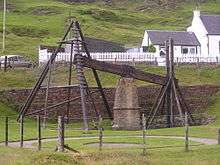
The first beam engines were water-powered, and used to pump water from mines. A preserved example may be seen at Wanlockhead in Scotland.
Beam engines were extensively used to power pumps on the English canal system when it was expanded by means of locks early in the Industrial Revolution, and also to drain water from mines in the same period, and as winding engines.
The first steam-related beam engine was developed by Thomas Newcomen. This was not, strictly speaking, steam powered, as the steam introduced below the piston was condensed to create a partial vacuum thus allowing atmospheric pressure to push down the piston. It was therefore called an Atmospheric Engine. The Newcomen atmospheric engine was adopted by many mines in Cornwall and elsewhere, but it was relatively inefficient and consumed a large quantity of fuel. The engine was improved by John Smeaton but James Watt resolved the main inefficiencies of the Newcomen engine in his Watt steam engine by the addition of a separate condenser, thus allowing the cylinder to remain hot. Technically this was still an atmospheric engine until (under subsequent patents) he enclosed the upper part of the cylinder, introducing steam to also push the piston down. This made it a true steam engine and arguably confirms him as the inventor of the steam engine. He also patented the centrifugal governor and the parallel motion. the latter allowed the replacement of chains round an arch head and thus allowed its use as a rotative engine.
His patents remained in place until the start of the 19th Century and some say that this held back development. However, in reality development had been ongoing by others and at the end of the patent period there was an explosion of new ideas and improvements. Watt's beam engines were used commercially in much larger numbers and many continued to run for 100 years or more.
Watt held patents on key aspects of his engine's design, but his rotative engine was equally restricted by the patent by an other of the simple crank. The beam engine went on to be considerably improved and enlarged in the tin- and copper-rich areas of south west England, which enabled the draining of the deep mines that existed there. Consequently, the Cornish beam engines became world-famous, as they remain among the most massive beam engines ever constructed.
Rotative beam engines

In a rotative beam engine, the piston is mounted vertically, and the piston rod drives the beam as before. A connecting rod from the other end of the beam, rather than driving a pump rod, now drives a flywheel.
Early Watt engines used Watt's patent sun and planet gear, rather than a simple crank, as use of the latter was protected by a patent owned by James Pickard. Once the patent had expired, the simple crank was employed universally.
Marine beam engines
The first steam-powered ships used variants of the rotative beam engine. These marine steam engines – known as side-lever, grasshopper, crosshead, or 'walking beam', among others – all varied from the original land-based machines by locating the beam or beams in different positions to take up less room on board ship.
![]() Media related to Rotative beam engines at Wikimedia Commons
Media related to Rotative beam engines at Wikimedia Commons
Compounding
Compounding involves two or more cylinders; low-pressure steam from the first, high-pressure, cylinder is passed to the second cylinder where it expands further and provides more drive. This is the compound effect; the waste steam from this can produce further work if it is then passed into a condenser in the normal way. The first experiment with compounding was conducted by Jonathan Hornblower, who took out a patent in 1781. His first engine was installed at Tincroft Mine, Cornwall. It had two cylinders – one 21-inch (0.53 m) diameter with 6-foot (1.8 m) stroke and one 27-inch (0.69 m) diameter with 8-foot (2.4 m) stroke – placed alongside each other at one end of the beam. The early engines showed little performance gain: the steam pressure was too low, interconnecting pipes were of small diameter and the condenser ineffective.[1]
At this time the laws of thermodynamics were not adequately understood, particularly the concept of absolute zero. Engineers such as Arthur Woolf were trying to tackle an engineering problem with an imperfect understanding of the physics. In particular, their valve gear was cutting-in at the wrong position in the stroke, not allowing for expansive working in the cylinder. Successful Woolf compound engines were produced in 1814, for the Wheal Abraham copper mine and the Wheal Vor tin mine.[2]
McNaught engines
William McNaught patented a compound beam engine in 1845. On a beam engine of the standard Boulton & Watt design he placed a high-pressure cylinder, on the opposite side of the beam to the existing single cylinder, where the water pump was normally fitted. This had two important effects: it massively reduced the pressure on the beam, and the connecting steam pipe, being long, acted as an expansive receiver – the element missing in the Woolf design.[3] This modification could be made retrospectively, and engines so modified were said to be "McNaughted". The advantages of a compound engine were not significant at pressures under 60psi, but showed at over 100psi.
Preserved beam engines

- Abbey Pumping Station (Leicester, England) - houses four Woolf compound rotative beam engines built by Gimson and Company, Leicester[4]
- Bolton Steam Museum (Bolton, England) – includes several rotative beam engines originally used to drive mills
- Claymills Pumping Station (Burton-on-Trent, Staffordshire, England) - four Woolf compound, rotative, beam pumping engines; five Lancashire boilers; over thirty auxiliary engines on the site, including the oldest working steam driven dynamo in the country.
- Coldharbour Mill (Uffculme, Devon) - 1867 Kittoe and Brotherhood beam engine plus Pollit & Wigzell 300hp cross compound engine. In steam most Bank Holidays driving the rope race, together with other smaller machines.
- Strumpshaw Steam Museum (Strumpshaw, England) - Features a now Compressed Air powered former beam engine from Addington.
- Coultershaw Beam Pump (West Sussex, England) – preserved water-powered beam engine from 1782
- Crofton Pumping Station (Great Bedwyn, England) – two engines, including the oldest working 'Cornish' engine, in its original location, in the world (1812)
- Crossness Pumping Station (Abbey Wood, London, England) – set of four rotative beam engines: the largest surviving working examples
- Museum De Cruquius (Cruquius, The Netherlands) – the eight-beamed engine at Cruquius is thought to be the largest steam engine ever built
- Newcomen Memorial Engine (Dartmouth, Devon) - dating from about 1725. Hydraulic mechanism added for demonstration purposes.
- Dogdyke Engine (Tattershall, Lincolnshire) – drainage engine and scoop wheel, steamed summer weekends.
- Eastney Beam Engine House (Portsmouth, England) – contains two rotative beam engines for sewage-pumping, dating from 1887.
- Elsecar (Elsecar, South Yorkshire, England) – the only surviving Newcomen engine (in the world) to have remained in its original location (1795)
- The Henry Ford Museum (Dearborn, Michigan, US) - Fairbottom Bobs, a Newcomen engine of the 1760s
- The London Museum of Water & Steam (Brentford, London, England) – five 'Cornish' engines (in original location) of which four are operational, together with two operational rotative beam engines (in museum), including the largest working 'Cornish' engine in the world with a 90" Cylinder
- Grazebrook beam engine- A large pumping Boulton & Watt designed with a 42 inches (1.1 m) bore on static display on the Dartmouth roundabout on the A38(M) in Birmingham, England
- Levant Mine and Beam Engine (Trewellard, Pendeen, England) – a working beam engine on a National Trust property in West Cornwall, England
- Markfield Beam Engine (Tottenham, London, England) – a compound, rotative engine
- Nottingham Industrial Museum (Nottingham, England) - The Steam Gallery contains an impressive Basford Beam Engine, one of a pair of engines built in 1858 by R. W. Hawthorn in Newcastle upon Tyne. It was installed at Basford Pumping Station to lift water 110 ft from the sandstone below to supply fresh water to the City of Nottingham. The engine was replaced in 1965 and was removed to the purpose-built Steam Gallery where it was first fired in 1975
- Pinchbeck Engine (Spalding, Lincolnshire) – statically preserved 'A'-frame engine.
- Ryhope Engines Museum (Ryhope, England) – twin rotative beam engines; built 1868
- Smethwick Engine (Smethwick, Birmingham, England) – oldest working steam engine in the world (1779)
- Stretham Old Engine (Stretham, Cambridgeshire) – Statically preserved engine and scoop wheel.
- The Western Springs Water Works (Auckland, New Zealand) – 1877 double Woolf compound engine. In original location, restored in working order with Transport and Technology Museum built around it. The restoration of the Pumphouse and original Engineers cottage was awarded with the 2009 Award of Merit from UNESCO's Asia-Pacific Heritage Awards for Culture Heritage Conservation programme.
- The Caprington Colliery Newcomen engine at the National Museum of Scotland. Occasional working on pneumatics
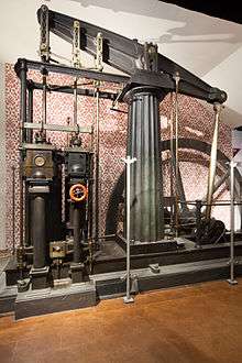
- The Boulton and Watt rotative beam engine (sun and planet type) at the National Museum of Scotland (1786).[5][6] Occasional working by pneumatics
- Poldark Mine (Trenear, Cornwall) - Harvey of Hale Cornish Beam Engine from Bunny Tin Mine and later Greensplat China Clay Pit dating from about 1850. Hydraulic mechanism added for demonstration purposes. Last to have worked commercially in Cornwall to December 1959, moved to Poldark in 1972[7]
See also
- Cataract (beam engine)
- Cornish engine
- Gimson and Company
- Man engine
- Marine steam engine
- Mining in Cornwall
- Prestongrange Industrial Heritage Museum
- Pumpjack
- Six-column beam engine
- Stationary engine
References
- ↑ Hills 1989, p. 147
- ↑ Hills 1989, p. 153
- ↑ Hills 1989, p. 157
- ↑ http://www.abbeypumpingstation.org
- ↑ http://www.gracesguide.co.uk/Boulton_and_Watt Graces Guide
- ↑ http://www.doorsopendays.org.uk/opendays/newsArticle.aspx?newsid=132
- ↑ The Making of Wendron B A Fyfield-Shayler 1979
Bibliography
- Hills, Richard Leslie (1989). Power from Steam: A History of the Stationary Steam Engine. Cambridge University Press. p. 244. ISBN 0-521-45834-X. Retrieved January 2009. Check date values in:
|access-date=(help) - Crowley, T.E. (1982). The Beam Engine. Senecio Publishing. ISBN 0-906831-02-4.
External links
| Wikimedia Commons has media related to Beam engines. |
- Animation of a Watt beam engine.
- The oldest surviving mine engine in Cornwall.
- Archive footage of the engines at Addington Pumping Station in July 1973, a year prior to decommissioning.