USB
 Certified USB logo | |||
| Type | Bus | ||
|---|---|---|---|
| Production history | |||
| Designer | Compaq, DEC, IBM, Intel, Microsoft, NEC and Nortel | ||
| Designed | January 1996 | ||
| Produced | Since May 1996[1] | ||
| Superseded | Serial port, parallel port, game port, Apple Desktop Bus, PS/2 port, and MagSafe | ||
| General specifications | |||
| Length | 2–5 m (6 ft 7 in–16 ft 5 in) (by category) | ||
| Width |
| ||
| Height |
| ||
| Hot pluggable | Yes | ||
| External | Yes | ||
| Cable |
| ||
| Pins |
| ||
| Connector | Unique | ||
| Electrical | |||
| Signal | 5 V DC | ||
| Max. voltage |
| ||
| Max. current |
| ||
| Data | |||
| Data signal | Packet data, defined by specifications | ||
| Width | 1 bit | ||
| Bitrate | 1.5, 12, 480, 5,000, 10,000 Mbit/s (depending on mode) | ||
| Max. devices | 127 | ||
| Protocol | Serial | ||
| Pin out | |||
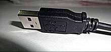
 | |||
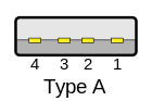
| The type-A plug (left) and type-B plug (right) | |||
| Pin 1 | VBUS (+5 V) | ||
| Pin 2 | Data− | ||
| Pin 3 | Data+ | ||
| Pin 4 | Ground | ||
USB, short for Universal Serial Bus, is an industry standard initially developed in the mid-1990s that defines the cables, connectors and communications protocols used in a bus for connection, communication, and power supply between computers and electronic devices.[4] It is currently developed by the USB Implementers Forum (USB IF).
USB was designed to standardize the connection of computer peripherals (including keyboards, pointing devices, digital cameras, printers, portable media players, disk drives and network adapters) to personal computers, both to communicate and to supply electric power. It has become commonplace on other devices, such as smartphones, PDAs and video game consoles.[5] USB has effectively replaced a variety of earlier interfaces, such as parallel ports, as well as separate power chargers for portable devices.
Overview
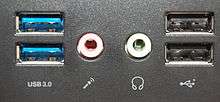
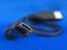
In general, there are three basic formats of USB connectors: the default or standard format intended for desktop or portable equipment (for example, on USB flash drives), the mini intended for mobile equipment (now deprecated except the Mini-B, which is used on many cameras), and the thinner micro size, for low-profile mobile equipment (most modern mobile phones). Also, there are 5 modes of USB data transfer, in order of increasing bandwidth: Low Speed (from 1.0), Full Speed (from 1.0), High Speed (from 2.0), SuperSpeed (from 3.0), and SuperSpeed+ (from 3.1); modes have differing hardware and cabling requirements. USB devices have some choice of implemented modes, and USB version is not a reliable statement of implemented modes. Modes are identified by their names and icons, and the specifications suggests that plugs and receptacles be colour-coded (SuperSpeed is identified by blue).
Unlike other data buses (e.g., Ethernet, HDMI), USB connections are directed, with both upstream and downstream ports emanating from a single host. This applies to electrical power, with only downstream facing ports providing power; this topology was chosen to easily prevent electrical overloads and damaged equipment. Thus, USB cables have different ends: A and B, with different physical connectors for each. Therefore, in general, each different format requires four different connectors: a plug and receptacle for each of the A and B ends. USB cables have the plugs, and the corresponding receptacles are on the computers or electronic devices. In common practice, the A end is usually the standard format, and the B side varies over standard, mini, and micro. The mini and micro formats also provide for USB On-The-Go with a hermaphroditic AB receptacle, which accepts either an A or a B plug. On-the-Go allows USB between peers without discarding the directed topology by choosing the host at connection time; it also allows one receptacle to perform double duty in space-constrained applications.
There are cables with A plugs on both ends, which may be valid if the cable includes, for example, a USB host-to-host transfer device with 2 ports, but they could also be non-standard and erroneous and should be used carefully.[6]
The micro format is the most durable from the point of designed insertion lifetime. The standard and mini connectors have a design lifetime of 1,500 insertion-removal cycles,[7] the improved Mini-B connectors increased this to 5,000. The micro connectors were designed with frequent charging of portable devices in mind, so have a design life of 10,000 cycles[7] and also place the flexible contacts, which wear out sooner, on the easily replaced cable, while the more durable rigid contacts are located in the receptacles. Likewise, the springy component of the retention mechanism, parts that provide required gripping force, were also moved into plugs on the cable side.[8]
History
A group of seven companies began the development of USB in 1994: Compaq, DEC, IBM, Intel, Microsoft, NEC, and Nortel.[10] The goal was to make it fundamentally easier to connect external devices to PCs by replacing the multitude of connectors at the back of PCs, addressing the usability issues of existing interfaces, and simplifying software configuration of all devices connected to USB, as well as permitting greater data rates for external devices. A team including Ajay Bhatt worked on the standard at Intel;[11][12] the first integrated circuits supporting USB were produced by Intel in 1995.[13]
The original USB 1.0 specification, which was introduced in January 1996, defined data transfer rates of 1.5 Mbit/s Low Speed and 12 Mbit/s Full Speed.[13] Microsoft Windows 95, OSR 2.1 provided OEM support for the devices. The first widely used version of USB was 1.1, which was released in September 1998. The 12 Mbit/s data rate was intended for higher-speed devices such as disk drives, and the lower 1.5 Mbit/s rate for low data rate devices such as joysticks.[14] Apple Inc.'s iMac was the first mainstream product with USB and the iMac's success popularized USB itself.[15] Following Apple's design decision to remove all legacy ports from the iMac, many PC manufacturers began building legacy-free PCs, which led to the broader PC market using USB as a standard.[16][17][18]
The USB 2.0 specification was released in April 2000 and was ratified by the USB Implementers Forum (USB-IF) at the end of 2001. Hewlett-Packard, Intel, Lucent Technologies (now Alcatel-Lucent), NEC, and Philips jointly led the initiative to develop a higher data transfer rate, with the resulting specification achieving 480 Mbit/s, a 40-times increase over the original USB 1.1 specification.
The USB 3.0 specification was published on 12 November 2008. Its main goals were to increase the data transfer rate (up to 5 Gbit/s), decrease power consumption, increase power output, and be backward compatible with USB 2.0.[19] USB 3.0 includes a new, higher speed bus called SuperSpeed in parallel with the USB 2.0 bus.[20] For this reason, the new version is also called SuperSpeed.[21] The first USB 3.0 equipped devices were presented in January 2010.[21][22]
As of 2008, approximately 6 billion USB ports and interfaces were in the global marketplace, and about 2 billion were being sold each year.[23]
In December 2014, USB-IF submitted USB 3.1, USB Power Delivery 2.0 and USB Type-C specifications to the IEC (TC 100 – Audio, video and multimedia systems and equipment) for inclusion in the international standard IEC 62680 Universal Serial Bus interfaces for data and power, which is currently based on USB 2.0.[24]
Version history
Overview
| Release name | Release date | Maximum transfer rate | Note |
|---|---|---|---|
| USB 0.8 | December 1994 | Prerelease | |
| USB 0.9 | April 1995 | Prerelease | |
| USB 0.99 | August 1995 | Prerelease | |
| USB 1.0 Release Candidate | November 1995 | Prerelease | |
| USB 1.0 | January 1996 | Low Speed (1.5 Mbit/s), Full Speed (12 Mbit/s) | |
| USB 1.1 | August 1998 | ||
| USB 2.0 | April 2000 | High Speed (480 Mbit/s) | |
| USB 3.0 | November 2008 | SuperSpeed (5 Gbit/s) | Also referred to as USB 3.1 Gen 1 by USB 3.1 standard[25] |
| USB 3.1 | July 2013 | SuperSpeed+ (10 Gbit/s) | Also referred to as USB 3.1 Gen 2 by USB 3.1 standard[25] |
Power related specifications
| Release name | Release date | Max. power | Note |
|---|---|---|---|
| USB Battery Charging 1.0 | 2007-03-08 | 5 V, 1.5 A | |
| USB Battery Charging 1.1 | 2009-04-15 | ||
| USB Battery Charging 1.2 | 2010-12-07 | 5 V, 5 A | |
| USB Power Delivery revision 1.0 (version 1.0) | 2012-07-05 | 20 V, 5 A | Using FSK protocol over bus power (VBUS) |
| USB Power Delivery revision 1.0 (version 1.3) | 2014-03-11 | ||
| USB Type-C 1.0 | 2014-08-11 | 5 V, 3 A | New connector and cable specification |
| USB Power Delivery revision 2.0 (version 1.0) | 2014-08-11 | 20 V, 5 A | Using BMC protocol over communication channel (CC) on type-C cables. |
| USB Type-C 1.1 | 2015-04-03 | 5 V, 3 A | |
| USB Power Delivery revision 2.0 (version 1.1) | 2015-05-07 | 20 V, 5 A | |
| USB Power Delivery revision 2.0 (version 1.2) | 2016-03-25 | 20 V, 5 A |
USB 1.x
Released in January 1996, USB 1.0 specified data rates of 1.5 Mbit/s (Low Bandwidth or Low Speed) and 12 Mbit/s (Full Bandwidth or Full Speed). It did not allow for extension cables or pass-through monitors, due to timing and power limitations. Few USB devices made it to the market until USB 1.1 was released in August 1998, fixing problems identified in 1.0, mostly related to using hubs. USB 1.1 was the earliest revision that was widely adopted and led to Legacy-free PCs.[15][16][17][18]
USB 2.0

USB 2.0 was released in April 2000, adding a higher maximum signaling rate of 480 Mbit/s (High Speed or High Bandwidth), in addition to the USB 1.x Full Speed signaling rate of 12 Mbit/s. Due to bus access constraints, the effective throughput of the High Speed signaling rate is limited to 280 Mbit/s or 35 MB/s.[26]
Further modifications to the USB specification have been made via Engineering Change Notices (ECN). The most important of these ECNs are included into the USB 2.0 specification package available from USB.org:[27]
- Mini-A and Mini-B Connector ECN: Released in October 2000.
Specifications for Mini-A and Mini-B plug and receptacle. Also receptacle that accepts both plugs for On-The-Go. These should not be confused with Micro-B plug and receptacle. - Pull-up/Pull-down Resistors ECN: Released in May 2002
- Interface Associations ECN: Released in May 2003.
New standard descriptor was added that allows associating multiple interfaces with a single device function. - Rounded Chamfer ECN: Released in October 2003.
A recommended, backward compatible change to Mini-B plugs that results in longer lasting connectors. - Unicode ECN: Released in February 2005.
This ECN specifies that strings are encoded using UTF-16LE. USB 2.0 specified Unicode, but did not specify the encoding. - Inter-Chip USB Supplement: Released in March 2006
- On-The-Go Supplement 1.3: Released in December 2006.
USB On-The-Go makes it possible for two USB devices to communicate with each other without requiring a separate USB host. In practice, one of the USB devices acts as a host for the other device. - Battery Charging Specification 1.1: Released in March 2007 and updated on 15 April 2009.
Adds support for dedicated chargers (power supplies with USB connectors), host chargers (USB hosts that can act as chargers) and the No Dead Battery provision, which allows devices to temporarily draw 100 mA current after they have been attached. If a USB device is connected to a dedicated charger, maximum current drawn by the device may be as high as 1.8 A. (Note that this document is not distributed with USB 2.0 specification package, only USB 3.0 and USB On-The-Go.) - Micro-USB Cables and Connectors Specification 1.01: Released in April 2007.
- Link Power Management Addendum ECN: Released in July 2007.
This adds sleep, a new power state between enabled and suspended states. Device in this state is not required to reduce its power consumption. However, switching between enabled and sleep states is much faster than switching between enabled and suspended states, which allows devices to sleep while idle. - Battery Charging Specification 1.2:[28] Released in December 2010.
Several changes and increasing limits including allowing 1.5 A on charging ports for unconfigured devices, allowing High Speed communication while having a current up to 1.5 A and allowing a maximum current of 5 A.
USB 3.0

The USB 3.0 specification was released on 12 November 2008, with its management transferring from USB 3.0 Promoter Group to the USB Implementers Forum (USB-IF), and announced on 17 November 2008 at the SuperSpeed USB Developers Conference.[29]
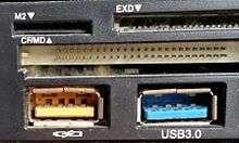
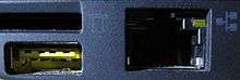
USB 3.0 defines a new SuperSpeed transfer mode, with associated new backwards-compatible plugs, receptacles, and cables. SuperSpeed plugs and receptacles are identified with a distinct logo and blue inserts in standard format receptacles.
The new SuperSpeed mode provides a data signaling rate of 5.0 Gbit/s. However, due to the overhead incurred by 8b/10b encoding, the payload throughput is actually 4 Gbit/s, and the specification considers it reasonable to achieve only around 3.2 Gbit/s (0.4 GB/s or 400 MB/s). However, this should increase with future hardware advances. Communication is full-duplex in SuperSpeed transfer mode; earlier modes are half-duplex, arbitrated by the host.[30]
Low-power and high-power devices remain operational with this standard, but devices using SuperSpeed can take advantage of increased available current of between 150 mA and 900 mA, respectively.[31] Additionally, there is a Battery Charging Specification (Version 1.2 – December 2010), which increases the power handling capability to 1.5 A but does not allow concurrent data transmission.[28] The Battery Charging Specification requires that the physical ports themselves be capable of handling 5 A of current but limits the maximum current drawn to 1.5 A.
USB 3.1
A January 2013 press release from the USB group revealed plans to update USB 3.0 to 10 Gbit/s.[32] The group ended up creating a new USB specification, USB 3.1, which was released on 31 July 2013,[33] replacing the USB 3.0 standard. The USB 3.1 specification takes over the existing USB 3.0's SuperSpeed USB transfer rate, also referred to as USB 3.1 Gen 1, and introduces a faster transfer rate called SuperSpeed USB 10 Gbps, also referred to as USB 3.1 Gen 2,[25] putting it on par with a single first-generation Thunderbolt channel. The new mode's logo features a caption stylized as SUPERSPEED+. The USB 3.1 standard increases the data signaling rate to 10 Gbit/s, double that of SuperSpeed USB, and reduces line encoding overhead to just 3% by changing the encoding scheme to 128b/132b.[34] The first USB 3.1 implementation demonstrated transfer speeds of 7.2 Gbit/s.[35]
The USB 3.1 standard is backward compatible with USB 3.0 and USB 2.0.
USB Type-C

Developed at roughly the same time as the USB 3.1 specification, but distinct from it, the USB Type-C Specification 1.0 was finalized in August 2014[36] and defines a new small reversible-plug connector for USB devices.[37] The Type-C plug connects to both hosts and devices, replacing various Type-A and Type-B connectors and cables with a standard meant to be future-proof, similar to Apple Lightning and Thunderbolt.[36][38] The 24-pin double-sided connector provides four power-ground pairs, two differential pairs for USB 2.0 data bus (though only one pair is implemented in a Type-C cable), four pairs for super-speed data bus, two "sideband use" pins, and two configuration pins for cable orientation detection, dedicated biphase mark code (BMC) configuration data channel, and VCONN +5 V power for active cables.[39][40] Type-A and Type-B adaptors and cables are required for older devices to plug into Type-C hosts. Adapters and cables with a Type-C receptacle are not allowed.[41]
Full-featured USB Type-C cables are active, electronically marked cables that contain a chip with an ID function based on the configuration data channel and vendor-defined messages (VDMs) from the USB Power Delivery 2.0 specification. USB Type-C devices also support power currents of 1.5 A and 3.0 A over the 5 V power bus in addition to baseline 900 mA; devices can either negotiate increased USB current through the configuration line, or they can support the full Power Delivery specification using both BMC-coded configuration line and legacy BFSK-coded VBUS line.
Alternate Mode dedicates some of the physical wires in the Type-C cable for direct device-to-host transmission of alternate data protocols. The four high-speed lanes, two sideband pins, and—
System design
The design architecture of USB is asymmetrical in its topology, consisting of a host, a multitude of downstream USB ports, and multiple peripheral devices connected in a tiered-star topology. Additional USB hubs may be included in the tiers, allowing branching into a tree structure with up to five tier levels. A USB host may implement multiple host controllers and each host controller may provide one or more USB ports. Up to 127 devices, including hub devices if present, may be connected to a single host controller.[42][43] USB devices are linked in series through hubs. One hub—built into the host controller—is the root hub.
A physical USB device may consist of several logical sub-devices that are referred to as device functions. A single device may provide several functions, for example, a webcam (video device function) with a built-in microphone (audio device function). This kind of device is called a composite device. An alternative to this is compound device, in which the host assigns each logical device a distinctive address and all logical devices connect to a built-in hub that connects to the physical USB cable.
.svg.png)
USB device communication is based on pipes (logical channels). A pipe is a connection from the host controller to a logical entity, found on a device, and named an endpoint. Because pipes correspond 1-to-1 to endpoints, the terms are sometimes used interchangeably. A USB device could have up to 32 endpoints (16 IN, 16 OUT), though it's rare to have so many. An endpoint is defined and numbered by the device during initialization (the period after physical connection called "enumeration") and so is relatively permanent, whereas a pipe may be opened and closed.
There are two types of pipe: stream and message. A message pipe is bi-directional and is used for control transfers. Message pipes are typically used for short, simple commands to the device, and a status response, used, for example, by the bus control pipe number 0. A stream pipe is a uni-directional pipe connected to a uni-directional endpoint that transfers data using an isochronous,[44] interrupt, or bulk transfer:
- Isochronous transfers
- At some guaranteed data rate (often, but not necessarily, as fast as possible) but with possible data loss (e.g., realtime audio or video)
- Interrupt transfers
- Devices that need guaranteed quick responses (bounded latency) (e.g., pointing devices and keyboards)
- Bulk transfers
- Large sporadic transfers using all remaining available bandwidth, but with no guarantees on bandwidth or latency (e.g., file transfers)
An endpoint of a pipe is addressable with a tuple (device_address, endpoint_number) as specified in a TOKEN packet that the host sends when it wants to start a data transfer session. If the direction of the data transfer is from the host to the endpoint, an OUT packet (a specialization of a TOKEN packet) having the desired device address and endpoint number is sent by the host. If the direction of the data transfer is from the device to the host, the host sends an IN packet instead. If the destination endpoint is a uni-directional endpoint whose manufacturer's designated direction does not match the TOKEN packet (e.g. the manufacturer's designated direction is IN while the TOKEN packet is an OUT packet), the TOKEN packet is ignored. Otherwise, it is accepted and the data transaction can start. A bi-directional endpoint, on the other hand, accepts both IN and OUT packets.
Endpoints are grouped into interfaces and each interface is associated with a single device function. An exception to this is endpoint zero, which is used for device configuration and is not associated with any interface. A single device function composed of independently controlled interfaces is called a composite device. A composite device only has a single device address because the host only assigns a device address to a function.
When a USB device is first connected to a USB host, the USB device enumeration process is started. The enumeration starts by sending a reset signal to the USB device. The data rate of the USB device is determined during the reset signaling. After reset, the USB device's information is read by the host and the device is assigned a unique 7-bit address. If the device is supported by the host, the device drivers needed for communicating with the device are loaded and the device is set to a configured state. If the USB host is restarted, the enumeration process is repeated for all connected devices.
The host controller directs traffic flow to devices, so no USB device can transfer any data on the bus without an explicit request from the host controller. In USB 2.0, the host controller polls the bus for traffic, usually in a round-robin fashion. The throughput of each USB port is determined by the slower speed of either the USB port or the USB device connected to the port.
High-speed USB 2.0 hubs contain devices called transaction translators that convert between high-speed USB 2.0 buses and full and low speed buses. When a high-speed USB 2.0 hub is plugged into a high-speed USB host or hub, it operates in high-speed mode. The USB hub then uses either one transaction translator per hub to create a full/low-speed bus routed to all full and low speed devices on the hub, or uses one transaction translator per port to create an isolated full/low-speed bus per port on the hub.
Because there are two separate controllers in each USB 3.0 host, USB 3.0 devices transmit and receive at USB 3.0 data rates regardless of USB 2.0 or earlier devices connected to that host. Operating data rates for earlier devices are set in the legacy manner.
Device classes
The functionality of USB devices is defined by class codes, communicated to the USB host to affect the loading of suitable software driver modules for each connected device. This provides for adaptability and device independence of the host to support new devices from different manufacturers.
Device classes include:[45]
| Class | Usage | Description | Examples, or exception |
|---|---|---|---|
| 00h | Device | Unspecified[46] | Device class is unspecified, interface descriptors are used to determine needed drivers |
| 01h | Interface | Audio | Speaker, microphone, sound card, MIDI |
| 02h | Both | Communications and CDC Control | Modem, Ethernet adapter, Wi-Fi adapter, RS232 serial adapter. Used together with class 0Ah (below) |
| 03h | Interface | Human interface device (HID) | Keyboard, mouse, joystick |
| 05h | Interface | Physical Interface Device (PID) | Force feedback joystick |
| 06h | Interface | Image (PTP/MTP) | Webcam, scanner |
| 07h | Interface | Printer | Laser printer, inkjet printer, CNC machine |
| 08h | Interface | Mass storage (MSC or UMS) | USB flash drive, memory card reader, digital audio player, digital camera, external drive |
| 09h | Device | USB hub | Full bandwidth hub |
| 0Ah | Interface | CDC-Data | Used together with class 02h (above) |
| 0Bh | Interface | Smart Card | USB smart card reader |
| 0Dh | Interface | Content security | Fingerprint reader |
| 0Eh | Interface | Video | Webcam |
| 0Fh | Interface | Personal healthcare device class (PHDC) | Pulse monitor (watch) |
| 10h | Interface | Audio/Video (AV) | Webcam, TV |
| 11h | Device | Billboard | Describes USB Type-C alternate modes supported by device |
| DCh | Both | Diagnostic Device | USB compliance testing device |
| E0h | Interface | Wireless Controller | Bluetooth adapter, Microsoft RNDIS |
| EFh | Both | Miscellaneous | ActiveSync device |
| FEh | Interface | Application-specific | IrDA Bridge, Test & Measurement Class (USBTMC),[47] USB DFU (Device Firmware Upgrade)[48] |
| FFh | Both | Vendor-specific | Indicates that a device needs vendor-specific drivers |
USB mass storage / USB drive
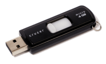
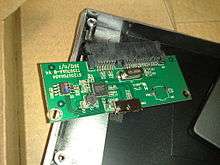
USB implements connections to storage devices using a set of standards called the USB mass storage device class (MSC or UMS). This was at first intended for traditional magnetic and optical drives and has been extended to support flash drives. It has also been extended to support a wide variety of novel devices as many systems can be controlled with the familiar metaphor of file manipulation within directories. The process of making a novel device look like a familiar device is also known as extension. The ability to boot a write-locked SD card with a USB adapter is particularly advantageous for maintaining the integrity and non-corruptible, pristine state of the booting medium.
Though most computers since mid-2004 can boot from USB mass storage devices, USB is not intended as a primary bus for a computer's internal storage. Buses such as Parallel ATA (PATA or IDE), Serial ATA (SATA), or SCSI fulfill that role in PC class computers. However, USB has one important advantage, in that it is possible to install and remove devices without rebooting the computer (hot-swapping), making it useful for mobile peripherals, including drives of various kinds (given SATA or SCSI devices may or may not support hot-swapping).
Firstly conceived and still used today for optical storage devices (CD-RW drives, DVD drives, etc.), several manufacturers offer external portable USB hard disk drives, or empty enclosures for disk drives. These offer performance comparable to internal drives, limited by the current number and types of attached USB devices, and by the upper limit of the USB interface (in practice about 30 MB/s for USB 2.0 and potentially 400 MB/s or more[49] for USB 3.0). These external drives typically include a "translating device" that bridges between a drive's interface to a USB interface port. Functionally, the drive appears to the user much like an internal drive. Other competing standards for external drive connectivity include eSATA, ExpressCard, FireWire (IEEE 1394), and most recently Thunderbolt.
Another use for USB mass storage devices is the portable execution of software applications (such as web browsers and VoIP clients) with no need to install them on the host computer.[50][51]
Media Transfer Protocol
Media Transfer Protocol (MTP) was designed by Microsoft to give higher-level access to a device's filesystem than USB mass storage, at the level of files rather than disk blocks. It also has optional DRM features. MTP was designed for use with portable media players, but it has since been adopted as the primary storage access protocol of the Android operating system from the version 4.1 Jelly Bean as well as Windows Phone 8 (Windows Phone 7 devices had used the Zune protocol which was an evolution of MTP). The primary reason for this is that MTP does not require exclusive access to the storage device the way UMS does, alleviating potential problems should an Android program request the storage while it is attached to a computer. The main drawback is that MTP is not as well supported outside of Windows operating systems.
Human interface devices
Joysticks, keypads, tablets and other human-interface devices (HIDs) are also progressively migrating from MIDI, and PC game port connectors to USB.
USB mice and keyboards can usually be used with older computers that have PS/2 connectors with the aid of a small USB-to-PS/2 adapter. For mice and keyboards with dual-protocol support, an adaptor that contains no logic circuitry may be used: the hardware in the USB keyboard or mouse is designed to detect whether it is connected to a USB or PS/2 port, and communicate using the appropriate protocol. Converters also exist that connect PS/2 keyboards and mice (usually one of each) to a USB port.[52] These devices present two HID endpoints to the system and use a microcontroller to perform bidirectional data translation between the two standards.
Device Firmware Upgrade
Device Firmware Upgrade (DFU) is a vendor- and device-independent mechanism for upgrading the firmware of USB devices with improved versions provided by their manufacturers, offering (for example) a way for firmware bugfixes to be deployed. During the firmware upgrade operation, USB devices change their operating mode effectively becoming a PROM programmer. Any class of USB device can implement this capability by following the official DFU specifications.[48][53][54]
In addition to its intended legitimate purposes, DFU can also be exploited by uploading maliciously crafted firmwares that cause USB devices to spoof various other device types; one such exploiting approach is known as BadUSB.[55]
Connectors
Connector properties

The connectors the USB committee specifies support a number of USB's underlying goals, and reflect lessons learned from the many connectors the computer industry has used.
Receptacles and plugs
The connector mounted on the host or device is called the receptacle, and the connector attached to the cable is called the plug.[56] The official USB specification documents also periodically define the term male to represent the plug, and female to represent the receptacle.[57]
Usability and orientation

By design, it is difficult to insert a USB plug into its receptacle incorrectly. The USB specification states that the required USB icon must be embossed on the "topside" of the USB plug, which "...provides easy user recognition and facilitates alignment during the mating process." The specification also shows that the "recommended" "Manufacturer's logo" ("engraved" on the diagram but not specified in the text) is on the opposite side of the USB icon. The specification further states, "The USB Icon is also located adjacent to each receptacle. Receptacles should be oriented to allow the icon on the plug to be visible during the mating process." However, the specification does not consider the height of the device compared to the eye level height of the user, so the side of the cable that is "visible" when mated to a computer on a desk can depend on whether the user is standing or kneeling.[56]
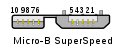
While connector interfaces can be designed to allow plugging with either orientation, the original design omitted such functionality to decrease manufacturing costs. Ajay Bhatt, who was involved in the original USB design team, is working on a new design to make the plug insertable either side up.[58] The reversible type-C plug is an addition to the USB 3.1 specification; it is slightly taller but also narrower than, making it comparable to, the Micro-B SuperSpeed connector.[59]
Only moderate force is needed to insert or remove a USB cable. USB cables and small USB devices are held in place by the gripping force from the receptacle (without need of the screws, clips, or thumb-turns other connectors have required).
Power-use topology
The standard connectors were deliberately intended to enforce the directed topology of a USB network: type-A receptacles on host devices that supply power and type-B receptacles on target devices that draw power. This prevents users from accidentally connecting two USB power supplies to each other, which could lead to short circuits and dangerously high currents, circuit failures, or even fire. USB does not support cyclic networks and the standard connectors from incompatible USB devices are themselves incompatible.[6]
However, some of this directed topology is lost with the advent of multi-purpose USB connections (such as USB On-The-Go in smartphones, and USB-powered Wi-Fi routers), which require A-to-A, B-to-B, and sometimes Y/splitter cables. See the USB On-The-Go connectors section below, for a more detailed summary description.
Durability
The standard connectors were designed to be robust. Because USB is hot-pluggable, the connectors would be used more frequently, and perhaps with less care, than other connectors. Many previous connector designs were fragile, specifying embedded component pins or other delicate parts that were vulnerable to bending or breaking. The electrical contacts in a USB connector are protected by an adjacent plastic tongue, and the entire connecting assembly is usually protected by an enclosing metal sheath.[60]
The connector construction always ensures that the external sheath on the plug makes contact with its counterpart in the receptacle before any of the four connectors within make electrical contact. The external metallic sheath is typically connected to system ground, thus dissipating damaging static charges. This enclosure design also provides a degree of protection from electromagnetic interference to the USB signal while it travels through the mated connector pair (the only location when the otherwise twisted data pair travels in parallel). In addition, because of the required sizes of the power and common connections, they are made after the system ground but before the data connections. This type of staged make-break timing allows for electrically safe hot-swapping.[60]
The newer Micro-USB receptacles are designed for a minimum rated lifetime of 10,000 cycles of insertion and removal between the receptacle and plug, compared to 1,500 for the standard USB and 5,000 for the Mini-USB receptacle. Features intended to accomplish include, a locking device was added and the leaf-spring was moved from the jack to the plug, so that the most-stressed part is on the cable side of the connection. This change was made so that the connector on the less expensive cable would bear the most wear instead of the more expensive Micro-USB device.[8][60] However the idea that these changes did in fact make the connector more durable in real world use has been widely disputed, with many contending that they are in fact, much less durable.[8]
Compatibility
The USB standard specifies relatively loose tolerances for compliant USB connectors to minimize physical incompatibilities in connectors from different vendors. To address a weakness present in some other connector standards, the USB specification also defines limits to the size of a connecting device in the area around its plug. This was done to prevent a device from blocking adjacent ports due to the size of the cable strain relief mechanism (usually molding integral with the cable outer insulation) at the connector. Compliant devices must either fit within the size restrictions or support a compliant extension cable that does.
In general, USB cables have only plugs on their ends, while hosts and devices have only receptacles. Hosts almost universally have Type-A receptacles, while devices have one or another Type-B variety. Type-A plugs mate only with Type-A receptacles, and the same applies to their Type-B counterparts; they are deliberately physically incompatible. However, an extension to the USB standard specification called USB On-The-Go (OTG) allows a single port to act as either a host or a device, which is selectable by the end of the cable that plugs into the receptacle on the OTG-enabled unit. Even after the cable is hooked up and the units are communicating, the two units may "swap" ends under program control. This capability is meant for units such as PDAs in which the USB link might connect to a PC's host port as a device in one instance, yet connect as a host itself to a keyboard and mouse device in another instance.
USB 3.0 connectors
Standard-A and type-A plugs and receptacles are designed to interoperate. Standard-B plugs and receptacles are somewhat larger than type-B; thus, type-B plugs can fit into standard-B receptacles, while the opposite is not possible.
Connector types

- Micro-B plug
- UC-E6[lower-alpha 1]
- Mini-B plug
- type-A receptacle[lower-alpha 2]
- type-A plug
- type-B plug
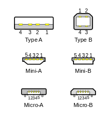
There are several types of USB connector, including some that have been added while the specification progressed. The original USB specification detailed standard-A and standard-B plugs and receptacles; the B connector was necessary so that cabling could be plug ended at both ends and still prevent users from connecting one computer receptacle to another. The first engineering change notice to the USB 2.0 specification added Mini-B plugs and receptacles.
The data pins in the standard plugs are actually recessed in the plug compared to the outside power pins. This permits the power pins to connect first, preventing data errors by allowing the device to power up first and then establish the data connection. Also, some devices operate in different modes depending on whether the data connection is made.
To reliably enable a charge-only feature, modern USB accessory peripherals now include charging cables that provide power connections to the host port but no data connections, and both home and vehicle charging docks are available that supply power from a converter device and do not include a host device and data pins, allowing any capable USB device to charge or operate from a standard USB cable.
In a charge-only cable, the data wires are shorted at the device end. These wires are usually green and white. If these wires are left as-is, the device will often reject the charger as unsuitable.
Standard connectors
The type-A plug has an elongated rectangular cross-section, inserts into a type-A receptacle on a downstream port on a USB host or hub, and carries both power and data. Captive cables on USB devices, such as keyboards or mice, will be terminated with a type-A plug.
The type-B plug has a near square cross-section with the top exterior corners beveled. As part of a removable cable, it inserts into an upstream port on a device, such as a printer. On some devices, the type-B receptacle has no data connections, being used solely for accepting power from the upstream device. This two-connector-type scheme (A/B) prevents a user from accidentally creating an electrical loop.[61]
The spring contacts in the connectors eventually relax and wear out with repeated cycles of plugging and unplugging. The lifetime of a type-A plug is approximately 1,500 connect/disconnect cycles.[62]
The maximum allowed cross-section of the overmold boot (which is part of the connector used for its handling) is 16 by 8 mm for the standard-A plug type, while for the type-B it is 11.5 by 10.5 mm.[63]
Mini and micro connectors
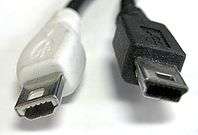
Various connectors have been used for smaller devices such as digital cameras, smartphones, and tablet computers. These include the now-deprecated[64] (i.e. de-certified but standardized) Mini-A and Mini-AB connectors; Mini-B connectors are still supported, but are not On-The-Go-compliant.[65] The Mini-B USB connector was standard for transferring data to and from the early smartphones and PDAs. Both Mini-A and Mini-B plugs are approximately 3 by 7 mm; the Mini-A connector and the Mini-AB receptacle connector were deprecated on 23 May 2007.[66]
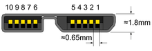
The Micro-USB connector was announced by the USB-IF on 4 January 2007.[7][67] Micro-USB plugs have a similar width to Mini-USB, but approximately half the thickness, enabling their integration into thinner portable devices. The Micro-A connector is 6.85 by 1.8 mm with a maximum overmold boot size of 11.7 by 8.5 mm, while the Micro-B connector is 6.85 by 1.8 mm with a maximum overmold size of 10.6 by 8.5 mm.[68]
The thinner micro connectors are intended to replace the mini connectors in new devices including smartphones, personal digital assistants, and cameras.[69] While some of the devices and cables still use the older mini variant, the newer micro connectors are widely adopted, and as of December 2010 they are the most widely used.
The micro plug design is rated for at least 10,000 connect-disconnect cycles, which is more than the mini plug design.[7][70] The micro connector is also designed to reduce the mechanical wear on the device; instead the easier-to-replace cable is designed to bear the mechanical wear of connection and disconnection. The Universal Serial Bus Micro-USB Cables and Connectors Specification details the mechanical characteristics of Micro-A plugs, Micro-AB receptacles (which accept both Micro-A and Micro-B plugs), and Micro-B plugs and receptacles,[70] along with a standard-A receptacle to Micro-A plug adapter.
The cellular phone carrier group Open Mobile Terminal Platform (OMTP) in 2007 endorsed Micro-USB as the standard connector for data and power on mobile devices[71] On 22 October 2009 the International Telecommunication Union (ITU) announced that it had embraced Micro-USB as the Universal Charging Solution its "energy-efficient one-charger-fits-all new mobile phone solution," and added: "Based on the Micro-USB interface, UCS chargers also include a 4-star or higher efficiency rating—
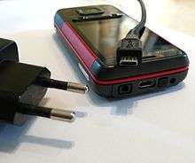
The European Standardisation Bodies CEN, CENELEC and ETSI (independent of the OMTP/GSMA proposal) defined a common External Power Supply (EPS) for use with smartphones sold in the EU based on Micro-USB.[73] 14 of the world's largest mobile phone manufacturers signed the EU's common EPS Memorandum of Understanding (MoU).[74][75] Apple, one of the original MoU signers, makes Micro-USB adapters available – as permitted in the Common EPS MoU – for its iPhones equipped with Apple's proprietary 30-pin dock connector or (later) Lightning connector.[76][77]
Lately a new micro connector plug has been developed by Winner Gear (crowdfunded on Indiegogo) with no functional enhancement to the USB itself but offering a reversible plug that can be connected to existing Micro-B sockets. There are a number of manufacturers offering USB-A to reversible Micro-B cables as well as OTG to reversible Micro-B cables.
USB On-The-Go connectors
All current USB On-The-Go (OTG) devices are required to have one, and only one, USB connector: a Micro-AB receptacle. Non-OTG compliant devices are not allowed to use the Micro-AB receptacle, due to power supply shorting hazards on the VBUS line. The Micro-AB receptacle is capable of accepting both Micro-A and Micro-B plugs, attached to any of the legal cables and adapters as defined in revision 1.01 of the Micro-USB specification. Prior to the development of Micro-USB, USB On-The-Go devices were required to use Mini-AB receptacles to perform the equivalent job.
To enable Type-AB receptacles to distinguish which end of a cable is plugged in, mini and micro plugs have an "ID" pin in addition to the four contacts found in standard-size USB connectors. This ID pin is connected to GND in Type-A plugs, and left unconnected in Type-B plugs. Typically, a pull-up resistor in the device is used to detect the presence or absence of an ID connection.
The OTG device with the A-plug inserted is called the A-device and is responsible for powering the USB interface when required and by default assumes the role of host. The OTG device with the B-plug inserted is called the B-device and by default assumes the role of peripheral. An OTG device with no plug inserted defaults to acting as a B-device. If an application on the B-device requires the role of host, then the Host Negotiation Protocol (HNP) is used to temporarily transfer the host role to the B-device.
OTG devices attached either to a peripheral-only B-device or a standard/embedded host have their role fixed by the cable, since in these scenarios it is only possible to attach the cable one way.
Host and device interface receptacles
USB plugs fit one receptacle with notable exceptions for USB On-The-Go "AB" support and the general backwards compatibility of USB 3.0 as shown.
| |
Plug | |||||||||
|---|---|---|---|---|---|---|---|---|---|---|
 |
 |
 |
 |
 |
 |
 |
 |
 |
| |
 |
Yes | Only non- SuperSpeed |
No | No | No | No | No | No | No | No |
| Type-A SuperSpeed |
Only non- SuperSpeed |
Yes | No | No | No | No | No | No | No | No |
 |
No | No | Yes | No | No | No | No | No | No | No |
| Type-B SuperSpeed |
No | No | Only non- SuperSpeed |
Yes | No | No | No | No | No | No |
| |
No | No | No | No | Deprecated | No | No | No | No | No |
| |
No | No | No | No | Deprecated | Deprecated | No | No | No | No |
| |
No | No | No | No | No | Yes | No | No | No | No |
| |
No | No | No | No | No | No | Yes | Yes | No | No |
| |
No | No | No | No | No | No | No | Yes | No | No |
 Micro-B SuperSpeed |
No | No | No | No | No | No | No | Only non- SuperSpeed |
Yes | No |
| |
No | No | No | No | No | No | No | No | No | Yes |
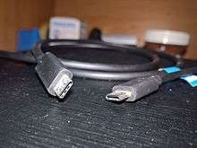
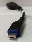
Cables and their connectors
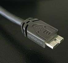
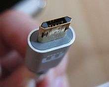
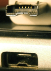
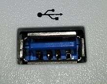
USB 3.0 introduced new standard and micro-sized Type-A and Type-B plugs and receptacles. The 3.0 receptacles are backward-compatible with the corresponding pre-3.0 plugs. See the Micro-B cable plug photo on the right. The Micro-B 3.0 plug effectively consists of a standard USB 1.x/2.0 Micro-B cable plug, with an additional five-pin plug "stacked" to the side of it. In this way, USB 3.0 Micro-A host connectors can achieve backward compatibility with the USB 1.x/2.0 Micro-B cable plugs.
USB cables exist with various combinations of plugs on each end of the cable, as displayed below. Notes from the section above apply here as well.
| Plugs, each end | |
|
|
|
|
|
Micro-B SuperSpeed |
|
|---|---|---|---|---|---|---|---|---|
| |
Non- standard |
Non- standard |
Non- standard |
Yes | Yes | Yes | Yes | Yes |
| |
Non- standard |
No | No | Deprecated | Deprecated | Non- standard |
No | No |
| |
Non- standard |
No | No | Non- standard |
Non- standard |
Yes | No | No |
| |
Yes | Deprecated | Non- standard |
No | No | No | No | Yes |
| |
Yes | Deprecated | Non- standard |
No | Non- standard |
No | No | Yes |
| |
Yes | Non- standard |
Yes | No | No | No | No | Yes |
| Micro-B SuperSpeed |
Yes | No | No | No | No | No | No | Yes |
| |
Yes | No | No | Yes | Yes | Yes | Yes | Yes |
- Non-standard
- Existing for specific proprietary purposes, and in most cases not inter-operable with USB-IF compliant equipment. In addition to the above cable assemblies comprising two plugs, an "adapter" cable with a Micro-A plug and a standard-A receptacle is compliant with USB specifications.[68] Other combinations of connectors are not compliant.There do exist A-to-A assemblies, referred to as cables (such as the Easy Transfer Cable); however, these have a pair of USB devices in the middle, making them more than just cables.
- Deprecated
- Some older devices and cables with Mini-A connectors have been certified by USB-IF. The Mini-A connector is obsolete: no new Mini-A connectors and neither Mini-A nor Mini-AB receptacles will be certified.[64]Note: Mini-B is not deprecated, but less and less used since the arrival of Micro-B.
Pinouts
USB is a serial bus, using four shielded wires for the USB 2.0 variant: two for power (VBUS and GND), and two for differential data signals (labelled as D+ and D− in pinouts). Non-Return-to-Zero Inverted (NRZI) encoding scheme is used for transferring data, with a sync field to synchronize the host and receiver clocks. D+ and D− signals are transmitted on a differential pair, providing half-duplex data transfers for USB 2.0. Mini and micro connectors have their GND connections moved from pin #4 to pin #5, while their pin #4 serves as an ID pin for the On-The-Go host/client identification.[78]
USB 3.0 provides two additional differential pairs (four wires, SSTx+, SSTx−, SSRx+ and SSRx−), providing full-duplex data transfers at SuperSpeed, which makes it similar to Serial ATA or single-lane PCI Express.
- Power (VBUS, 5 V)
- Data− (D−)
- Data+ (D+)
- ID (On-The-Go)
- GND
- SuperSpeed transmit− (SSTx−)
- SuperSpeed transmit+ (SSTx+)
- GND
- SuperSpeed receive− (SSRx−)
- SuperSpeed receive+ (SSRx+)
| Pin | Name | Wire color | Description | |
|---|---|---|---|---|
| 1 | VBUS | Red, or | Orange | +5 V |
| 2 | D− | White, or | Gold | Data− |
| 3 | D+ | Green | Data+ | |
| 4 | GND | Black, or | Blue | Ground |
| Pin | Name | Wire color | Description |
|---|---|---|---|
| 1 | VBUS | Red | +5 V |
| 2 | D− | White | Data− |
| 3 | D+ | Green | Data+ |
| 4 | ID | No wire | On-The-Go ID distinguishes cable ends:
|
| 5 | GND | Black | Signal ground |
Proprietary connectors and formats
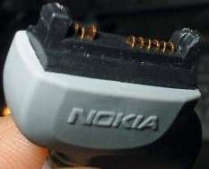
Manufacturers of personal electronic devices might not include a USB standard connector on their product for technical or marketing reasons.[79] Some manufacturers provide proprietary cables that permit their devices to physically connect to a USB standard port. Full functionality of proprietary ports and cables with USB standard ports is not assured; for example, some devices only use the USB connection for battery charging and do not implement any data transfer functions.[80]
-
HTC ExtMicro USB port and connector
-

An Apple Lightning-to-USB adapter and captive USB cable
Colors
| Color | Description | ||||||
|---|---|---|---|---|---|---|---|
| Black or white | Type-A or type-B | ||||||
| Blue (Pantone 300C) | Type-A or type-B, SuperSpeed | ||||||
| Teal blue | Type-A or type-B, SuperSpeed+ | ||||||
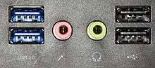
| Yellow, orange or red | Ports only. High-current or sleep-and-charge | ||||||
USB ports and connectors are often color-coded to distinguish their different functions and USB versions. These colors are not part of the USB specification and can vary between manufacturers; for example, USB 3.0 specification mandates appropriate color-coding while it only recommends blue inserts for standard-A USB 3.0 connectors and plugs.[81]
Cabling
The D± signals used by low, full, and high speed are carried over a twisted pair (typically, unshielded) to reduce noise and crosstalk. SuperSpeed uses separate transmit and receive differential pairs, which additionally require shielding (typically, shielded twisted pair but twinax is also mentioned by the specification). Thus, to support SuperSpeed data transmission, cables contain twice as many wires and are thus larger in diameter.[82]
The USB 1.1 standard specifies that a standard cable can have a maximum length of 3 meters with devices operating at full speed (12 Mbit/s), and a maximum length of 5 meters with devices operating at low speed (1.5 Mbit/s).[83][84]
USB 2.0 provides for a maximum cable length of 5 meters for devices running at high speed (480 Mbit/s). The primary reason for this limit is the maximum allowed round-trip delay of about 1.5 μs. If USB host commands are unanswered by the USB device within the allowed time, the host considers the command lost. When adding USB device response time, delays from the maximum number of hubs added to the delays from connecting cables, the maximum acceptable delay per cable amounts to 26 ns.[85] The USB 2.0 specification requires that cable delay be less than 5.2 ns per meter (192000 km/s, which is close to the maximum achievable transmission speed for standard copper wire).
The USB 3.0 standard does not directly specify a maximum cable length, requiring only that all cables meet an electrical specification: for copper cabling with AWG 26 wires the maximum practical length is 3 meters (9.8 ft).[86]
Power
| Specification | Current | Voltage | Power |
|---|---|---|---|
| Low-power device | 100 mA | 5 V | 0.50 W |
| Low-power SuperSpeed (USB 3.0) device | 150 mA | 5 V | 0.75 W |
| High-power device | 500 mA[lower-alpha 1] | 5 V | 2.5 W |
| High-power SuperSpeed (USB 3.0) device | 900 mA[lower-alpha 2] | 5 V | 4.5 W |
| Battery Charging (BC) 1.2 | 5 A | 5 V | 25 W |
| Type-C[lower-alpha 3] | 1.5 A | 5 V | 7.5 W |
| 3 A | 5 V | 15 W | |
| Power Delivery micro-format[lower-alpha 3] | 3 A | 20 V | 60 W |
| Power Delivery standard format or Type-C[lower-alpha 4][lower-alpha 3] | 5 A | 20 V | 100 W |

USB supplies bus power across VBUS and GND at a nominal voltage 5 V ± 5%, at supply, to power USB devices. Power is sourced solely from upstream devices or hosts, and is consumed solely by downstream devices. USB provides for various voltage drops and losses in providing bus power. As such, the voltage at the hub port is specified to be in the range 5.00+0.25
−0.60 V by USB 2.0, and 5.00+0.25
−0.55 V[87] by USB 3.0. It is specified that devices' configuration and low-power functions must operate down to 4.40 V at the hub port by USB 2.0 and that devices' configuration, low-power, and high-power functions must operate down to 4.00 V at the device port by USB 3.0.
There are limits on the power a device may draw, stated in terms of a unit load, which is 100 mA, or 150 mA for SuperSpeed devices. There are low-power and high-power devices. Low-power devices may draw at most 1 unit load, and all devices must act as low-power devices when, starting out as, unconfigured. High-power devices draw at least 1 unit load and at most 5 unit loads (500 mA), or 6 unit loads (900 mA) for SuperSpeed devices. A high-powered device must be configured, and may only draw as much power as specified in its configuration.[88][89][90][91] I.e., the maximum power may not be available.
A bus-powered hub is a high-power device providing low-power ports. It draws 1 unit load for the hub controller and 1 unit load for each of at most 4 ports. The hub may also have some non-removable functions in place of ports. A self-powered hub is a device that provides high-power ports. Optionally, the hub controller draw power for its operation as a low-power device, but all high-power ports draw from the hub's self-power.
Where devices (for example, high-speed disk drives) require more power than a high-power device can draw,[92] they function erratically, if at all, from bus power of a single port. USB provides for these devices as being self-powered. However, such devices may come with a Y-shaped cable that has 2 USB plugs (1 for power and data, the other for only power), so as to draw power as 2 devices.[93] Such a cable is non-standard, with the USB compliance specification stating that "use of a 'Y' cable (a cable with two A-plugs) is prohibited on any USB peripheral", meaning that "if a USB peripheral requires more power than allowed by the USB specification to which it is designed, then it must be self-powered."[94]
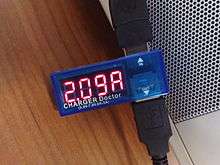
USB Battery Charging
_meter_2.jpg)
USB Battery Charging defines a new port type, the charging port, as opposed to the standard downstream port (SDP) of the base specification. Charging ports are divided into 2 further types: the charging downstream port (CDP), which has data signals, and the dedicated charging port (DCP), which does not. Dedicated charging ports can be found on USB power adapters that convert utility power or another power source (e.g., a car's electrical system) to run attached devices and battery packs. On a host (such as a laptop computer) with both standard and charging USB ports, the charging ports should be labeled as such.[95]
The charging device identifies the type of port through non-data signalling on the D+ and D− signals immediately after attach. A DCP simply has to place a resistance not exceeding 200 Ω across the D+ and D− signals.[95][96]
Per the base specification, any device attached to an SDP must initially be a low-power device, with high-power mode contingent on later USB configuration by the host. Charging ports, however, can immediately supply up to at least 1.5 A. More current may be supplied up to the maximum current of 5 A, but the charging port may apply current limiting, or even shut down. The maximum current is determined by the over-current protection maximum current in the baseline specification. Note that it is specified only that USB connectors are tested to a contact current rating of at least 1.5 A.[95]
These bus power currents being much higher than cables were designed for, though not unsafe, cause a larger voltage between the ends of the ground signal, significantly reducing noise margins causing problems with High Speed signalling. Battery Charging 1.1 specifies that charging devices must dynamically limit bus power current draw during High Speed signalling;[97] 1.2 simply specifies that charging devices and ports must be designed to tolerate the higher ground voltage difference in High Speed signalling.
Revision 1.2 of the specification was released in 2010. Several changes are made and limits are increased including allowing 1.5 A on charging downstream ports for unconfigured devices, allowing High Speed communication while having a current up to 1.5 A, and allowing a maximum current of 5 A. Also, support is removed for charging port detection via resistive mechanisms.[28]
Before the battery charging specification was defined, there was no standardized way for the portable device to inquire how much current was available. For example, Apple's iPod and iPhone chargers indicate the available current by voltages on the D− and D+ lines. When D+ = D− = 2.0 V, the device may pull up to 500 mA. When D+ = 2.0 V and D− = 2.8 V, the device may pull up to 1 A of current.[98] When D+ = 2.8 V and D− = 2.0 V, the device may pull up to 2 A of current.[99]
Accessory charging adaptors (ACA)
Portable devices having an On The Go port may want to charge and access USB peripheral at the same time, but having only a single port (both due to On The Go and space requirement) prevents this. Accessory charging adapters (ACA) are devices which allow a charging power to be injected into an On The Go connection between host and peripheral.
ACAs have three ports: the OTG port for the portable device, which is required to have a Micro-A plug on a captive cable; the accessory port, which is required to have a Micro-AB or type-A receptacle; and the charging port, which is required to have a Micro-B receptacle, or type-A plug or charger on a captive cable. The ID pin of the OTG port is not connected within plug as usual, but to the ACA itself, where signals outside the OTG floating and ground states are used for ACA detection and state signalling. The charging port does not pass data, but does use the D± signals for charging port detection. The accessory port acts as any other port. When appropriately signalled by the ACA, the portable device can charge from the bus power as if there were a charging port present; any OTG signals over bus power are instead passed to the portable device via the ID signal. Bus power is also provided to the accessory port from the charging port transparently.[95]
Power Delivery (PD)
| Profile | +5 V | +12 V | +20 V |
|---|---|---|---|
| 0 | Reserved | ||
| 1 | 2.0 A, 10 W[lower-alpha 1] | No | No |
| 2 | 1.5 A, 18 W | ||
| 3 | 3.0 A, 36 W | ||
| 4 | 3.0 A, 60 W | ||
| 5 | 5.0 A, 60 W | 5.0 A, 100 W | |
| |||
| Source output power (W) |
Current, at: (A) | |||
|---|---|---|---|---|
| +5 V | +9 V | +15 V | +20 V | |
| 0.5–15 | 0.1–3.0 | No | No | No |
| 15–27 | 3.0 (15 W) |
1.7–3.0 | ||
| 27–45 | 3.0 (27 W) |
1.8–3.0 | ||
| 45–60 | 3.0 (45 W) |
2.25–3.0 | ||
| 60–100 | 3.0–5.0 | |||
In July 2012, the USB Promoters Group announced the finalization of the USB Power Delivery (PD) specification, an extension that specifies using certified PD aware USB cables with standard USB Type-A and Type-B connectors to deliver increased power (more than 7.5 W) to devices with larger power demand. Devices can request higher currents and supply voltages from compliant hosts – up to 2 A at 5 V (for a power consumption of up to 10 W), and optionally up to 3 A or 5 A at either 12 V (36 W or 60 W) or 20 V (60 W or 100 W).[102] In all cases, both host-to-device and device-to-host configurations are supported.[103]
The intent is to permit uniformly charging laptops, tablets, USB-powered disks and similarly higher-power consumer electronics, as a natural extension of existing European and Chinese mobile telephone charging standards. This may also affect the way electric power used for small devices is transmitted and used in both residential and public buildings.[58][104]
The Power Delivery specification defines six fixed power profiles for the power sources. PD-aware devices implement a flexible power management scheme by interfacing with the power source through a bidirectional data channel and requesting a certain level of electrical power, variable up to 5 A and 20 V depending on supported profile. The power configuration protocol uses a 24 MHz BFSK-coded transmission channel on the VBUS line.
The USB Power Delivery revision 2.0 specification has been released as part of the USB 3.1 suite.[105] It covers the Type-C cable and connector with four power/ground pairs and a separate configuration channel, which now hosts a DC coupled low-frequency BMC-coded data channel that reduces the possibilities for RF interference.[106] Power Delivery protocols have been updated to facilitate Type-C features such as cable ID function, Alternate Mode negotiation, increased VBUS currents, and VCONN-powered accessories.
As of USB Power Delivery Revision 2.0 Version 1.2, the six fixed power profiles for power sources have been deprecated.[107] USB PD Power Rules replace power profiles, defining four normative voltage levels at 5V, 9V, 15V, and 20V. Instead of six fixed profiles, power supplies may support any maximum source output power from 0.5W to 100W.[101]
Status of available product: Currently (April, 2016) there are silicon controllers available from several sources (TI, Cypress) [108][109] and several others. Power supplies bundled with Type-C based laptops from Apple, Google, HP, Dell, and Razer support USB PD.[110] In addition, accessories from third party vendors including Anker,[111] Belkin,[112][113] iVoler[114] and Innergie[115] support USB PD 2.0 at multiple voltages. There are several PD aware projects such as the USB-PD Sniffer[116] that are PD aware. ASUS also make a fully Power Delivery compliant adapter card the USB 3.1 UPD PANEL[117]
List of 60W/100W USB Chargeable Laptops
Sleep-and-charge ports
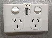
Sleep-and-charge USB ports can be used to charge electronic devices even when the computer is switched off. Normally, when a computer is powered off the USB ports are powered down, preventing phones and other devices from charging. Sleep-and-charge USB ports remain powered even when the computer is off. On laptops, charging devices from the USB port when it is not being powered from AC drains the laptop battery faster; most laptops have a facility to stop charging if their own battery charge level gets too low.[118] This feature has also been implemented on some laptop docking stations allowing device charging even when no laptop is present.[119]
Sleep-and-charge USB ports may be found colored differently than regular ports, mostly red or yellow, though that is not always the case.
On Dell and Toshiba laptops, the port is marked with the standard USB symbol with an added lightning bolt icon on the right side. Dell calls this feature PowerShare,[120] while Toshiba calls it USB Sleep-and-Charge.[121] On Acer Inc. and Packard Bell laptops, sleep-and-charge USB ports are marked with a non-standard symbol (the letters USB over a drawing of a battery); the feature is simply called Power-off USB.[122] On some laptops such as Dell and Apple MacBook models, it is possible to plug a device in, close the laptop (putting it into sleep mode) and have the device continue to charge.
Mobile device charger standards
In China
As of 14 June 2007, all new mobile phones applying for a license in China are required to use a USB port as a power port for battery charging.[123][124] This was the first standard to use the convention of shorting D+ and D−.[125]
OMTP/GSMA Universal Charging Solution
In September 2007, the Open Mobile Terminal Platform group (a forum of mobile network operators and manufacturers such as Nokia, Samsung, Motorola, Sony Ericsson and LG) announced that its members had agreed on Micro-USB as the future common connector for mobile devices.[126][127]
The GSM Association (GSMA) followed suit on 17 February 2009,[128][128][129][130][131] and on 22 April 2009, this was further endorsed by the CTIA – The Wireless Association,[132] with the International Telecommunication Union (ITU) announcing on 22 October 2009 that it had also embraced the Universal Charging Solution as its "energy-efficient one-charger-fits-all new mobile phone solution," and added: "Based on the Micro-USB interface, UCS chargers will also include a 4-star or higher efficiency rating—up to three times more energy-efficient than an unrated charger."[133]
EU Smartphone Power Supply Standard
In June 2009, many of the world's largest mobile phone manufacturers signed an EC-sponsored Memorandum of Understanding (MoU), agreeing to make most data-enabled mobile phones marketed in the European Union compatible with a common External Power Supply (EPS). The EU's common EPS specification (EN 62684:2010) references the USB Battery Charging standard and is similar to the GSMA/OMTP and Chinese charging solutions.[134][135] In January 2011, the International Electrotechnical Commission (IEC) released its version of the (EU's) common EPS standard as IEC 62684:2011.[136]
Non-standard devices
Some USB devices require more power than is permitted by the specifications for a single port. This is common for external hard and optical disc drives, and generally for devices with motors or lamps. Such devices can use an external power supply, which is allowed by the standard, or use a dual-input USB cable, one input of which is used for power and data transfer, the other solely for power, which makes the device a non-standard USB device. Some USB ports and external hubs can, in practice, supply more power to USB devices than required by the specification but a standard-compliant device may not depend on this.
In addition to limiting the total average power used by the device, the USB specification limits the inrush current (i.e., that used to charge decoupling and filter capacitors) when the device is first connected. Otherwise, connecting a device could cause problems with the host's internal power. USB devices are also required to automatically enter ultra low-power suspend mode when the USB host is suspended. Nevertheless, many USB host interfaces do not cut off the power supply to USB devices when they are suspended.[137]
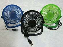
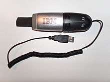
Some non-standard USB devices use the 5 V power supply without participating in a proper USB network, which negotiates power draw with the host interface. These are usually called USB decorations. Examples include USB-powered keyboard lights, fans, mug coolers and heaters, battery chargers, miniature vacuum cleaners, and even miniature lava lamps. In most cases, these items contain no digital circuitry, and thus are not standard compliant USB devices. This may cause problems with some computers, such as drawing too much current and damaging circuitry. Prior to the Battery Charging Specification, the USB specification required that devices connect in a low-power mode (100 mA maximum) and communicate their current requirements to the host, which then permits the device to switch into high-power mode.
Some devices, when plugged into charging ports, draw even more power (10 watts at 2.1 amperes) than the Battery Charging Specification allows — The iPad is one such device.[138] Barnes & Noble NOOK Color devices also require a special charger that runs at 1.9 amperes.[139]
PoweredUSB
PoweredUSB is a proprietary extension that adds four additional pins supplying up to 6 A at 5 V, 12 V, or 24 V. It is commonly used in point of sale systems to power peripherals such as barcode readers, credit card terminals, and printers.
Signaling
USB allows the following signaling rates (the terms speed and bandwidth are used interchangeably, while high- is alternatively written as hi-):
- A low-speed rate of 1.5 Mbit/s is defined by USB 1.0. It is very similar to full-bandwidth operation except each bit takes 8 times as long to transmit. It is intended primarily to save cost in low-bandwidth human interface devices (HID) such as keyboards, mice, and joysticks.
- The full-speed (FS) rate of 12 Mbit/s is the basic USB data rate defined by USB 1.0. All USB hubs can operate at this speed.
- A high-speed (HS) rate of 480 Mbit/s was introduced in 2001. All hi-speed devices are capable of falling back to full-bandwidth operation if necessary; i.e., they are backward compatible with USB 1.1. Connectors are identical for USB 2.0 and USB 1.x.
- A SuperSpeed (SS) rate of 5.0 Gbit/s. The written USB 3.0 specification was released by Intel and its partners in August 2008. The first USB 3.0 controller chips were sampled by NEC in May 2009,[140] and the first products using the USB 3.0 specification arrived in January 2010.[141] USB 3.0 connectors are generally backward compatible, but include new wiring and full duplex operation.
USB signals are transmitted using differential signaling on a twisted-pair data cable with 90 Ω ± 15% characteristic impedance.[142]
- Low- and full-speed modes use a single data pair, labeled D+ and D−, in half-duplex. Transmitted signal levels are 0.0–0.3 V for logical low, and 2.8–3.6 V for logical high level. The signal lines are not terminated.
- High-speed mode uses the same wire pair, but with different electrical conventions. Lower signal voltages of −10 – 10 mV for low and 360 – 440 mV for logical high level, and termination of 45 Ω to ground, or 90 Ω differential to match the data cable impedance.
- SuperSpeed adds two additional pairs of shielded twisted wire (and new, mostly compatible expanded connectors), dedicated to full-duplex SuperSpeed operation. The half-duplex lines are still used for configuration.
A USB connection is always between a host or hub at the A connector end, and a device or hub's "upstream" port at the other end. Originally, this was a B connector, preventing erroneous loop connections, but additional upstream connectors were specified, and some cable vendors designed and sold cables that permitted erroneous connections (and potential damage to circuitry). USB interconnections are not as fool-proof or as simple as originally intended.
The host includes 15 kΩ pull-down resistors on each data line. When no device is connected, this pulls both data lines low into the so-called single-ended zero state (SE0 in the USB documentation), and indicates a reset or disconnected connection.
A USB device pulls one of the data lines high with a 1.5 kΩ resistor. This overpowers one of the pull-down resistors in the host and leaves the data lines in an idle state called J. For USB 1.x, the choice of data line indicates what signal rates the device is capable of; full-bandwidth devices pull D+ high, while low-bandwidth devices pull D− high. The K state is just the opposite polarity to the J state.
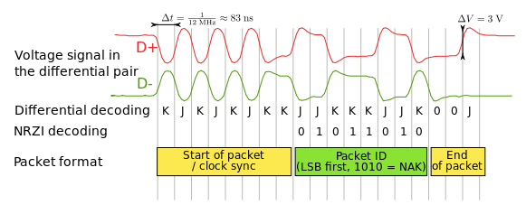
USB data is transmitted by toggling the data lines between the J state and the opposite K state. USB encodes data using the NRZI line coding; a 0 bit is transmitted by toggling the data lines from J to K or vice versa, while a 1 bit is transmitted by leaving the data lines as-is. To ensure a minimum density of signal transitions remains in the bitstream, USB uses bit stuffing; an extra 0 bit is inserted into the data stream after any appearance of six consecutive 1 bits. Seven consecutive received 1 bits is always an error. USB 3.0 has introduced additional data transmission encodings.
A USB packet begins with an 8-bit synchronization sequence, 00000001₂. That is, after the initial idle state J, the data lines toggle KJKJKJKK. The final 1 bit (repeated K state) marks the end of the sync pattern and the beginning of the USB frame. For high bandwidth USB, the packet begins with a 32-bit synchronization sequence.
A USB packet's end, called EOP (end-of-packet), is indicated by the transmitter driving 2 bit times of SE0 (D+ and D− both below max.) and 1 bit time of J state. After this, the transmitter ceases to drive the D+/D− lines and the aforementioned pull up resistors hold it in the J (idle) state. Sometimes skew due to hubs can add as much as one bit time before the SE0 of the end of packet. This extra bit can also result in a "bit stuff violation" if the six bits before it in the CRC are 1s. This bit should be ignored by receiver.
A USB bus is reset using a prolonged (10 to 20 milliseconds) SE0 signal.
USB 2.0 devices use a special protocol during reset, called chirping, to negotiate the high bandwidth mode with the host/hub. A device that is HS capable first connects as an FS device (D+ pulled high), but upon receiving a USB RESET (both D+ and D− driven LOW by host for 10 to 20 ms) it pulls the D− line high, known as chirp K. This indicates to the host that the device is high bandwidth. If the host/hub is also HS capable, it chirps (returns alternating J and K states on D− and D+ lines) letting the device know that the hub operates at high bandwidth. The device has to receive at least three sets of KJ chirps before it changes to high bandwidth terminations and begins high bandwidth signaling. Because USB 3.0 uses wiring separate and additional to that used by USB 2.0 and USB 1.x, such bandwidth negotiation is not required.
Clock tolerance is 480.00±0.24 Mbit/s, 12.00±0.03 Mbit/s, 1.50±0.18 Mbit/s.
Though high bandwidth devices are commonly referred to as "USB 2.0" and advertised as "up to 480 Mbit/s," not all USB 2.0 devices are high bandwidth. The USB-IF certifies devices and provides licenses to use special marketing logos for either "basic bandwidth" (low and full) or high bandwidth after passing a compliance test and paying a licensing fee. All devices are tested according to the latest specification, so recently compliant low bandwidth devices are also 2.0 devices.
USB 3 uses tinned copper stranded AWG-28 cables with 90±7 Ω impedance for its high-speed differential pairs and linear feedback shift register and 8b/10b encoding sent with a voltage of 1 V nominal with a 100 mV receiver threshold; the receiver uses equalization.[143] SSC clock and 300 ppm precision is used. Packet headers are protected with CRC-16, while data payload is protected with CRC-32.[144] Power up to 3.6 W may be used. One unit load in superspeed mode is equal to 150 mA.[144]
Transmission rates
| Mode | Gross data rate | Introduced in |
|---|---|---|
| Low Speed | 1.5 Mbit/s | USB 1.0 |
| Full Speed | 12 Mbit/s | USB 1.0 |
| High Speed Also, Hi-Speed | 480 Mbit/s | USB 2.0 |
| SuperSpeed | 5 Gbit/s | USB 3.0 |
| SuperSpeed+ | 10 Gbit/s | USB 3.1 |
The theoretical maximum data rate in USB 2.0 is 480 Mbit/s (60 MB/s) per controller and is shared amongst all attached devices. Some chipset manufacturers overcome this bottleneck by providing multiple USB 2.0 controllers within the southbridge.
According to routine testing performed by CNet, write operations to typical Hi-Speed hard drives can sustain rates of 25–30 MB/s, while read operations are at 30–42 MB/s;[145] this is 70% of the total available bus bandwidth. For USB 3.0, typical write speed is 70–90 MB/s, while read speed is 90–110 MB/s.[145] Mask tests, also known as eye diagram tests, are used to determine the quality of a signal in the time domain. They are defined in the referenced document as part of the electrical test description for the high-speed (HS) mode at 480 Mbit/s.[146]
According to a USB-IF chairman, "at least 10 to 15 percent of the stated peak 60 MB/s (480 Mbit/s) of Hi-Speed USB goes to overhead—the communication protocol between the card and the peripheral. Overhead is a component of all connectivity standards".[147] Tables illustrating the transfer limits are shown in Chapter 5 of the USB spec.
For isochronous devices like audio streams, the bandwidth is constant, and reserved exclusively for a given device. The bus bandwidth therefore only has an effect on the number of channels that can be sent at a time, not the "speed" or latency of the transmission.
Latency
For low-speed (1.5 Mbit/s) and full-speed (12 Mbit/s) devices the shortest time for a transaction in one direction is 1 ms.[148] High-speed (480 Mbit/s) uses transactions within each micro frame (125 µs)[149] where using 1-byte interrupt packet results in a minimal response time of 940 ns. 4-byte interrupt packet results in 984 ns.
Communication
During USB communication, data is transmitted as packets. Initially, all packets are sent from the host, via the root hub and possibly more hubs, to devices. Some of those packets direct a device to send some packets in reply.
After the sync field, all packets are made of 8-bit bytes, transmitted least-significant bit first. The first byte is a packet identifier (PID) byte. The PID is actually 4 bits; the byte consists of the 4-bit PID followed by its bitwise complement. This redundancy helps detect errors. (Note also that a PID byte contains at most four consecutive 1 bits, and thus never needs bit-stuffing, even when combined with the final 1 bit in the sync byte. However, trailing 1 bits in the PID may require bit-stuffing within the first few bits of the payload.)
| Type | PID value (msb-first) | Transmitted byte (lsb-first) | Name | Description |
|---|---|---|---|---|
| Reserved | 0000 | 0000 1111 | ||
| Token | 1000 | 0001 1110 | SPLIT | High-bandwidth (USB 2.0) split transaction |
| 0100 | 0010 1101 | PING | Check if endpoint can accept data (USB 2.0) | |
| Special | 1100 | 0011 1100 | PRE | Low-bandwidth USB preamble |
| Handshake | ERR | Split transaction error (USB 2.0) | ||
| 0010 | 0100 1011 | ACK | Data packet accepted | |
| 1010 | 0101 1010 | NAK | Data packet not accepted; please retransmit | |
| 0110 | 0110 1001 | NYET | Data not ready yet (USB 2.0) | |
| 1110 | 0111 1000 | STALL | Transfer impossible; do error recovery | |
| Token | 0001 | 1000 0111 | OUT | Address for host-to-device transfer |
| 1001 | 1001 0110 | IN | Address for device-to-host transfer | |
| 0101 | 1010 0101 | SOF | Start of frame marker (sent each ms) | |
| 1101 | 1011 0100 | SETUP | Address for host-to-device control transfer | |
| Data | 0011 | 1100 0011 | DATA0 | Even-numbered data packet |
| 1011 | 1101 0010 | DATA1 | Odd-numbered data packet | |
| 0111 | 1110 0001 | DATA2 | Data packet for high-bandwidth isochronous transfer (USB 2.0) | |
| 1111 | 1111 0000 | MDATA | Data packet for high-bandwidth isochronous transfer (USB 2.0) |
Packets come in three basic types, each with a different format and CRC (cyclic redundancy check):
Handshake packets
Handshake packets consist of only a single PID byte, and are generally sent in response to data packets. Error detection is provided by transmitting four bits that represent the packet type twice, in a single PID byte using complemented form. Three basic types are ACK, indicating that data was successfully received, NAK, indicating that the data cannot be received and should be retried, and STALL, indicating that the device has an error condition and cannot transfer data until some corrective action (such as device initialization) occurs.[150][151]
USB 2.0 added two additional handshake packets: NYET and ERR. NYET indicates that a split transaction is not yet complete, while ERR handshake indicates that a split transaction failed. A second use for a NYET packet is to tell the host that the device has accepted a data packet, but cannot accept any more due to full buffers. This allows a host to switch to sending small PING tokens to inquire about the device's readiness, rather than sending an entire unwanted DATA packet just to elicit a NAK.[150][151]
The only handshake packet the USB host may generate is ACK. If it is not ready to receive data, it should not instruct a device to send.
Token packets
Token packets consist of a PID byte followed by two payload bytes: 11 bits of address and a five-bit CRC. Tokens are only sent by the host, never a device.
IN and OUT tokens contain a seven-bit device number and four-bit function number (for multifunction devices) and command the device to transmit DATAx packets, or receive the following DATAx packets, respectively. An IN token expects a response from a device. The response may be a NAK or STALL response, or a DATAx frame. In the latter case, the host issues an ACK handshake if appropriate. An OUT token is followed immediately by a DATAx frame. The device responds with ACK, NAK, NYET, or STALL, as appropriate.
SETUP operates much like an OUT token, but is used for initial device setup. It is followed by an eight-byte DATA0 frame with a standardized format.
Every millisecond (12000 full-bandwidth bit times), the USB host transmits a special SOF (start of frame) token, containing an 11-bit incrementing frame number in place of a device address. This is used to synchronize isochronous and interrupt data transfers. High-bandwidth USB 2.0 devices receive seven additional SOF tokens per frame, each introducing a 125 µs "microframe" (60000 high-bandwidth bit times each).
USB 2.0 added PING token, which asks a device if it is ready to receive an OUT/DATA packet pair. PING is usually sent by a host when polling a device that most recently responded with NAK or NYET. This avoids the need to send a large data packet to a device that the host suspects to be unwilling to accept it.[152] The device responds with ACK, NAK or STALL, as appropriate.
USB 2.0 also added a larger three-byte SPLIT token with a seven-bit hub number, 12 bits of control flags, and a five-bit CRC. This is used to perform split transactions. Rather than tie up the high-bandwidth USB bus sending data to a slower USB device, the nearest high-bandwidth capable hub receives a SPLIT token followed by one or two USB packets at high bandwidth, performs the data transfer at full or low bandwidth, and provides the response at high bandwidth when prompted by a second SPLIT token.
Data packets
A data packet consists of the PID followed by 0–1,024 bytes of data payload (up to 1,024 bytes for high-speed devices, up to 64 bytes for full-speed devices, and at most eight bytes for low-speed devices),[153] and a 16-bit CRC.
There are two basic forms of data packet, DATA0 and DATA1. A data packet must always be preceded by an address token, and is usually followed by a handshake token from the receiver back to the transmitter. The two packet types provide the 1-bit sequence number required by stop-and-wait ARQ. If a USB host does not receive a response (such as an ACK) for data it has transmitted, it does not know if the data was received or not; the data might have been lost in transit, or it might have been received but the handshake response was lost.
To solve this problem, the device keeps track of the type of DATAx packet it last accepted. If it receives another DATAx packet of the same type, it is acknowledged but ignored as a duplicate. Only a DATAx packet of the opposite type is actually received.
If the data is corrupted while transmitted or received, the CRC check fails. When this happens, the receiver does not generate an ACK, which makes the sender resend the packet.[154]
When a device is reset with a SETUP packet, it expects an 8-byte DATA0 packet next.
USB 2.0 added DATA2 and MDATA packet types as well. They are used only by high-bandwidth devices doing high-bandwidth isochronous transfers that must transfer more than 1024 bits per 125 µs micro frame (8,192 kbit/s).
PRE packet
Low-bandwidth devices are supported with a special PID value, PRE. This marks the beginning of a low-bandwidth packet, and is used by hubs that normally do not send full-bandwidth packets to low-bandwidth devices. Since all PID bytes include four 0 bits, they leave the bus in the full-bandwidth K state, which is the same as the low-bandwidth J state. It is followed by a brief pause, during which hubs enable their low-bandwidth outputs, already idling in the J state. Then a low-bandwidth packet follows, beginning with a sync sequence and PID byte, and ending with a brief period of SE0. Full-bandwidth devices other than hubs can simply ignore the PRE packet and its low-bandwidth contents, until the final SE0 indicates that a new packet follows.
Audio streaming
The USB Device Working Group has laid out specifications for audio streaming. Although USB technology wasn't designed with audio streaming in mind, specific standards have been developed and implemented for audio class uses.
The DWG distinguishes two audio device modes[155] specifications: Audio 1.0 specification and Audio 2.0 specification. Three types of devices are defined:
- USB headphone devices
- USB microphone devices
- USB headset devices
Three levels of synchronisation were defined: asynchronous, synchronous, and adaptive.[156]
Comparisons with other connection methods

FireWire
At first, USB was considered a complement to IEEE 1394 (FireWire) technology, which was designed as a high-bandwidth serial bus that efficiently interconnects peripherals such as disk drives, audio interfaces, and video equipment. In the initial design, USB operated at a far lower data rate and used less sophisticated hardware. It was suitable for small peripherals such as keyboards and pointing devices.
The most significant technical differences between FireWire and USB include:
- USB networks use a tiered-star topology, while IEEE 1394 networks use a tree topology.
- USB 1.0, 1.1 and 2.0 use a "speak-when-spoken-to" protocol; peripherals cannot communicate with the host unless the host specifically requests communication. USB 3.0 allows for device-initiated communications towards the host. A FireWire device can communicate with any other node at any time, subject to network conditions.
- A USB network relies on a single host at the top of the tree to control the network. In a FireWire network, any capable node can control the network.
- USB runs with a 5 V power line, while FireWire in current implementations supplies 12 V and theoretically can supply up to 30 V.
- Standard USB hub ports can provide from the typical 500 mA/2.5 W of current, only 100 mA from non-hub ports. USB 3.0 and USB On-The-Go supply 1.8 A/9.0 W (for dedicated battery charging, 1.5 A/7.5 W Full bandwidth or 900 mA/4.5 W High Bandwidth), while FireWire can in theory supply up to 60 watts of power, although 10 to 20 watts is more typical.
These and other differences reflect the differing design goals of the two buses: USB was designed for simplicity and low cost, while FireWire was designed for high performance, particularly in time-sensitive applications such as audio and video. Although similar in theoretical maximum transfer rate, FireWire 400 is faster than USB 2.0 Hi-Bandwidth in real-use,[157] especially in high-bandwidth use such as external hard drives.[158][159][160][161] The newer FireWire 800 standard is twice as fast as FireWire 400 and faster than USB 2.0 Hi-Bandwidth both theoretically and practically.[162] However, Firewire's speed advantages rely on low-level techniques such as direct memory access (DMA), which in turn have created opportunities for security exploits such as the DMA attack.
The chipset and drivers used to implement USB and FireWire have a crucial impact on how much of the bandwidth prescribed by the specification is achieved in the real world, along with compatibility with peripherals.[163]
Ethernet
The IEEE 802.3af Power over Ethernet (PoE) standard specifies a more elaborate power negotiation scheme than powered USB. It operates at 48 V DC and can supply more power (up to 12.95 W, PoE+ 25.5 W) over a cable up to 100 meters compared to USB 2.0, which provides 2.5 W with a maximum cable length of 5 meters. This has made PoE popular for VoIP telephones, security cameras, wireless access points and other networked devices within buildings. However, USB is cheaper than PoE provided that the distance is short, and power demand is low.
Ethernet standards require electrical isolation between the networked device (computer, phone, etc.) and the network cable up to 1500 V AC or 2250 V DC for 60 seconds.[164] USB has no such requirement as it was designed for peripherals closely associated with a host computer, and in fact it connects the peripheral and host grounds. This gives Ethernet a significant safety advantage over USB with peripherals such as cable and DSL modems connected to external wiring that can assume hazardous voltages under certain fault conditions.[165]
MIDI
Digital musical instruments are another example where USB is competitive for low-cost devices. However Power over Ethernet and the MIDI plug standard have an advantage in high-end devices that may have long cables. USB can cause ground loop problems between equipment, because it connects ground references on both transceivers. By contrast, the MIDI plug standard and Ethernet have built-in isolation to 500V or more.
eSATA/eSATAp
The eSATA connector is a more robust SATA connector, intended for connection to external hard drives and SSDs. eSATA's transfer rate (up to 6 Gbit/s) is similar to that of USB 3.0 (up to 5 Gbit/s on current devices; 10 Gbit/s speeds via USB 3.1, announced on 31 July 2013). A device connected by eSATA appears as an ordinary SATA device, giving both full performance and full compatibility associated with internal drives.
eSATA does not supply power to external devices. This is an increasing disadvantage compared to USB. Even though USB 3.0's 4.5 W is sometimes insufficient to power external hard drives, technology is advancing and external drives gradually need less power, diminishing the eSATA advantage. eSATAp (power over eSATA; aka ESATA/USB) is a connector introduced in 2009 that supplies power to attached devices using a new, backward compatible, connector. On a notebook eSATAp usually supplies only 5 V to power a 2.5-inch HDD/SSD; on a desktop workstation it can additionally supply 12 V to power larger devices including 3.5-inch HDD/SSD and 5.25-inch optical drives.
eSATAp support can be added to a desktop machine in the form of a bracket connecting to motherboard SATA, power, and USB resources.
eSATA, like USB, supports hot plugging, although this might be limited by OS drivers and device firmware.
Thunderbolt
Thunderbolt combines PCI Express and Mini DisplayPort into a new serial data interface. Original Thunderbolt implementations have two channels, each with a transfer speed of 10 Gbit/s, resulting in an aggregate unidirectional bandwidth of 20 Gbit/s.[166]
Thunderbolt 2 uses link aggregation to combine the two 10 Gbit/s channels into one bi-directional 20 Gbit/s channel.
Thunderbolt 3 is announced to use USB Type-C connectors.[167][168][169] Thunderbolt 3 has one 40 Gbit/s channel.
Interoperability
Various protocol converters are available that convert USB data signals to and from other communications standards.
Related standards
The USB Implementers Forum is working on a wireless networking standard based on the USB protocol. Wireless USB is a cable-replacement technology, and uses ultra-wideband wireless technology for data rates of up to 480 Mbit/s.
USB 2.0 High-Speed Inter-Chip (HSIC) is a chip-to-chip variant of USB 2.0 that eliminates the conventional analog transceivers found in normal USB. It was adopted as a standard by the USB Implementers Forum in 2007. The HSIC physical layer uses about 50% less power and 75% less board area compared to traditional USB 2.0. HSIC uses two signals at 1.2 V and has a throughput of 480 Mbit/s. Maximum PCB trace length for HSIC is 10 cm. It does not have low enough latency to support RAM memory sharing between two chips.[170][171]
The USB 3.0 successor of HSIC is called SuperSpeed Inter-Chip (SSIC).[172]
See also
References
- ↑ "82371FB (PIIX) AND 82371SB (PIIX3) PCI ISA IDE XCELERATOR" (PDF). Intel. May 1996. Retrieved 2016-03-12.
- 1 2 "USB 'A' Plug Form Factor Revision 1.0" (PDF). USB Implementers Forum. 23 March 2005. p. 1. Retrieved 2012-04-04.
Body length is fully 12 mm in width by 4.5 mm in height with no deviations
- ↑ The VBUS supply from a low-powered hub port may drop to 4.40 V
- ↑ "USB deserves more support", Business, Boston Globe Online, Simson, 1995-12-31, retrieved 2011-12-12
- ↑ "Sony Playstation 3 60 GB, Sony Playstation 4 Pro, and Xbox One S", Reviews, CNet
- 1 2 "USB connector guide". C2G. Retrieved 2013-12-02.
- 1 2 3 4 Universal Serial Bus Cables and Connectors Class Document (PDF), Revision 2.0, USB Implementers Forum, August 2007, p. 6, retrieved 2014-08-17
- 1 2 3 "Why was Mini-USB deprecated in favor of Micro-USB?". stackexchange.com. 2011. Retrieved 2013-12-03.
- ↑ Icon design recommendation for Identifying USB 2.0 Ports on PCs, Hosts and Hubs http://www.usb.org/developers/docs/icon_design.pdf
- ↑ Janssen, Cory. "What is a Universal Serial Bus (USB)?". Techopedia. Retrieved 2014-02-12.
- ↑ Ajay Bhatt: Fellow (biography), Intel
- ↑ Rogoway, Mark (2009-05-09). "Intel ad campaign remakes researchers into rock stars". The Oregonian. Retrieved 2009-09-23.
- 1 2 Pan, Hui; Polishuk, Paul (eds.). 1394 Monthly Newsletter. Information Gatekeepers. pp. 7–9. GGKEY:H5S2XNXNH99. Retrieved 2012-10-23.
- ↑ Seebach, Peter (26 April 2005). "Standards and specs: The ins and outs of USB". IBM. Archived from the original on 2010-01-10. Retrieved 2012-09-08.
- 1 2 "Eight ways the iMac changed computing".
- 1 2 "Compaq hopes to follow the iMac". Archived from the original on 22 October 2006.
- 1 2 "The PC Follows iMac's Lead".
- 1 2 Hearst Magazines (February 2001). Popular Mechanics: Making Connections. Hearst Magazines. p. 59. ISSN 0032-4558.
- ↑ Universal Serial Bus Specification Revision 3.0: 3.1 (Zip). 9 September 2011. p. 41 (3–1). Retrieved 2011-10-14.08-Sep-2012
- ↑ Universal Serial Bus Specification Revision 3.0: 1.6 (Zip). 9 September 2011. p. 31 (1–3). Retrieved 2011-10-14.
- 1 2 "USB 3.0 SuperSpeed gone wild at CES 2010, trumps even your new SSD". 9 January 2010. Retrieved 2011-02-20.
- ↑ "USB 3.0 Finally Arrives". 11 January 2010. Retrieved 2011-02-20.
- ↑ "SuperSpeed USB 3.0: More Details Emerge". PC world. 6 January 2009.
- ↑ "IEC and USB-IF Expand Cooperation to Support Next-Generation High-Speed Data Delivery and Device Charging Applications" (PDF) (Press release). GENEVA, Switzerland and BEAVERTON, Ore., U.S. December 8, 2014.
- 1 2 3 http://www.usb.org/developers/ssusb/USB_3_1_Language_Product_and_Packaging_Guidelines_FINAL.pdf
- ↑ "5.5.4". Universal Serial Bus Specification (PDF) (Technical report). 2000. p. 40. v2.0.
- ↑ "USB Implementers Forum".
- 1 2 3 "Battery Charging v1.2 Spec and Adopters Agreement" (Zip). USB Implementers Forum. 7 December 2010. Retrieved 2014-10-05.
- ↑ "USB" (PDF) (Press release). Implementers Forum. 2008-11-17. Retrieved 2010-06-22.
- ↑ "USB 3.0 Technology" (PDF). HP. 2012. Retrieved 2014-01-02.
- ↑ "Universal Serial Bus 3.0 Specification" (PDF). USB Implementers Forum. 2008-11-12. Retrieved 2012-12-29.
- ↑ "SuperSpeed USB (USB 3.0) Performance to Double with New Capabilities" (PDF) (Press release). Implementers Forum. 2013-01-06.
- ↑ "SuperSpeed USB 10 Gbps – Ready for Development" (PDF) (Press release). Hillsboro, Ore. July 31, 2013. Archived from the original (PDF) on 2016-01-27.
- ↑ "SuperSpeed USB 10 Gbps - Ready for Development". Rock Hill Herald. Archived from the original on 11 October 2014. Retrieved 2013-07-31.
- ↑ "Synopsys Demonstrates Industry's First SuperSpeed USB 10 Gbps Platform-to-Platform Host-Device IP Data Transfer" (Press release). Mountain View, California: Synopsys. 2013-12-10. Retrieved 2013-12-23.
As measured by the Ellisys USB Explorer Protocol Analyzer, the IP realized 10 Gbps USB 3.1 effective data rates of more than 900 MBps between two Synopsys HAPS-70 FPGA-based prototyping systems while using backward compatible USB connectors, cables and software.
- 1 2 Howse, Brett (August 12, 2014). "USB Type-C Connector Specifications Finalized". Retrieved December 28, 2014.
- ↑ Hruska, Joel (March 13, 2015). "USB-C vs. USB 3.1: What's the difference?". ExtremeTech. Retrieved April 9, 2015.
- ↑ Ngo, Dong (22 August 2014). "USB Type-C: One Cable to Connect Them All". cnet.com. CNET. Archived from the original on 2015-03-07. Retrieved 28 December 2014.
- ↑ https://web.archive.org/web/20141229123208/https://intel.activeevents.com/sf14/connect/sessionDetail.ww?SESSION_ID=1254. Archived from the original on 29 December 2014. Retrieved 29 December 2014. Missing or empty
|title=(help) - ↑ Smith, Ryan (September 22, 2014). "DisplayPort Alternate Mode for USB Type-C Announced - Video, Power, & Data All Over Type-C". AnandTech. Retrieved 28 December 2014.
- ↑ Universal Serial Bus Type-C Cable and Connector Specification Revision 1.1 (April 3, 2015), section 2.2, page 20
- ↑ Universal Serial Bus Specification Revision 2.0 (Zip). 11 October 2011. pp. 13; 30; 256. Retrieved 2012-09-08.
- ↑ Universal Serial Bus Specification Revision 3.0: 8.8. 9 September 2011. pp. 8–25. Archived from the original (Zip) on 2011-11-04. Retrieved 2011-10-14.08-Sep-2012
- ↑ Dan Froelich (2009-05-20). "Isochronous Protocol" (PDF). usb.org. Retrieved 2014-11-21.
- ↑ "Class Codes". USB Implementers Forum.
- ↑ Use class information in the interface descriptors. This base class is defined to use in device descriptors to indicate that class information should be determined from the Interface Descriptors in the device.
- ↑ "Universal Serial Bus Test and Measurement Class Specification (USBTMC) Revision 1.0". USB Implementers Forum. 14 April 2003.
- 1 2 "Universal Serial Bus Device Class Specification for Device Firmware Upgrade, Version 1.1" (PDF). USB Implementers Forum. 2004-08-05. pp. 8–9. Retrieved 2014-09-08.
- ↑ Universal Serial Bus 3.0 Specification,4.4.11 "Efficiency"
- ↑ "100 Portable Apps for your USB Stick (both for Mac and Win)". Retrieved 2008-10-30.
- ↑ "Skype VoIP USB Installation Guide". Retrieved 2008-10-30.
- ↑ "PS/2 to USB Keyboard and Mouse Adapter".
- ↑ "Universal Serial Bus Device Class Specification for Device Firmware Upgrade, Version 1.0" (PDF). USB Implementers Forum. 1999-05-13. pp. 7–8. Archived from the original (PDF) on 2014-08-24. Retrieved 2014-09-08.
- ↑ "dfu-util: USB Device Firmware Upgrade tool". fedoraproject.org. Retrieved 2014-09-08.
- ↑ Karsten Nohl; Sascha Krißler; Jakob Lell (2014-08-07). "BadUSB – On accessories that turn evil" (PDF). srlabs.de. Retrieved 2014-09-08.
- 1 2 Hewlett-Packard, Intel, Microsoft, NEC, ST-Ericsson, Texas Instruments (6 June 2011). Universal Serial Bus 3.0 Specification: Revision 1.0. p. 531. Retrieved 2011-07-26.
- ↑ "USB 2.0 Specification Engineering Change-USB.org" (PDF). USB Flash Drive Alliance. Retrieved 2014-12-29.
- 1 2 "Edison's revenge". The Economist. 2013-10-19. Retrieved 2013-10-23.
- ↑ Byford, Sam (2013-12-04). "Next USB plug will finally be reversible". The Verge. Retrieved 2013-12-04.
- 1 2 3 "Universal Serial Bus Cables and Connectors Class Document Revision 2.0" (PDF). usb.org. August 2007. Retrieved 2013-12-03.
- ↑ Quinnell, Richard A (24 October 1996). "USB: a neat package with a few loose ends". EDN Magazine. Reed. Retrieved 2013-02-18.
- ↑ "What is the Life Cycle of a USB Flash Drive?". Get USB. 2007-03-08. Retrieved 2011-12-12.
- ↑ "USB 2.0 Specification Engineering Change Notice (ECN) #1: Mini-B connector" (PDF). USB-IF Developers Area. 2000-10-20. Retrieved 2014-12-11.
- 1 2 "Deprecation of the Mini-A and Mini-AB Connectors" (PDF) (Press release). USB Implementers Forum. 2007-05-27. Retrieved 2009-01-13.
- ↑ "ID Pin Resistance on Mini B-plugs and Micro B-plugs Increased to 1 Mohm". USB IF Compliance Updates. December 2009. Retrieved 2010-03-01.
- ↑ "Deprecation of the Mini-A and Mini-AB Connectors" (PDF) (Press release). USB Implementers Forum. 2007-05-23. Retrieved 2010-12-23.
- ↑ "Mobile phones to adopt new, smaller USB connector" (PDF) (Press release). USB Implementers Forum. 2007-01-04. Retrieved 2007-01-08.
- 1 2 3 "Universal Serial Bus Micro-USB Cables and Connectors Specification" (PDF). USB Implementers Forum. 2007-04-04. Archived from the original (PDF) on 2015-01-31. Retrieved 2015-01-31.
- ↑ "Micro-USB pinout and list of compatible smartphones and other devices". pinoutsguide.com.
- 1 2 "Universal Serial Bus Micro-USB Cables and Connectors Specification to the USB 2.0 Specification, Revision 1.01" (PDF). USB Implementers Forum. 2007-04-07. Archived from the original (Zip) on 2007-04-08. Retrieved 2010-11-18.
Section 1.3: Additional requirements for a more rugged connector that is durable past 10,000 cycles and still meets the USB 2.0 specification for mechanical and electrical performance was also a consideration. The Mini-USB could not be modified and remain backward compatible to the existing connector as defined in the USB OTG specification.
- ↑ "OMTP Local Connectivity: Data Connectivity". Open Mobile Terminal Platform. 17 September 2007. Archived from the original on 15 October 2008. Retrieved 2009-02-11.
- ↑ "Universal phone charger standard approved—One-size-fits-all solution will dramatically cut waste and GHG emissions". ITU (press release). Pressinfo. 2009-10-22. Retrieved 2009-11-04.
- ↑ "Commission welcomes new EU standards for common mobile phone charger". Press Releases. Europa. 2010-12-29. Retrieved 2011-05-22.
- ↑ New EU standards for common mobile phone charger (press release), Europa
- ↑ The following 10 biggest mobile phone companies have signed the MoU: Apple, LG, Motorola, NEC, Nokia, Qualcomm, Research In Motion, Samsung, Sony Ericsson, Texas Instruments (press release), Europa
- ↑ "Nice Micro-USB adapter Apple, now sell it everywhere", Giga om, 5 October 2011
- ↑ "Apple's Lightning to Micro-USB adapter now available in US, not just Europe anymore", Engadget, 2012-11-03
- ↑ "USB Pinout". usbpinout.net. Retrieved 2014-06-23.
- ↑ "Proprietary Cables vs Standard USB". anythingbutipod.com. 2008-04-30. Retrieved 2013-10-29.
- ↑ Lex Friedman (2013-02-25). "Review: Logitech's Ultrathin mini keyboard cover makes the wrong tradeoffs". macworld.com. Retrieved 2013-10-29.
- ↑ "Universal Serial Bus Revision 3.0 Specification, Sections 3.1.1.1 and 5.3.1.3" (ZIP). urb.org. Retrieved 2014-05-19.
- ↑ "What is the USB 3.0 Cable Difference". Hantat. 2009-05-18. Retrieved 2011-12-12.
- ↑ "USB Cable Length Limitations" (PDF). cablesplususa.com. 2010-11-03. Retrieved 2014-02-02.
- ↑ "Cables and Long-Haul Solutions". USB FAQ. USB.org. Retrieved 2014-02-02.
- ↑ "USB Frequently Asked Questions". USB Implementers Forum. Retrieved 2010-12-10.
- ↑ Axelson, Jan. "USB 3.0 Developers FAQ". Retrieved 2016-10-20.
- ↑ "7.3.2 Bus Timing/Electrical Characteristics". Universal Serial Bus Specification. USB.org.
- ↑ "USB.org". USB.org. Retrieved 2010-06-22.
- ↑ "Universal Serial Bus 1.1 Specification" (PDF). cs.ucr.edu. 1998-09-23. pp. 150, 158. Retrieved 2014-11-24.
- ↑ "Universal Serial Bus 2.0 Specification, Section 7.2.1.3 Low-power Bus-powered Functions" (ZIP). usb.org. 2000-04-27. Retrieved 2014-01-11.
- ↑ "Universal Serial Bus 2.0 Specification, Section 7.2.1.4 High-power Bus-powered Functions" (ZIP). usb.org. 2000-04-27. Retrieved 2014-01-11.
- ↑ "Roundup: 2.5-inch Hard Disk Drives with 500 GB, 640 GB and 750 GB Storage Capacities (page 17)". xbitlabs.com. 2010-06-16. Retrieved 2010-07-09.
- ↑ "I have the drive plugged in but I cannot find the drive in "My Computer", why?". hitachigst.com. Retrieved 2012-03-30.
- ↑ "USB-IF Compliance Updates". Compliance.usb.org. 2011-09-01. Retrieved 2014-01-22.
- 1 2 3 4 "Battery Charging Specification, Revision 1.2". USB Implementers Forum. 7 December 2010. Retrieved 2016-03-29.
- ↑ Section 1.4.5, pg. 2; and Table 5-3 "Resistances", pg. 45
- ↑ "Battery Charging Specification, Revision 1.1". USB Implementers Forum. 15 April 2009. Archived from the original on 29 March 2014. Retrieved 2009-09-23.
- ↑ "The mysteries of Apple device charging", Minty Boost, Lady Ada, 2011
- ↑ Modify a cheap USB charger to feed an iPod, iPhone, 2013
- ↑ "PD_1.0" (PDF). Retrieved 2016-04-27.
- 1 2 "10 Power Rules", Universal Serial Bus Power Delivery Specification revision 2.0, version 1.2, USB Implementers Forum, 2016-03-25, retrieved 2016-04-09
- ↑ Burgess, Rick. "USB 3.0 SuperSpeed update to eliminate need for chargers". TechSpot.
- ↑ "USB 3.0 Promoter Group Announces Availability of USB Power Delivery Specification" (PDF). 2012-07-18. Retrieved 2013-01-16.
- ↑ "USB Power Delivery — Introduction" (PDF). 2012-07-16. Retrieved 2013-01-06.
- ↑ "USB 3.1 Specification". Retrieved 2014-11-11.
- ↑ "USB Future Specifications Industry Reviews" (PDF). Retrieved 2014-08-10.
- ↑ "A. Power Profiles", Universal Serial Bus Power Delivery Specification revision 2.0, version 1.2, USB Implementers Forum, 2016-03-25, retrieved 2016-04-09
- ↑ "Texas Instruments" (PDF). Retrieved 2016-04-01.
- ↑ "Cypess". Retrieved 2016-04-01.
- ↑ http://www.pcworld.com/article/3017182/hardware/usb-c-charging-universal-or-bust-we-plug-in-every-device-we-have-to-chase-the-dream.html
- ↑ http://gtrusted.com/review/anker-powerport-5-usb-c-with-usb-power-delivery
- ↑ http://www.prnewswire.com/news-releases/belkin-launches-usb-c-car-charger--cable-with-power-delivery-300281277.html
- ↑ http://gtrusted.com/review/belkin-usb-c-car-charger-cable-the-worlds-first-car-charger-with-power-delivery-goes-the-distance
- ↑ http://gtrusted.com/review/ivoler-75w-usb-type-c-charger-with-power-delivery
- ↑ http://www.slashgear.com/innergie-powergear-usb-c-45-charger-supports-multiple-voltages-30416319/
- ↑ "USB-PD Sniffer".
- ↑ "ASUS UPD 3.1".
- ↑ "Toshiba NB200 User Manual" (PDF). UK. 2009-03-01. Retrieved 2014-01-26.
- ↑ "ThinkPad Ultra Dock". lenovo.com. Retrieved 16 September 2016.
- ↑ "USB PowerShare Feature". dell.com. 2013-06-05. Retrieved 2013-12-04.
- ↑ "USB Sleep-and-Charge Ports". toshiba.com. Retrieved 2014-12-21.
- ↑ "USB Charge Manager". packardbell.com. Retrieved 2014-04-25.
- ↑ Cai Yan (2007-05-31). "China to enforce universal cell phone charger". EE Times. Retrieved 2007-08-25.
- ↑ The Chinese FCC's technical standard: "YD/T 1591-2006, Technical Requirements and Test Method of Charger and Interface for Mobile Telecommunication Terminal Equipment" (PDF) (in Chinese). Dian yuan.
- ↑ Lam, Crystal; Liu, Harry (22 October 2007). "How to conform to China's new mobile phone interface standards". Wireless Net DesignLine. Retrieved 2010-06-22.
- ↑ "Pros seem to outdo cons in new phone charger standard". News. 20 September 2007. Retrieved 2007-11-26.
- ↑ "Broad Manufacturer Agreement Gives Universal Phone Cable Green Light" (Press release). OTMP. 17 September 2007. Retrieved 2007-11-26.
- 1 2 "Agreement on Mobile phone Standard Charger" (Press release). GSM World.
- ↑ "Common Charging and Local Data Connectivity". Open Mobile Terminal Platform. 11 February 2009. Archived from the original on 29 March 2009. Retrieved 2009-02-11.
- ↑ "Universal Charging Solution ~ GSM World". GSM world. Retrieved 2010-06-22.
- ↑ "Meeting the challenge of the universal charge standard in mobile phones". Planet Analog. Retrieved 2010-06-22.
- ↑ "The Wireless Association Announces One Universal Charger Solution to Celebrate Earth Day" (Press release). CTIA. 2009-04-22. Retrieved 2010-06-22.
- ↑ "ITU" (Press release). 2009-10-22. Retrieved 2010-06-22.
- ↑ "chargers". EU: EC. 2009-06-29. Retrieved 2010-06-22.
- ↑ "Europe gets universal cellphone charger in 2010". Wired. 2009-06-13. Retrieved 2010-06-22.
- ↑ "One size-fits-all mobile phone charger: IEC publishes first globally relevant standard". International Electrotechnical Commission. 2011-02-01. Retrieved 2012-02-20.
- ↑ "Part 2 - Electrical". MQP Electronics Ltd. Retrieved 2014-12-29.
- ↑ "Watt to Know About iPhone & iPad Power Adapters | Analysis". The Mac Observer. Retrieved 2011-12-12.
- ↑ "Nook Color charger uses special Micro-USB connector". barnesandnoble.com. 2011-07-03.
- ↑ "NEC ready to sample 'world's first' USB 3.0 controller chip". Retrieved 2009-06-15.
- ↑ "When will USB 3.0 products hit the market?". Retrieved 2009-05-11.
- ↑ "USB in a NutShell—Chapter 2—Hardware". Beyond Logic.org. Retrieved 2007-08-25.
- ↑ "Technical Specifications of the USB 3.0 SuperSpeed Cables". 100717 usb3.com
- 1 2 "Universal Serial Bus 3.0 Specification, Rev 1.0 November 12, 2008" (PDF). 100717 usb3.com
- 1 2 "Seagate FreeAgent GoFlex Ultra-portable" (review). CNet. Retrieved 2011-05-22.
- ↑ Schwarz, Rohde (2012-05-25). "USB 2.0 Mask Testing" (PDF). Retrieved 2012-07-12.
- ↑ "USB 2.0's Real Deal", News & Trends, PC World, 2002-02-28
- ↑ "Mouse stuff you ought to know about", Urban terror, 2008-08-09
- ↑ OS dev - Universal Serial Bus, 2011-02-01
- 1 2 "USB Made Simple, Part 3. Data Flow". usbmadesimple.co.uk. 2008. Retrieved 2014-08-17.
- 1 2 "USB in a NutShell, Chapter 3. USB Protocols". beyondlogic.org. 2010-09-17. Retrieved 2014-08-17.
- ↑ "Part 7, High Speed Transactions: Ping Protocol". usbmadesimple.co.uk. 2008. Retrieved 2014-08-16.
- ↑ "USB in a Nut Shell". Chapter 4 - Endpoint Types. Retrieved 2014-09-05.
- ↑ "Debugging Common USB Issues". Retrieved 2013-06-05.
- ↑ www
.usb .org /developers /docs /devclass _docs /BasicAudioDevice-10 .zip - ↑ "32-bit Atmel Microcontroller Application Note" (PDF). Atmel Corporation. 2011. Retrieved 13 April 2016.
- ↑ "FireWire vs. USB 2.0" (PDF). QImaging. Retrieved 2010-07-20.
- ↑ "FireWire vs. USB 2.0 – Bandwidth Tests". Retrieved 2007-08-25.
- ↑ "USB 2.0 vs FireWire". Digit-Life. Retrieved 2007-08-25.
- ↑ Metz, Cade (2003-02-25). "The Great Interface-Off: FireWire Vs. USB 2.0". PC Magazine. Retrieved 2007-08-25.
- ↑ Heron, Robert. "USB 2.0 Versus FireWire". TechTV. Retrieved 2007-08-25.
- ↑ "FireWire vs. USB 2.0". USB Ware. Retrieved 2007-03-19.
- ↑ Key, Gary (2005-11-15). "Firewire and USB Performance". Retrieved 2008-02-01.
- ↑ "802.3, Section 14.3.1.1" (PDF). IEEE.
- ↑ "Powerbook Explodes After Comcast Plugs In Wrong Cable". Consumerist. 2010-03-08. Retrieved 2010-06-22.
- ↑ "How Thunderbolt Technology Works: Thunderbolt Technology Community". Thunderbolttechnology.net. Retrieved 2014-01-22.
- ↑ One port to rule them all: Thunderbolt 3 and USB Type-C join forces, retrieved 2015-06-02
- ↑ Thunderbolt 3 is twice as fast and uses reversible USB-C, retrieved 2015-06-02
- ↑ Thunderbolt 3 embraces USB Type-C connector, doubles bandwidth to 40Gbps, retrieved 2015-06-02
- ↑ "Interchip Connectivity: HSIC, UniPro, HSI, C2C, LLI... oh my!". Retrieved 2011-06-24.
- ↑ "USB High Speed Inter-Chip Interface". Retrieved 2011-06-24.
- ↑ "Transitioning from USB 2.0 HSIC to USB 3.0 SSIC". synopsys.com. Retrieved 2015-08-07.
Further reading
- Axelson, Jan (1 September 2006). USB Mass Storage: Designing and Programming Devices and Embedded Hosts (1st ed.). Lakeview Research. ISBN 978-1-931-44804-8.
- ——— (1 December 2007). Serial Port Complete: COM Ports, USB Virtual COM Ports, and Ports for Embedded Systems (2nd ed.). Lakeview Research. ISBN 978-1-931-44806-2.
- ——— (2015). USB Complete: The Developer's Guide (5th ed.). Lakeview Research. ISBN 978-1-931448-28-4. 524 pp.
- Hyde, John (February 2001). USB Design by Example: A Practical Guide to Building I/O Devices (2nd ed.). Intel Press. ISBN 978-0-970-28465-5.
- "Debugging USB 2.0 for Compliance: It's Not Just a Digital World" (PDF). Technologies Application Note (1382–3). Agilent.
External links
| Wikimedia Commons has media related to USB. |
| The Wikibook Serial Programming:USB Technical Manual has a page on the topic of: USB connectors |
- "USB Implementers Forum".
- "Universal Host Controller Interface (UHCI)" (PDF). Intel.
- "USB 3.0 Standard-A, Standard-B, Powered-B connectors". Pinouts guide.
- "Characterization and compliance test". Agilent.
- Muller, Henk. "How To Create And Program USB Devices," Electronic Design, July 2012
- An Analysis of Throughput Characteristics of Universal Serial Bus, June 1996, by John Garney
- USB 2.0 Protocol Engine, October 2010, by Razi Hershenhoren and Omer Reznik
- Universal serial bus interfaces for data and power:
| General | |
|---|---|
| Standards |
|
| Storage | |
| Peripheral | |
| Audio | |
| Portable | |
| Embedded | |
Interfaces are listed by their speed in the (roughly) ascending order, so the interface at the end of each section should be the fastest. | |