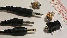
Phone connector (audio)
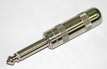
A phone connector, also known as phone jack, audio jack, headphone jack or jack plug, is a common family of electrical connector typically used for analog signals, primarily audio.
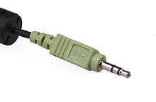
It is cylindrical in shape, typically with two, three, four and, recently, five contacts. Three-contact versions are known as TRS connectors, where T stands for "tip", R stands for "ring" and S stands for "sleeve". Similarly, two-, four- and five- contact versions are called TS, TRRS and TRRRS connectors respectively.
The phone connector was invented for use in telephone switchboards in the 19th century and is still widely used. In its original configuration, the outside diameter of the "sleeve" conductor is 1⁄4 inch (6.35 millimetres). The "mini" connector has a diameter of 3.5 mm (0.14 in) and the "sub-mini" connector has a diameter of 2.5 mm (0.098 in).
Other terms
Specific models are termed stereo plug, mini-stereo, mini jack, headphone jack and microphone jack,[1] or are referred to by size, i.e. 3.5mm or 6.35mm.
In the UK, the terms jack plug and jack socket are commonly used for the respective male and female phone connectors.[2] In the US, a stationary (more fixed) electrical connector is called a "jack".[3][4] The terms phone plug and phone jack are sometimes used to refer to different genders of phone connectors,[5] but are also sometimes used colloquially to refer to RJ11 and older telephone plugs and the corresponding jacks that connect wired telephones to wall outlets.
Phone plugs and jacks are not to be confused with the similar terms phono plug and phono jack (or in the UK, phono socket) which refer to RCA connectors common in consumer hi-fi and audiovisual equipment. The 3.5 mm connector is, however, sometimes—but counter to the connector manufacturers' nomenclature[6]—referred to as mini phono.[7]
Modern connectors
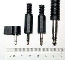
- 2.5 mm mono (TS)
- 3.5 mm mono (TS)
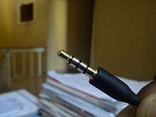
- 3.5 mm stereo (TRS)
- 6.35 mm ( 1⁄4 in) (TRS)
Modern phone connectors are available in three standard sizes. The original 1⁄4 in (6.35 mm) version dates from 1878, when it was used for manual telephone exchanges, making it the oldest electrical connector standard still in use.
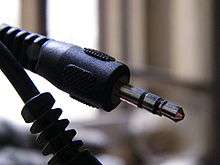
The 3.5 mm or miniature and 2.5 mm or sub-miniature sizes were originally designed as two-conductor connectors for earpieces on transistor radios since the 1950s, the standard still used today.[8] The 3.5 mm connector, which is the most commonly used in portable application today, was popularized by the Sony EFM-117J radio which was released in 1964.[9][10] It became very popular with its application on the Walkman in 1979.
The 3.5 mm and 2.5 mm sizes are sometimes referred to as 1⁄8 in and 3⁄32 in respectively in the United States, though those dimensions are only approximations. All three sizes are now readily available in two-conductor (unbalanced mono) and three-conductor (balanced mono or unbalanced stereo) versions.
Four- and five-conductor versions of the 3.5 mm plug are used for certain applications. A four-conductor version is often used in compact camcorders and portable media players, and sometimes also in laptop computers and smartphones, providing stereo sound plus a video signal. Proprietary interfaces using both four- and five-conductor versions exist, where the extra conductors are used to supply power for accessories. The four-conductor 3.5 mm plug is also used as a speaker-microphone connector on handheld amateur radio transceivers from Yaesu[11] and on some mobile phones.
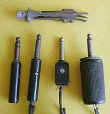
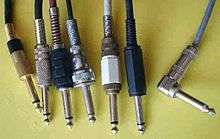
The most common arrangement remains to have the male plug on the cable and the female socket mounted in a piece of equipment: the original intention of the design. A considerable variety of line plugs and panel sockets is available, including plugs suiting various cable sizes, right-angle plugs, and both plugs and sockets in a variety of price ranges and with current capacities up to 15 amperes for certain heavy duty 1⁄4 in versions intended for loudspeaker connections.[12]
Tiny telephone
The professional audio field and the telecommunication industry use tiny telephone (TT) connectors in patch bays. These are mid-size TS or TRS phone plugs with a 4.40 mm (0.173 in) diameter shaft and a slightly different geometry. In the telecommunications field this is termed a "bantam" plug. The three-conductor (TRS) versions are capable of handling balanced line signals and are used in professional audio installations. Though unable to handle as much power, and less reliable than a 6.35 mm (0.250 in) jack,[13] TT connectors are used for professional console and outboard patchbays in studio and live sound applications, where large numbers of patch points are needed in a limited space. The slightly different shape of bantam plugs is also less likely to cause shorting as they are plugged in.
Less common
Less commonly used sizes, both diameters and lengths, are also available from some manufacturers, and are used when it is desired to restrict the availability of matching connectors, such as 0.210 inch inside diameter jacks for fire safety communication jacks in public buildings, the same size found in discontinued Bell & Howell 16 mm projector speaker jacks.[14]
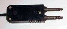
- A two-pin version, known to the telecom industry as a "310 connector" consists of two phone 1⁄4 inch phone plugs at a centre spacing of 0.625 inches. The socket versions of these can be used with normal phone plugs provided the plug bodies are not too large, but the plug version will only mate with two sockets at 0.625 inches centre spacing, or with line sockets, again with sufficiently small bodies. These connectors are still widely used today in telephone company central offices on "DSX" patch panels for DS1 circuits. A similar type of 3.5 mm connector is often used in the armrests of older aircraft, as part of the on-board in-flight entertainment system. Plugging a stereo plug into one of the two mono jacks typically results in the audio coming into only one ear. Adapters are available.
- A short-barrelled version was used for 20th century high-impedance mono headphones, and in particular those used in World War II aircraft. It is physically possible to use a normal plug in a short socket, but a short plug will neither lock into a normal socket nor complete the tip circuit. These have become rare.
Mono and stereo compatibility
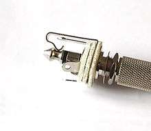
At the top is a three-conductor panel jack.
The original application for the 6.35 mm ( 1⁄4 in) phone jack was in manual telephone exchanges.[15] Many different configurations of these phone plugs were used, some accommodating five or more conductors, with several tip profiles. Of these many varieties, only the two-conductor version with a rounded tip profile was compatible between different manufacturers, and this was the design that was at first adopted for use with microphones, electric guitars, headphones, loudspeakers, and many other items of audio equipment.
When a three-conductor version of the 6.35 mm ( 1⁄4 in) jack was introduced for use with stereo headphones, it was given a sharper tip profile in order to make it possible to manufacture jacks (sockets) that would accept only stereo plugs, to avoid short-circuiting the right channel of the amplifier. This attempt has long been abandoned, and now the normal convention is that all plugs fit all sockets of the same size, regardless of whether they are balanced mono, unbalanced mono or stereo. Most 6.35 mm ( 1⁄4 in) plugs, mono or stereo, now have the profile of the original stereo plug, although a few rounded mono plugs are also still produced. The profiles of stereo miniature and subminiature plugs have always been identical to the mono plugs of the same size.
The results of this physical compatibility are:
- If a two-conductor plug of the same size is connected to a three-conductor socket, the result is that the ring (right channel) of the socket is grounded. This property is deliberately used in several applications. However, grounding one channel may also be dangerous to the equipment if the result is to short circuit the output of the right channel amplifier. In any case, any signal from the right channel is naturally lost.
- If a three-conductor plug is connected to a two-conductor socket, normally the result is to leave the ring of the plug unconnected (open circuit). In the days of vacuum tubes this was also potentially dangerous to equipment but most solid-state devices tolerate this condition well. A three-conductor socket could be wired as an unbalanced mono socket to ground the ring in this situation, but the more conventional wiring is to leave the ring unconnected, exactly simulating a mono socket.
Due to a lack of standardization in the past regarding the dimensions (length) given to the ring conductor and the insulating portions on either side of it in 6.35 mm ( 1⁄4 in) phone connectors and the width of the conductors in different brands and generations of sockets there are occasional issues with compatibility between differing brands of plug and socket. This can result in a contact in the socket bridging (shorting) the ring and sleeve contacts on a phone connector, or where a phone plug is inserted into a two-conductor TS socket in some cases the intended 'sleeve' contact in the socket making contact with only the 'ring' portion of the plug.
General use

Some common uses of phone plugs and their matching sockets are:
- Headphone and earphone jacks on a wide range of equipment. 6.35 mm ( 1⁄4 in) plugs are common on home and professional component equipment, while 3.5 mm plugs are nearly universal for portable audio equipment. 2.5 mm plugs are not as common, but are used on communication equipment such as cordless phones, mobile phones, and two-way radios.
- Consumer electronics devices such as digital cameras, camcorders, and portable DVD players use 3.5 mm connectors for composite video and audio output. Typically, a TRS connection is used for mono unbalanced audio plus video, and a TRRS connection for stereo unbalanced audio plus video. Cables designed for this use are often terminated with RCA connectors on the other end.
- Hands-free sets and headsets often use 3.5 mm or 2.5 mm connectors. Phone connectors are used for mono audio out and an unbalanced microphone (with a shared ground). Four-conductor TRRS phone connectors are used to add an additional audio channel such as microphone input added to stereo output. TRRS connectors used for this purpose are sometimes interoperable with TRS connectors, depending on how the contacts are used.
- Microphone inputs on tape and cassette recorders, sometimes with remote control switching on the ring, on early, monaural cassette recorders mostly a dual-pin version consisting of a 3.5 mm TS for the microphone and a 2.5 mm TS for remote control which switches the recorder's power supply.
- Patching points (insert points) on a wide range of equipment.
- Personal computers, sometimes using a sound card plugged into the computer. Stereo 3.5 mm jacks are used for:
- Line in (stereo)
- Line out (stereo)
- Headphones/loudspeaker out (stereo)
- Microphone input (mono, usually with 5 V power available on the ring. Note that traditional, incompatible, use of a stereo plug for a mono microphone is for balanced output)
- Older laptop computers generally have one jack for headphones and one mono jack for a microphone at microphone level. An attenuating cable can be used to convert line level or use a signal from an XLR connector, but is not designed to record from a stereo device such as a radio or music player. Newer computers may feature a single TRRS female jack (see below).
- Moog synthesizers and plug modifiable synthesizers.
- LCD monitors with built-in speakers will need a cable with 3.5 mm male TRS plugs on each end to connect to the sound card.
- Note: Some higher-end sound cards provide a breakout panel which supports 1⁄4 in plug devices as well.
- Devices designed for surround output may use multiple jacks for paired channels (e.g. TRS for front left and right; TRRS for front center, rear center, and subwoofer; and TRS for surround left and right). Circuitry on the sound device may be used to switch between traditional Line In/Line Out/Mic functions and surround output.
- Electric guitars. Almost all electric guitars use a 1⁄4 in mono jack (socket) as their output connector. Some makes (such as Shergold) use a stereo jack instead for stereo output, or a second stereo jack, in addition to a mono jack (as with Rickenbacker).
- Instrument amplifiers for guitars, basses and similar amplified musical instruments. 1⁄4 in jacks are overwhelmingly the most common connectors for:
- Inputs. A shielded cable with a mono 1⁄4 in phone plug on each end is commonly termed a guitar cable or a patch cable, the first name reflecting this usage, the second the history of the phone plug's development for use in manual telephone exchanges.
- Loudspeaker outputs, especially on low-end equipment. On professional loudspeakers, Speakon connectors carry higher current, mate with greater contact area, lock in place and do not short out the amplifier upon insertion or disconnection. However, some professional loudspeakers carry both Speakon and TRS connectors for compatibility. Heavy-duty 1⁄4 in loudspeaker jacks are rated at 15 A maximum which limits them to applications involving less than 1,800 watts. 1⁄4 in loudspeaker jacks commonly are not rigged to lock the plug in place and will short out the amplifier's output circuitry if connected or disconnected when the amplifier is live.
- Line outputs.
- Foot switches and effects pedals. Stereo plugs are used for double switches (for example by Fender). There is little compatibility between makers.
- Effects loops, which are normally wired as patch points.
- Electronic keyboards use jacks for a similar range of uses to guitars and amplifiers, and in addition
- Sustain pedals.
- Expression pedals.
- Electronic drums use jacks to connect sensor pads to the synthesizer module or MIDI encoder. In this usage, a change in voltage on the wire indicates a drum stroke.
- Some compact and/or economy model audio mixing desks use stereo jacks for balanced microphone inputs.
- The majority of professional audio equipment uses TS jacks as the standard unbalanced input or output line-level connector. TRS jacks are sometimes used for balanced connections, the latter often alongside (or sometimes in the middle of) and as an alternative to an XLR balanced line connector.
- Modular synthesizers commonly use monophonic cables for creating patches.
- Quarter-inch phone connectors are widely used to connect external processing devices to mixing consoles' insert points (see Insert (effects processing)). Two- or three-conductor phone connectors might be used in pairs as separate send and return jacks, or a single three-conductor phone jack might be employed for both send and return, in which case the signals are unbalanced. The one unbalanced combination send/return TRS insert jack saves both panel space and component complexity, but may introduce a slight buzz. Insert points on mixing consoles may also be XLR, RCA or bantam TT (tiny telephone) jacks, depending on the make and model.
- Some small electronic devices such as audio cassette players, especially in the cheaper price brackets, use a two-conductor 3.5 mm or 2.5 mm phone jack as a DC power connector.
- Some photographic studio strobe lights have 1⁄4 in or 3.5 mm jacks for the flash synchronization input. A camera's electrical flash output (PC socket or hot shoe adapter) is cabled to the strobe light's sync input jacks. Some examples: Calumet Travelite, and Speedotron use a 1⁄4 in mono jack as the sync input; White Lightning uses 1⁄4 in stereo jacks; PocketWizard (radio trigger) and AlienBees use 3.5 mm mono jacks.
- Some cameras (for example, Canon, Sigma, and Pentax DSLRs) use the 2.5 mm stereo jack for the connector for the remote shutter release (and focus activation); examples are Canon's RS-60E3 remote switch and Sigma's CR-21 wired remote control.
- Some miniaturized electronic devices use 2.5 mm or 3.5 mm jacks as serial port connectors for data transfer and unit programming. This technique is particularly common on graphing calculators, such as the TI-83 series, and some types of amateur and two-way radio, though in some more modern equipment USB mini-B connectors are provided in addition to or instead of jack connectors. The second-generation iPod Shuffle from Apple has one TRRS jack which serves as headphone, USB, or power supply, depending on the connected plug.
- Samsung YP-S MP3 player "pebble" uses USB-to-3.5 mm TRRS jack adapter for charging as well as for data transfer.
- On CCTV cameras and video encoders, mono audio in (originating from a microphone in or near the camera) and mono audio out (destined to a speaker in or near the camera) are provided on one three-conductor connector, where one signal is on the tip conductor and the other is on the ring conductor.[16]
- The Atari 2600 (Video Computer System), the first widely popular home video game console with interchangeable software programs, used a 3.5 mm TS (two conductor) jack for 9 V 500 mA DC power. Later games machines included the ZX Spectrum (for loading software from cassette) and the Sega Mega Drive (for stereo audio output).
- The Apple Lisa personal computer used a three-conductor TRS phone connector for its keyboard.
- High-end HiFiMAN portable players use 3.5 mm TRRS phone connector for use with balanced headphones.[17]
Computer sound
Personal computer sound cards, such as Creative Labs' Sound Blaster line use a 3.5 mm phone connector as a mono microphone input, and deliver a 5 V polarizing voltage on the ring to power electret microphones. Sometimes termed phantom power, this is not a suitable power source for microphones designed for true phantom power and is better termed bias voltage. (Note that this is not a polarizing voltage for the condenser, as electrets by definition have an intrinsic voltage; it is power for a FET preamplifier built into the microphone.) Compatibility between different manufacturers is unreliable.
The Apple PlainTalk microphone jack used on some older Macintosh systems is designed to accept an extended 3.5 mm three-conductor phone connector; in this case, the tip carries power for a preamplifier inside the microphone. If a PlainTalk-compatible microphone is not available, the jack can accept a line-level sound input, though it cannot accept a standard microphone without a preamp.
Normally, 3.5 mm three-conductor sockets are used in computer sound cards for stereo output. Thus, for a sound card with 5.1 output, there will be three sockets to accommodate six channels: "front left and right", "surround left and right", and "center + subwoofer". 6.1 and 7.1 channel sound cards from Creative Labs, however, use a single three-conductor socket (for the front speakers) and two 4-conductor sockets. This is to accommodate rear-center (6.1) or rear left and right (7.1) channels without the need for additional sockets on the sound card. (Note that Creative's documentation uses the word "pole" instead of "conductor".)
Some portable computers have a combined 3.5 mm TRS-TOSLINK jack, supporting stereo audio output using a TRS connector, or TOSLINK (stereo or 5.1 Dolby Digital/DTS) digital output using a suitable optical adapter. Most iMac computers have this digital/analog combo output feature as standard, with early MacBooks having two ports, one for analog/digital audio input and other for output. Support for input was dropped on various later models[18][19]
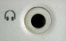
Some newer computers, such as Lenovo laptops, have 3.5 mm TRRS headset sockets, which are compatible with phone headsets and may be distinguished by a headset icon instead of the usual headphones or microphone icons. These are particularly used for Voice over IP.
Video

Equipment requiring video with stereo audio input/output sometimes uses 3.5 mm TRRS connectors. Two incompatible variants exist, of 15 millimetres (0.59 in) and 17 mm (0.67 in) length, and using the wrong variant may either simply not work, or could cause physical damage.
Attempting to fully insert the longer (17 mm) plug into a receptacle designed for the shorter (15 mm) plug may damage the receptacle, and may damage any electronics located immediately behind the receptacle. However, partially inserting the plug will work as the tip/ring/ring distances are the same for both variants.
Using the shorter plug in a socket designed for the longer connector will result in the plug not 'locking in', and may additionally result in wrong signal routing and/or a short circuit inside the equipment (e.g. the plug tip may cause the contacts inside the receptacle - tip/ring 1, etc. - to short together).
The shorter 15 mm TRRS variant is more common and fully physically compatible with 'standard' 3.5 mm TRS and TS connectors.
Recording equipment
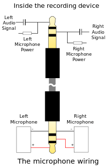
Many small video cameras, laptops, recorders and other consumer devices use a 3.5 mm microphone connector for attaching a (mono/stereo) microphone to the system. These fall into three categories:
- Devices that use an un-powered microphone: usually a cheap dynamic or piezoelectric microphone. The microphone generates its own voltage, and needs no power.
- Devices that use a self-powered microphone: usually a condenser microphone with internal battery-powered amplifier.
- Devices that use a "plug-in powered" microphone: an electret microphone containing an internal FET amplifier. These provide a good quality signal, in a very small microphone. However, the internal FET needs a DC power supply, which is provided as a bias voltage for an internal preamp transistor.
Plug-in power is supplied on the same line as the audio signal, using an RC filter. The DC bias voltage supplies the FET amplifier (at a low current), while the capacitor decouples the DC supply from the AC input to the recorder. Typically, V=1.5 V, R=1 kΩ, C=47 µF.
If a recorder provides plug-in power, and the microphone does not need it, everything will usually work ok, although the sound quality may be lower than expected. In the converse case (recorder provides no power; microphone needs power), no sound will be recorded. Neither misconfiguration will damage consumer hardware, but providing power when none is needed could destroy a broadcast-type microphone.
PDAs and mobile phones
Three- or four-conductor (TRS or TRRS) 2.5 mm and 3.5 mm sockets are common on cell phones, providing mono (three conductor) or stereo (four conductor) sound and a microphone input, together with signaling (e.g., push a button to answer a call). Three-conductor 2.5 mm connectors are particularly common on older phones, while four-conductor 3.5 mm connectors are more common on newer smartphones. These are used both for handsfree headsets (esp. mono audio plus mic, also stereo audio plus mic, plus signaling for call handling) and for (stereo) headphones (stereo audio, no mic). Wireless (connectorless) headsets or headphones usually use the Bluetooth protocol.
There is no recognised standard for TRRS connectors or compatibility with three conductor TRS. The four conductors of a TRRS connector are assigned to different purposes by different manufacturers. Any 3.5 mm plug can be plugged mechanically into any socket, but many combinations are electrically incompatible. For example, plugging TRRS headphones into a TRS headset socket (or the reverse), plugging TRS headphones or headsets into a TRRS socket, or plugging TRRS headphones or headsets from one manufacturer into a TRRS socket from another may not function correctly, or at all. Mono audio will usually work, but stereo audio or microphone may not work, depending on wiring. Signaling compatibility depends both on wiring compatibility and the signals sent by the hands-free/headphones controller being correctly interpreted by the phone. Adapters that are wired for headsets will not work for stereo headphones and conversely. Further, as TTY/TDDs are wired as headsets, TTY adapters can also be used to connect a 2.5 mm headset to a phone.
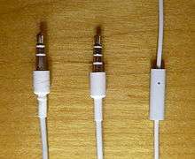
3.5 mm TRRS (stereo-plus-mic) sockets became particularly common on smartphones, and have been used e.g. by Nokia since 2006; they are often compatible with standard 3.5 mm stereo headphones. Two different forms are frequently found, both of which place left audio on the tip and right audio on the first ring (mirroring the configuration found on stereo connectors). Where they differ is in the placement of the microphone and return contacts. The first, which places the ground return on the second ring and the microphone on the sleeve, is used by Apple's iPhone line (With the iPhone 7, Apple has replaced the standard 3.5mm jack with their proprietary Lightning connector),[20] HTC devices, latest Samsung, Nokia and Sony phones, among others. The second, which reverses these contacts, is used by older Nokia mobiles, older Samsung smartphones and some Sony Ericsson phones.[21] There are adapters that swap the poles over to allow a device made to one standard to be used with a headset made to the other.[22]
Some computers now include a TRRS headset socket, compatible with headsets intended for smartphones. One such pin assignment, with ground on the sleeve, is standardized in OMTP[23] and has been accepted as a national Chinese standard YDT 1885-2009.
TRRS standards
| Standard | Tip | Ring 1 | Ring 2 | Sleeve | Devices using this standard |
|---|---|---|---|---|---|
| OMTP | Left audio | Right audio | Microphone | Ground | old Nokia (and also Lumia starting from the 2nd gen[24]), old Samsung (2012 Chromebooks), old Sony Ericsson (2010 and 2011 Xperias), Sony (PlayStation Vita), OnePlus One, Xbox One controller with head phone jack, iPhone sold in China[25] |
| CTIA / AHJ | Left audio | Right audio | Ground | Microphone | Apple, HTC, LG, Blackberry, latest Nokia (including 1st gen Lumia as well as later models), latest Samsung, Jolla, Sony (Dualshock 4), Microsoft (including Surface and Xbox One controller with chat adapter)[26] most Android phones |
| CTIA-Style AV[27] | Left audio | Right audio | Ground | CVBS video | Apple iPod (up to 6th Generation), Raspberry Pi (2014 onwards), Xbox 360 E, Zune, some mobile phones |
| Video/Audio 1 | Left audio | CVBS video | Ground | Right audio | Sony and Panasonic camcorders. On some early Sony camcorders, this socket doubled up as a headphone socket. When a headphone plug was inserted, Ring 2 was shorted to the sleve contact and the camcorder output the right audio on ring 1.[28] |
| Video/Audio 2 | CVBS video | Left audio | Right Audio | Ground | Unknown camcorders, portable VCD and DVD players, Western Digital TV live!, some newer LG TVs |
| Video/Audio 3 | CVBS video | Left audio | Ground | Right audio | Toshiba TVs |
- Notes:
- Nokia started to implement a universal audio connector, which enables the use of both American Headset Jack (AHJ) headsets and standard Nokia OMTP headsets.[29][30]
- The 4-pole 3.5 mm connector is defined by the Japanese standard JEITA/EIAJ RC-5325A, "4-Pole miniature concentric plugs and jacks", originally published in 1993.[31] 3-pole 3.5 mm TRS connectors are defined in JIS C 6560. See also JIS C 5401 and IEC 60130-8.
- A posting on All About Windows Phone provides more detail about the differences between the AHJ, OMTP, and Apple implementations, in covering the one earbud manufacturer's introduction of three separate models for each "standard".[32]
- The Android Wired Audio Headset Specification requires the CTIA pinout order (LRGM), "Except in regions with legal requirements for OMTP pinout". This document also describes the headset button actions, and these may be taken from the CTIA spec.[33]
- The article "Headset jacks on newer laptops" details how Linux can be configured to take these differences into account.[34]
- The USB Type-C Cable and Connector Specification Revision 1.1 specifies a mapping from a USB Type-C jack to a 4-pole TRRS jack, for the use of headsets, and supports both CTIA and OMTP (YD/T 1885-2009) modes. See Audio Adapter Accessory Mode (Appendix A).
- Third party suppliers of audio/video cables sell cables conforming to the Sony wiring and the Panasonic wiring. It is not clear why as they are both wired identically.
- This is a comprehensive description of many of the phone/laptop/etc. compatibility issues.[35]
- Semiconductor devices such as the Texas Instruments TS3A227E Autonomous Audio Accessory Detection and Configuration Switch[36] are available which can automatically reconfigure a 4-pole jack for several configurations. Integrating such devices into the equipment will allow almost any headset to be used and greatly reduce compatibility problems.
TRRRS standards
New TRRRS standard for 3.5mm connectors was developed and recently approved by ITU-T.[37] The new standard, called P.382 (former P.MMIC), outlines technical requirements and test methods for a 5 pole socket and plug configuration. Compared to legacy TRRS standard TRRRS provides one extra line that can be used for connecting a second microphone or external power to/from the audio accessory. P.382 requires compliant sockets and plugs to be backwards compatible with legacy TRRS and TRS connectors. Therefore P.382 compliant TRRRS connectors should allow for seamless integration when used on new products. TRRRS connectors enable following audio applications: active noise cancelling, binaural recording and others, where dual analogue microphone lines can be directly connected to a host device.
Aircraft headsets
Commercial and general aviation (GA) civil airplane headset plugs are similar, but not identical. A standard 1⁄4 in monaural plug, type PJ-055, is used for headphones, paired with special tip-ring-sleeve, 0.206 inch diameter plug, type PJ-068, for the microphone. On the microphone plug the Ring is used for the microphone 'hot' and the sleeve is common or microphone 'Lo'. The extra (tip) connection in the microphone plug is often left unconnected but is also sometimes used for various functions, most commonly an optional push-to-talk switch, but on some aircraft it carries headphone audio and on others a DC supply. On many newer GA aircraft the headphone jack is a standard 1⁄4 in phone connector wired in the standard unbalanced stereo configuration instead of the PJ-055 to allow stereo music sources to be reproduced.
Military aircraft and civil helicopters have another type termed a U-174/U. These are also termed 'NATO plugs' or Nexus TP120[38] telephone plugs. They are similar to 1⁄4 in (6.35 mm) plug, but with a 7.10 mm (0.280 in) diameter short shaft with an extra ring, i.e. four conductors in total, allowing two for the headphones (mono), and two for the microphone. There is a confusingly similar four pole (or four conductor) British connector with a slightly smaller diameter and a different wiring configuration used for headsets in many UK Military aircraft and often also referred to as a NATO or 'UK NATO' connector.
Switch contacts
Panel-mounting jacks are often provided with switch contacts. Most commonly, a mono jack is provided with one normally closed (NC) contact, which is connected to the tip (live) connection when no plug is in the socket, and disconnected when a plug is inserted. Stereo sockets commonly provide two such NC contacts, one for the tip (left channel live) and one for the ring or collar (right channel live). Some designs of jack also have such a connection on the sleeve. As this contact is usually ground, it is not much use for signal switching, but could be used to indicate to electronic circuitry that the socket was in use.
Less commonly, some jacks are provided with normally open (NO) or change-over contacts, and/or the switch contacts may be isolated from the connector.
The original purpose of these contacts was for switching in telephone exchanges, for which there were many patterns. Two sets of change-over contacts, isolated from the connector contacts, were common. The more recent pattern of one NC contact for each signal path, internally attached to the connector contact, stems from their use as headphone jacks. In many amplifiers and equipment containing them, such as electronic organs, a headphone jack is provided that disconnects the loudspeakers when in use. This is done by means of these switch contacts. In other equipment, a dummy load is provided when the headphones are not connected. This is also easily provided by means of these NC contacts.
Other uses for these contacts have been found. One is to interrupt a signal path to enable other circuitry to be inserted. This is done by using one NC contact of a stereo jack to connect the tip and ring together when no plug is inserted. The tip is then made the output, and the ring the input (or vice versa), thus forming a patch point.
Another use is to provide alternative mono or stereo output facilities on some guitars and electronic organs. This is achieved by using two mono jacks, one for left channel and one for right, and wiring the NC contact on the right channel jack to the tip of the other, to connect the two connector tips together when the right channel output is not in use. This then mixes the signals so that the left channel jack doubles as a mono output.
Where a 3.5 mm or 2.5 mm jack is used as a DC power inlet connector, a switch contact may be used to disconnect an internal battery whenever an external power supply is connected, to prevent incorrect recharging of the battery.
A standard stereo jack is used on most battery-powered guitar effects pedals to eliminate the need for a separate power switch. In this configuration, the internal battery has its negative terminal wired to the sleeve contact of the jack. When the user plugs in a two-conductor (mono) guitar or microphone lead, the resulting short-circuit between sleeve and ring connects an internal battery to the unit's circuitry, ensuring that it powers up or down automatically whenever a signal lead is inserted or removed. A drawback of this design is the risk of inadvertently discharging the battery if the lead is not removed after use, such as if the equipment is left plugged in overnight.
Design
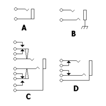
- A two-conductor TS phone connector. The connection to the sleeve is the rectangle towards the right, and the connection to the tip is the line with the notch. Wiring connections are illustrated as white circles.
- A three-conductor TRS phone connector. The upper connector is the tip, as it is farther away from the sleeve. The sleeve is shown connected directly to the chassis, a very common configuration. This is the typical configuration for a balanced connection. Some jacks have metal mounting connections (which would make this connection) and some have plastic, to isolate the sleeve from the chassis, and provide a separate sleeve connection point, as in A.
- This three-conductor jack has two isolated SPDT switches. They are activated by a plug going into the jack, which disconnects one throw and connects the other. The white arrowheads indicate a mechanical connection, while the black arrowheads indicate an electrical connection. This would be useful for a device that turns on when a plug is inserted, and off otherwise, with the power routed through the switches.
- This three-conductor jack has two normally closed switches connected to the contacts themselves. This would be useful for a patch point, for instance, or for allowing another signal to feed the line until a plug is inserted. The switches open when a plug is inserted. A common use for this style of connector is a stereo headphone jack that shuts off the default output (speakers) when the connector is plugged in.

- Sleeve: usually ground
- Ring: Right-hand channel for stereo signals, negative polarity for balanced mono signals, power supply for power-using mono signal sources
- Tip: Left-hand channel for stereo signals, positive polarity for balanced mono signals, signal line for unbalanced mono signals
- Insulating rings
| Unbalanced mono in/out | Unbalanced mono insert[40] | Balanced mono in/out[41] | Unbalanced stereo | |
|---|---|---|---|---|
| Tip | Signal | Send or return signal | Positive/hot | Left channel |
| Ring | Ground or no Connection | Return or send signal | Negative/cold | Right channel |
| Sleeve | Ground | |||
- Notes:
- The first version of the popular Mackie 1604 mixer, the CR1604, used a tip negative, ring positive jack wiring scheme on the main left and right outputs.[42][43]
- Whirlwind Line Balancer/Splitters do not use the sleeve as a conductor on their unbalanced 6.35 mm/ 1⁄4 in TRS phone input. Tip and ring are wired to the transformer's two terminals; the sleeve is not connected.[45]
Balanced audio
When a phone connector is used to make a balanced connection, the two active conductors are both used for a monaural signal. The ring, used for the right channel in stereo systems, is used instead for the inverting input. This is a common use in small audio mixing desks, where space is a premium and they offer a more compact alternative to XLR connectors. Another advantage offered by TRS phone connectors used for balanced microphone inputs is that a standard unbalanced signal lead using a TS phone jack can simply be plugged into such an input. The ring (right channel) contact then makes contact with the plug body, correctly grounding the inverting input.
A disadvantage of using phone connectors for balanced audio connections is that the ground mates last and the socket grounds the plug tip and ring when inserting or disconnecting the plug. This causes bursts of hum, cracks and pops and may stress some outputs as they will be short circuited briefly, or longer if the plug is left half in.
This problem does not occur when using the 'gauge B' (BPO) phone connector (PO 316)[46] which although it is of 0.25 in (6.3 mm) diameter has a smaller tip and a recessed ring so that the ground contact of the socket never touches the tip or ring of the plug. This type was designed for balanced audio use, being the original telephone 'switchboard' connector and is still common in broadcast, telecommunications and many professional audio applications where it is vital that permanent circuits being monitored (bridged) are not interrupted by the insertion or removal of connectors. This same tapered shape used in the 'gauge B' (BPO) plug can be seen also in aviation and military applications on various diameters of jack connector including the PJ-068 and 'bantam' plugs. The more common straight-sided profile used in domestic and commercial applications and discussed in most of this article is known as 'gauge A'.
XLR connectors used in much professional audio equipment mate the ground signal on pin 1 first.
Unbalanced audio
Phone connectors with three conductors are also commonly used as unbalanced audio patch points (or insert points, or simply inserts), with the output on many mixers found on the tip (left channel) and the input on the ring (right channel). This is often expressed as "tip send, ring return". Other mixers have unbalanced insert points with "ring send, tip return". One advantage of this system is that the switch contact within the panel socket, originally designed for other purposes, can be used to close the circuit when the patch point is not in use. An advantage of the tip send patch point is that if it is used as an output only, a 2-conductor mono phone plug correctly grounds the input. In the same fashion, use of a "tip return" insert style allows a mono phone plug to bring an unbalanced signal directly into the circuit, though in this case the output must be robust enough to withstand being grounded. Combining send and return functions via single 1⁄4 in TRS connectors in this way is seen in very many professional and semi-professional audio mixing desks, due to the halving of space needed for insert jack fields which would otherwise need two jacks, one for send and one for return. The tradeoff is that unbalanced signals are more prone to buzz, hum and outside interference.
In some three-conductor TRS phone inserts, the concept is extended by using specially designed phone jacks that will accept a mono phone plug partly inserted to the first click and will then connect the tip to the signal path without breaking it. Most standard phone connectors can also be used in this way with varying success, but neither the switch contact nor the tip contact can be relied upon unless the internal contacts have been designed with extra strength for holding the plug tip in place. Even with stronger contacts, an accidental mechanical movement of the inserted plug can interrupt signal within the circuit. For maximum reliability, any usage involving first click or half-click positions will instead rewire the plug to short tip and ring together and then insert this modified plug all the way into the jack.
The TRS tip return, ring send unbalanced insert configuration is mostly found on older mixers. This allowed for the insert jack to serve as a standard-wired mono line input that would bypass the mic preamp. However tip send has become the generally accepted standard for mixer inserts since the early-to-mid 1990s. The TRS ring send configuration is still found on some compressor sidechain input jacks such as the dbx 166XL.[47]
In some very compact equipment, 3.5 mm TRS phone connectors are used as patch points.
Some sound recording devices use a three-conductor phone connector as a mono microphone input, using the tip as the signal path and the ring to connect a standby switch on the microphone.
External links
References
- ↑ International Library of Technology: ... Principles of Telephony ... International Textbook Company, Scranton, PA. 1907.
- ↑ Robert McLeish (2005). Radio Production. Newnes. ISBN 0-240-51972-8.
- ↑ Standard Reference Designations for Electrical and Electronics Parts and Equipments: IEEE 200-1975 (Reaffirmed 1988): Section 4.1.5.3. IEEE and ANSI, New York, NY. 1975.
- ↑ Reference Designations for Electrical and Electronics Parts and Equipment: ASME Y14.44-2008 (Replaced IEEE 200-1975): Section 2.1.5.3. ASME, Fairfield, NJ. 2008.
- ↑ Gary D. Davis and Ralph Jones (1989). The Sound Reinforcement Handbook. Hal Leonard. ISBN 0-88188-900-8.
- ↑
- "Barrel - Audio Connectors". Digi-Key catalog.
- "Audio-Video Connectors". Mouser Electronics catalog.
- "Jacks & Plugs". Switchcraft catalog.
- "Definition of: mini-phone connector". PC Magazine Encyclopedia.
Also called a 3.5mm or 1/8" connector, it is a plug and socket widely used for analog audio signals in portable devices.
- "Mini Phone Plug Adapters". RAM Electronics online catalog.
(e.g.) 3.5mm female stereo mini phone jack to 1/4” male Stereo phone plug Adapter
- ↑
- Lewallen, Dale (1993). This Old PC. Ziff-Davis Press. p. 362. ISBN 9781562761080. Retrieved September 8, 2016.
Remember that sound cards use the smaller 1/8-inch mini-phono plug...
- "Connect your Mac to a home stereo, iPod, iPad, musical instruments, or speakers". Apple.com. Apple Inc. Retrieved September 8, 2016.
1/8-inch stereo mini-phono plug adapter.
- "Glossary". Monoprice. Retrieved September 8, 2016.
3.5mm Plug/Jack: Also referred to as a 1/8 inch, auxillary input, mini stereo, and mini phono.
- "Beckman Coulter Automatic Temperature Compensation (ATC) Probe" (PDF). Beckman Coulter. 2008. p. 1. Retrieved September 8, 2016.
The 3.5mm mini-phono plug connector of the ATC Probe plugs into the 3.5mm mini-phono jack on the pH meter.
- Divine, John (September 7, 2016). "Apple's iPhone 7 and its 10 Flashy Features Won't Move AAPL Stock". USNews.com. U.S. News & World Report. Retrieved September 8, 2016.
...instead of the headphone jack.... There will be a lightning-to-mini phono adapter included as well.
- Lewallen, Dale (1993). This Old PC. Ziff-Davis Press. p. 362. ISBN 9781562761080. Retrieved September 8, 2016.
- ↑ "All-right jack: Simple but effective plug-in has endured for more than a century". Retrieved 2016-09-11.
- ↑ "Sony history 1960s". Sony official website.
- ↑ Description of 3.5mm earphone jack in described model:
"Vintage Sony 1960'S EFM-117J Radio". WorthPoint. Retrieved 2016-01-25. - ↑ "Build a Data Cable for the Yaesu VX-6".
- ↑ "Switchcraft Z15J 1/4" High Power Speaker Jack". Full Compass. Retrieved October 24, 2011.
High power 2-conductor speaker jack carries 15A (continuous) audio speaker current levels.
- ↑ Gibson, Bill. (2007) The Ultimate Live Sound Operator's Handbook, p. 202. Hal Leonard Corporation. ISBN 1-4234-1971-5
- ↑ "Switchcraft Telephone Jack and Telephone Plug Mating Chart" (PDF).
- ↑ Ranjan Parekh; Ranjan (2006). Principles of Multimedia. Tata McGraw-Hill Education. pp. 225–. ISBN 978-0-07-058833-2.
- ↑ page 113 (PDF) boschsecurity.com Retrieved January 2016
- ↑ Balanced Balanced TRRS Connector on Future Hifiman IEMs (IEM=In Ear Monitors) head-fi.org. Retrieved 17 January 2016
- ↑ "Questions Answered 4: Optical Output on the Mac".
- ↑ "Audio input/output on Macbook computers.".
- ↑ "iPhone 7 - Technical Specifications". Apple. Retrieved 2016-10-09.
- ↑ "MEElectronics - P version headset earphone compatibility". Meelec.com. Retrieved 2013-07-14.
- ↑ Digital Silence (earphone manufacturer): explanation of TRRS connectors and availability of adapter.
- ↑ "Wired Analogue Audio" (PDF). Retrieved 2012-06-01.
- ↑ http://allaboutwindowsphone.com/flow/item/17561_Jays_AB_headset_for_Windows_Ph.php
- ↑ http://beterhans.blogspot.jp/2013/01/chinese-iphones-earphone-is-forced-to.html
- ↑ https://together.jolla.com/question/6716/headphone-nokia-n9-and-jolla/#post-id-6721
- ↑ http://www.cablechick.com.au/blog/understanding-trrs-and-audio-jacks/
- ↑ Sony and Panasonic camcorder service manuals
- ↑ FAQ - What type of wired headsets can I use with my Nokia Lumia phone? - "Nokia Lumia 820 and 920 support both American Headset Jack (AHJ) headsets and standard Nokia OMTP headsets."
- ↑ Jays AB headset for Windows Phone and a note on headset standards - "Nokia's Windows Phone 8 devices (Nokia Lumia 520, 521, 620, 720, 810, 820, 822, 920, 925, and 928) use a new universal connector, enabling the use of both AHJ and OMTP headsets."
- ↑ "EIAJ RC-5325A".
- ↑ "Jays AB headset for Windows Phone and a note on headset standards". allaboutwindowsphone
.com . External link in|publisher=(help) - ↑ "Android Wired Audio Headset Specification".
- ↑ "Headset jacks on newer laptops".
- ↑ "Wired Headsets: A Tutorial on Connectors, Cables & Pinouts".
- ↑ "TS3A227E Autonomous Audio Accessory Detection and Configuration Switch".
- ↑ Technical requirements and test methods for multi-microphone wired headset or headphone interfaces of digital wireless terminals
- ↑ "Item # TP-120, Telephone Plug". Amphenol Nexus Technologies, Inc. Retrieved 2012-01-12.
- ↑ "Jack Schematics table" (PDF).
- ↑ "Diagrams" (PDF). Retrieved 2012-05-28.
- ↑ "Frequently Asked Questions". Retrieved 2012-05-28.
- ↑ Sweetwater (2000-01-13). "Sweetwater inSync". Sweetwater.com. Retrieved 2013-07-14.
- ↑ "Silent Way's recording tricks- Mackie CR-1604 mixer". Silentway.com. Retrieved 2013-07-14.
- ↑ "QSC Audio Products. Frequently Asked Questions".
- ↑ Archived November 10, 2006, at the Wayback Machine.
- ↑ "Neutrik mil-b-gauge-type plugs".
- ↑ "dbx 166XL compressor with balanced TRS tip send input and output jacks and one TRS ring send sidechain jack".
External links
- The 19th Century plug that's still being used BBC
-
 Media related to TRS connector at Wikimedia Commons