USB On-The-Go
USB On-The-Go, often abbreviated to USB OTG or just OTG, is a specification first used in late 2001 that allows USB devices, such as digital audio players or mobile phones, to act as a host, allowing other USB devices, such as USB flash drives, digital cameras, mice or keyboards, to be attached to them. Use of USB OTG allows those devices to switch back and forth between the roles of host and device. For instance, a mobile phone may read from removable media as the host device, but present itself as a USB Mass Storage Device when connected to a host computer.
In other words, USB On-The-Go introduces the concept of a device performing both master and slave roles – whenever two USB devices are connected and one of them is a USB On-The-Go device, they establish a communication link. The device controlling the link is called the master or host, while the other is called the slave or peripheral.
Overview

Standard USB uses a master/slave architecture; a host acts as the master device for the entire bus, and a USB device acts as a slave. If implementing standard USB, devices must assume one role or the other, with computers generally set up as hosts, while (for example) printers normally function as slaves. In the absence of USB OTG, cell phones often implemented slave functionality to allow easy transfer of data to and from computers. Such phones, as slaves, could not readily be connected to printers as they also implemented the slave role. USB OTG directly addresses this issue.
When a device is plugged into the USB bus, the master device, or host, sets up communications with the device and handles service provisioning (the host's software enables or does the needed data-handling such as file managing or other desired kind of data communication or function). That allows the devices to be greatly simplified compared to the host; for example, a mouse contains very little logic and relies on the host to do almost all of the work. The host controls all data transfers over the bus, with the devices capable only of signalling (when polled) that they require attention. To transfer data between two devices, for example from a phone to a printer, the host first reads the data from one device, then writes it to the other.
While the master-slave arrangement works for some devices, many devices can act either as master or as slave depending on what else shares the bus. For instance, a computer printer is normally a slave device, but when a USB flash drive containing images is plugged into the printer's USB port with no computer present (or at least turned off), it would be useful for the printer to take on the role of host, allowing it to communicate with the flash drive directly and to print images from it.
USB On-The-Go recognizes that a device can perform both master and slave roles, and so subtly changes the terminology. With OTG, a device can be either a host when acting as a link master, or a "peripheral" when acting as a link slave. The choice between host and peripheral roles is handled entirely by which end of the cable the device is connected to. The device connected to the "A" end of the cable at start-up, known as the "A-device", acts as the default host, while the "B" end acts as the default peripheral, known as the "B-device".
After initial startup, setup for the bus operates as it does with the normal USB standard, with the A-device setting up the B-device and managing all communications. However, when the same A-device is plugged into another USB system or a dedicated host becomes available, it can become a slave.
USB On-The-Go does not preclude using a USB hub, but it describes host-peripheral role swapping only for the case of a one-to-one connection where two OTG devices are directly connected. Role swapping does not work through a standard hub, as one device will act as a host and the other as a peripheral until they are disconnected.
Specifications
USB OTG is a part of a supplement[1] to the Universal Serial Bus (USB) 2.0 specification originally agreed upon in late 2001 and later revised.[2] The latest version of the supplement also defines behavior for an Embedded Host which has targeted abilities and the same USB Standard-A port used by PCs.
SuperSpeed OTG devices, Embedded Hosts and peripherals are supported through the USB On-The-Go and Embedded Host Supplement[3] to the USB 3.0 specification.
Protocols
The USB On-The-Go and Embedded Host Supplement to the USB 2.0 specification introduced three new communication protocols:
- Attach Detection Protocol (ADP)
- Allows an OTG device, embedded host or USB device to determine attachment status in the absence of power on the USB bus, enabling both insertion-based behavior and the capability to display attachment status. It does so by periodically measuring the capacitance on the USB port to determine whether there is another device attached, a dangling cable, or no cable. When a large enough change in capacitance is detected to indicate device attachment, an A-device will provide power to the USB bus and look for device connection. At the same time, a B-device will generate SRP and wait for the USB bus to become powered.
- Session Request Protocol (SRP)
- Allows both communicating devices to control when the link's power session is active; in standard USB, only the host is capable of doing so. That allows fine control over the power consumption, which is very important for battery-operated devices such as cameras and mobile phones. The OTG or embedded host can leave the USB link unpowered until the peripheral (which can be an OTG or standard USB device) requires power. OTG and embedded hosts typically have little battery power to spare, so leaving the USB link unpowered helps in extending the battery runtime.
- Host Negotiation Protocol (HNP)
- Allows the two devices to exchange their host/peripheral roles, provided both are OTG dual-role devices. By using HNP for reversing host/peripheral roles, the USB OTG device is capable of acquiring control of data-transfer scheduling. Thus, any OTG device is capable of initiating data-transfer over USB OTG bus. The latest version of the supplement also introduced HNP polling, in which the host device periodically polls the peripheral during an active session to determine whether it wishes to become a host.
The main purpose of HNP is to accommodate users who have connected the A and B devices (see below) in the wrong direction for the task they want to perform. For example, a printer is connected as the A-device (host), but cannot function as the host for a particular camera, since it does not understand the camera's representation of print jobs. When that camera knows how to talk to the printer, the printer will use HNP to switch to the slave role, with the camera becoming the host so pictures stored on the camera can be printed out without reconnecting the cables. The new OTG protocols cannot pass through a standard USB hub since they are based on electrical signaling via a dedicated wire.
The USB On-The-Go and Embedded Host Supplement to the USB 3.0 specification introduces an additional protocol, Role Swap Protocol (RSP). This achieves the same purpose as HNP (i.e., role swapping) by extending standard mechanisms provided by the USB 3.0 specification. Products following the USB On-The-Go and Embedded Host Supplement to the USB 3.0 specification are also required to follow the USB 2.0 supplement in order to maintain backwards compatibility. SuperSpeed OTG devices (SS-OTG) are required to support RSP. SuperSpeed Peripheral Capable OTG devices (SSPC-OTG) are not required to support RSP since they can only operate at SuperSpeed as a peripheral; they have no SuperSpeed host and so can only role swap using HNP at USB 2.0 data rates.
Device roles
USB OTG defines two roles for devices: OTG A-device and OTG B-device, specifying which side supplies power to the link, and which initially is the host. The OTG A-device is a power supplier, and an OTG B-device is a power consumer. In the default link configuration, the A-device acts as a USB host with the B-device acting as a USB peripheral. The host and peripheral modes may be exchanged later by using HNP. Because every OTG controller supports both roles, they are often called "Dual-Role" controllers rather than "OTG controllers".
For integrated circuit (IC) designers, an attractive feature of USB OTG is the ability to achieve more USB capabilities with fewer gates.
A "traditional" approach includes four controllers, resulting in more gates to test and debug:
- USB high speed host controller based on EHCI (a register interface)
- Full/low speed host controller based on OHCI (another register interface)
- USB device controller, supporting both high and full speeds
- Fourth controller to switch the OTG root port between host and device controllers
Also, most gadgets must be either a host or a device. OTG hardware design merges all of the controllers into one dual-role controller that is somewhat more complex than an individual device controller.
Targeted peripheral list (TPL)
A manufacturer's targeted peripheral list (TPL) serves the aim of focusing a host device towards particular products or applications, rather than toward its functioning as a general-purpose host, as is the case for typical PCs. The TPL specifies products supported by the "targeting" host, defining what it needs to support, including the output power, transfer speeds, supported protocols, and device classes. It applies to all targeted hosts, including both OTG devices acting as a host and embedded hosts.
Plug
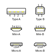
OTG mini plugs
The original USB On-The-Go standard introduced a plug receptacle called mini-AB that was replaced by micro-AB in later revisions (Revision 1.4 onwards). It could accept either a mini-A plug or a mini-B plug, while mini-A adapters allowed connection to standard-A USB cables coming from peripherals. The standard OTG cable had a mini-A plug on one end and a mini-B plug on the other end (it could not have two plugs of the same type).
The device with a mini-A plug inserted became an OTG A-device, and the device with a mini-B plug inserted became a B-device (see above). The type of plug inserted was detected by the state of the ID pin (the mini-A plug's ID pin was grounded, while the mini-B plug's was floating).
Pure mini-A plugs also existed, used where a compact host port was needed, but OTG was not supported.
OTG micro plugs
With the introduction of the USB micro plug, a new plug receptacle called micro-AB was also introduced. It can accept either a micro-A plug or a micro-B plug. Micro-A adapters allow for connection to standard-A plugs, as used on fixed or standard devices. An OTG product must have a single micro-AB receptacle and no other USB receptacles.[4][5]
An OTG cable has a micro-A plug on one end, and a micro-B plug on the other end (it cannot have two plugs of the same type). OTG adds a fifth pin to the standard USB connector, called the ID-pin; the micro-A plug has the ID pin grounded, while the ID in the micro-B plug is floating. A device with a micro-A plug inserted becomes an OTG A-device, and a device with a micro-B plug inserted becomes a B-device. The type of plug inserted is detected by the state of the pin ID.
Three additional ID pin states are defined[4] at the nominal resistance values of 124 kΩ, 68 kΩ, and 36.5 kΩ, with respect to the ground pin. These permit the device to work with USB Accessory Charger Adapters that allows the OTG device to be attached to both a charger and another device simultaneously.[6]
These three states are used in the cases of:
- A charger and either no device or an A-device that is not asserting VBUS (not providing power) are attached. The OTG device is allowed to charge and initiate SRP but not connect.[6]
- A charger and an A-device that is asserting VBUS (is providing power) are attached. The OTG device is allowed to charge and connect but not initiate SRP.[6]
- A charger and a B-device are attached. The OTG device is allowed to charge and enter host mode.[6]
USB 3.0 introduced a backwards compatible SuperSpeed extension of the micro-AB receptacle and micro-A and micro-B plugs. They contain all pins of the non-Superspeed micro connectors and use the ID pin to identify the A-device and B-device roles, also adding the SuperSpeed pins.
OTG micro cables

When attached to a PC, an OTG device requires a cable which has a USB Standard-A plug on one end and a micro-B plug on the other end. In order to attach a peripheral to an OTG device, the peripheral either needs a cable ending in a micro-A plug, which is inserted into the OTG device's micro-AB receptacle, or the OTG device itself needs an adapter cable with a micro-A plug on one end and a Standard-A receptacle on the other. The adapter cable enables any standard USB peripheral to be attached to an OTG device. Attaching two OTG devices together requires either a cable with a micro-B plug at one end and a micro-A plug at the other, or can be achieved using a combination of the PC cable and adapter cable.
Smartphone and tablet implementation
BlackBerry 10.2 implements Host Mode (like in the BlackBerry Z30 handset).[7] Nokia has implemented USB OTG in many of their Symbian cellphones such as Nokia N8, C6-01, C7, Oro, E6, E7, X7, 603, 700, 701 and 808 Pureview. Some high-end Android phones produced by HTC, and Sony under Xperia series also have it.[8] Samsung[9][10]
Android version 3.1 or newer supports USB On-The-Go, but not on all devices.[11][12]
Specifications listed on technology web sites (such as GSMArena, PDAdb.net, PhoneScoop, and others) can help determine compatibility. Using GSMArena as an example, one would locate the page for a given device, and examine the verbiage under Specifications → Comms → USB. If "USB Host" is shown, the device should be capable of supporting OTG-type external USB accessories.[13][14][15]
In many of the above implementations, the host device has only a micro-B receptacle rather than a micro-AB receptacle. Although non-standard, micro-B to micro-A receptacle adapters are widely available and used in place of the mandated micro-A receptacle on these devices.
Backward compatibility
USB OTG devices are backward-compatible with USB 2.0 (USB 3.0 for SuperSpeed OTG devices) and will behave as standard USB hosts or devices when connected to standard (non-OTG) USB devices. The main exception is that OTG hosts are only required to provide enough power for the products listed on the TPL, which may or may not be enough to connect to a peripheral that is not listed. A powered USB hub may sidestep the issue, if supported, since it will then provide its own power according to either the USB 2.0 or USB 3.0 specifications.
Some incompatibilities in both HNP and SRP were introduced between the 1.3 and 2.0 versions of the On-The-Go supplement, which can lead to interoperability issues when using those protocol versions.
Charger compatibility
Some devices can use their USB ports to charge built-in batteries, while other devices can detect a dedicated charger and draw more than 500 mA (0.5 A), allowing them to charge more rapidly. OTG devices are allowed to use either option.[6]
See also
References
- ↑ "On-The-Go and Embedded Host Supplement to the USB 2.0 Specification, Revision 2.0 plus ECN and errata". USB.org. July 14, 2011.
- ↑ Heise, Heinz. "USB-On-the-Go-Specification Settled". Heise.de.
- ↑ "On-The-Go and Embedded Host Supplement to the USB 3.0 Specification, Revision 1.0". USB.org. July 1, 2011.
- 1 2 "Universal Serial Bus Revision 2.0 specification". On-The-Go and Embedded Host Supplement to the USB Revision 2.0 Specification, Revision 2.0 version 1.1a. USB Implementers Forum, Inc. July 27, 2012. Retrieved 2013-04-21.
- ↑ "Universal Serial Bus Revision 2.0 specification". Universal Serial Bus Micro-USB Cables and Connectors Specification, Revision 1.01. USB Implementers Forum, Inc. 4 April 2007. Retrieved 2013-04-21.
- 1 2 3 4 5 "Battery Charging Specification". USB Implementers Forum, Inc. 15 April 2009. Retrieved 2009-09-23.
- ↑ KB34983-Support for USB Embedded Host mode on BlackBerry 10 OS version 10.2
- ↑ USB On the Go | HTC Blog
- ↑ Samsung Galaxy S II Able To Use Standard USB OTG Cable For USB On-The-Go Access | TalkAndroid.com
- ↑ Xperia S USB OTG demonstrated Video | Xperia Blog
- ↑ "Android Issue 738: I hope Android will implement and support the USB host feature". Google.com. 2008-05-30. Retrieved 2013-05-30.
- ↑ "USB Host – Android Developers". developer.android.com. 2013-05-30. Retrieved 2013-05-30.
- ↑ http://www.gsmarena.com/ GSMArena
- ↑ http://pdadb.net PDAdb.net
- ↑ http://www.phonescoop.com PhoneScoop
External links
- Official website
- "Tutorial 1822: USB On-The-Go Basics". Maxim Integrated. Dec 20, 2002.
Abstract: USB On-the-Go (OTG) allows two USB devices to talk to each other without requiring the services of a personal computer ... Part of the magic of OTG is that a host and peripheral can exchange roles if necessary.
- "USB OTG Flash Drives". Kingston.
- Broida, Rick (Feb 5, 2014). "How to tell if your Android phone or tablet supports USB On-The-Go". CNet.
Refers to two apps, to verify OTG compatibility, and to overcome (root) and enable OTG
- "USB OTG in a pocket friendly cubic device". Giftick.