IEEE-488
IEEE-488 is a short-range digital communications 8-bit parallel multi-master interface bus specification. IEEE-488 was created as HP-IB (Hewlett-Packard Interface Bus) and is commonly called GPIB (General Purpose Interface Bus). It has been the subject of several standards.
Although originally created in the late 1960s to connect together automated test equipment, it also had some success during the 1970s and 1980s as a peripheral bus for early microcomputers, notably the Commodore PET. Newer standards have largely replaced IEEE-488 for computer use, but it still sees some use in the test equipment field.
Origins
In the late 1960s, Hewlett-Packard (HP)[1] manufactured various automated test and measurement instruments, such as digital multimeters and logic analyzers. They developed the HP Interface Bus (HP-IB) to enable easier interconnection between instruments and controllers (computers and other instruments).
The bus was relatively easy to implement using the technology at the time, using a simple parallel bus and several individual control lines. For example, the HP 59501 Power Supply Programmer and HP 59306A Relay Actuator were both relatively simple HP-IB peripherals implemented only in TTL, using no microprocessor.
HP licensed the HP-IB patents for a nominal fee to other manufacturers. It became known as the General Purpose Interface Bus (GPIB), and became a de facto standard for automated and industrial instrument control. As GPIB became popular, it was formalized by various standards organizations.
Standards
In 1975, the IEEE standardized the bus as Standard Digital Interface for Programmable Instrumentation, IEEE-488; it was revised in 1978 (producing IEEE-488-1978).[2] The standard was revised in 1987, and redesignated as IEEE-488.1 (IEEE-488.1-1987). These standards formalized the mechanical, electrical, and basic protocol parameters of GPIB, but said nothing about the format of commands or data.
In 1987, IEEE introduced Standard Codes, Formats, Protocols, and Common Commands, IEEE-488.2. It was revised in 1992.[3] IEEE-488.2 provided for basic syntax and format conventions, as well as device-independent commands, data structures, error protocols, and the like. IEEE-488.2 built on IEEE-488.1 without superseding it; equipment can conform to IEEE-488.1 without following IEEE-488.2.
While IEEE-488.1 defined the hardware and IEEE-488.2 defined the protocol, there was still no standard for instrument-specific commands. Commands to control the same class of instrument, e.g., multimeters, would vary between manufacturers and even models.
The United States Air Force,[4] and later Hewlett-Packard, recognized this problem. In 1989, HP developed their TML language[5] which was the forerunner to Standard Commands for Programmable Instrumentation (SCPI). SCPI was introduced as an industry standard in 1990.[6] SCPI added standard generic commands, and a series of instrument classes with corresponding class-specific commands. SCPI mandated the IEEE-488.2 syntax, but allowed other (non-IEEE-488.1) physical transports.
The IEC developed their own standards in parallel with the IEEE, with IEC-60625-1 and IEC-60625-2, later replaced by IEC-60488.
National Instruments introduced a backward-compatible extension to IEEE-488.1, originally known as HS-488. It increased the maximum data rate to 8 Mbyte/s, although the rate decreases as more devices are connected to the bus. This was incorporated into the standard in 2003 (IEEE-488.1-2003),[7] over HP's objections.[8][9]
In 2004, the IEEE and IEC combined their respective standards into a "Dual Logo" IEEE/IEC standard IEC-60488-1, Standard for Higher Performance Protocol for the Standard Digital Interface for Programmable Instrumentation - Part 1: General,[10] replaces IEEE-488.1/IEC-60625-1, and IEC-60488-2,Part 2: Codes, Formats, Protocols and Common Commands,[11] replaces IEEE-488.2/IEC-60625-2.[12]
Characteristics
IEEE-488 is an 8-bit, electrically parallel bus. The bus employs sixteen signal lines — eight used for bi-directional data transfer, three for handshake, and five for bus management — plus eight ground return lines.
Every device on the bus has a unique 5-bit primary address, in the range from 0 to 30 (31 total possible addresses).[13][14]
The standard allows up to 15 devices to share a single physical bus of up to 20 meters total cable length. The physical topology can be linear or star (forked).[15] Active extenders allow longer buses, with up to 31 devices theoretically possible on a logical bus.
Control and data transfer functions are logically separated; a controller can address one device as a “talker” and one or more devices as “listeners” without having to participate in the data transfer. It is possible for multiple controllers to share the same bus; but only one can be the "Controller In Charge" at a time.[16]
In the original protocol, transfers use an interlocked, three-wire ready–valid–accepted handshake.[17] The maximum data rate is about one megabyte per second. The later HS-488 extension relaxes the handshake requirements, allowing up to 8 Mbyte/s. The slowest participating device determines the speed of the bus.[18]
Connectors
| Pin out | |||
|---|---|---|---|
 | |||
| Female IEEE-488 connector | |||
| Pin 1 | DIO1 | Data input/output bit. | |
| Pin 2 | DIO2 | Data input/output bit. | |
| Pin 3 | DIO3 | Data input/output bit. | |
| Pin 4 | DIO4 | Data input/output bit. | |
| Pin 5 | EOI | End-or-identify. | |
| Pin 6 | DAV | Data valid. | |
| Pin 7 | NRFD | Not ready for data. | |
| Pin 8 | NDAC | Not data accepted. | |
| Pin 9 | IFC | Interface clear. | |
| Pin 10 | SRQ | Service request. | |
| Pin 11 | ATN | Attention. | |
| Pin 12 | SHIELD | ||
| Pin 13 | DIO5 | Data input/output bit. | |
| Pin 14 | DIO6 | Data input/output bit. | |
| Pin 15 | DIO7 | Data input/output bit. | |
| Pin 16 | DIO8 | Data input/output bit. | |
| Pin 17 | REN | Remote enable. | |
| Pin 18 | GND | (wire twisted with DAV) | |
| Pin 19 | GND | (wire twisted with NRFD) | |
| Pin 20 | GND | (wire twisted with NDAC) | |
| Pin 21 | GND | (wire twisted with IFC) | |
| Pin 22 | GND | (wire twisted with SRQ) | |
| Pin 23 | GND | (wire twisted with ATN) | |
| Pin 24 | Logic ground | ||
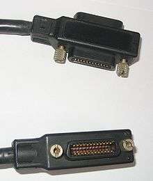
IEEE-488 specifies a 24-pin Amphenol-designed micro ribbon connector. Micro ribbon connectors have a D-shaped metal shell, but are larger than D-subminiature connectors. They are sometimes called "Centronics connectors" after the 36-pin micro ribbon connector Centronics used for their printers.
One unusual feature of IEEE-488 connectors is they commonly use a "double-headed" design, with male on one side, and female on the other. This allows stacking connectors for easy daisy-chaining. Mechanical considerations limit the number of stacked connectors to four or fewer, although a workaround involving physically supporting the connectors may be able to get around this.
They are held in place by screws, either UTS (now largely obsolete) or metric M3.5×0.6 threads. Early versions of the standard suggested that metric screws should be blackened to avoid confusion with the incompatible UTS threads. However, by the 1987 revision this was no longer considered necessary because of the prevalence of metric threads.[19]
The IEC-60625 standard prescribes the use of 25-pin D-subminiature connectors (the same as used for the parallel port on IBM-PCs). This connector did not gain significant market acceptance against the established 24-pin connector.
Capabilities
| Function | Abbreviation | Description / Example |
|---|---|---|
| Source Handshake | SH | SH1 - complete |
| Acceptor Handshake | AH | AH1 - complete |
| Basic Talker | T | T5 - responds to serial poll; untalks when listen address received; talk only capability T6 - untalks when listen address received; no talk only T7 - no serial poll; untalks when listen address received; talk only capability |
| Extended Talker | TE | TE0 - no extended talker |
| Basic Listener | L | L3 - Listen only mode; unlistens if talk address received L4 - Unlistens if talk address received |
| Extended Listener | LE | LE0 - no extended listener |
| Service Request | SR | SR0 - no service request capability SR1 - complete |
| Remote-Local | RL | RL0 - no local lockout RL1 - complete |
| Parallel Poll | PP | PP0 - does not respond to Parallel Poll |
| Device Clear | DC | DC1 - complete |
| Device Trigger | DT | DT0 - no device trigger capability DT1 - complete |
| Controller | C | C0 - no controller function |
| E | E1 - open collector drive electronics E2 - three state drivers |
More information see Tektronix.[20]
Use as a computer interface
HP's designers did not specifically plan for IEEE-488 to be a peripheral interface for general-purpose computers; the focus was on instrumentation. But when HP's early microcomputers needed an interface for peripherals (disk drives, tape drives, printers, plotters, etc.), HP-IB was readily available and easily adapted to the purpose.
HP computer products which used HP-IB included the HP series 80, HP 9800 series,[21] the HP 2100 series,[22] and the HP 3000 series.[23] HP computer peripherals which did not utilize the RS-232 communication interface often used HP-IB including disc systems like the HP 7935. Some of HP's advanced pocket calculators of the 1980s, such as the HP-41 and HP-71B series, also had IEEE-488 capabilities, via an optional HP-IL/HP-IB interface module.
Other manufacturers adopted GPIB for their computers as well, such as with the Tektronix 405x line.
The Commodore PET (introduced 1977) range of personal computers connected their peripherals using the IEEE-488 bus, but with a non-standard card edge connector. Commodore's following 8-bit machines utilized a serial bus whose protocol was based on IEEE-488.[24] Commodore marketed an IEEE-488 cartridge for the VIC-20 [25] but never produced a cartridge for the Commodore 64. Several third party suppliers of Commodore 64 peripherals made a cartridge for the C64 that provided an IEEE-488-derived interface on a card edge connector similar to that of the PET series.[26]
Eventually, faster, more complete standards such as SCSI superseded IEEE-488 for peripheral access.
|
.jpg)

Comparison with other interface standards
Electrically, IEEE-488 used a hardware interface that could be implemented with some discrete logic or with a microcontroller. The hardware interface enabled devices made by different manufacturers to communicate with a single host. Since each device generated the asynchronous handshaking signals required by the bus protocol, slow and fast devices could be mixed on one bus. The data transfer is relatively slow, so transmission line issues such as impedance matching and line termination are ignored. There was no requirement for galvanic isolation between the bus and devices, which created the possibility of ground loops causing extra noise and loss of data.
Physically, the IEEE-488 connectors and cabling were rugged and held in place by screws. While physically large and sturdy connectors were an advantage in industrial or laboratory set ups, the size and cost of the connectors was a liability in applications such as personal computers.
Although the electrical and physical interfaces were well defined, there was not an initial standard command set. Devices from different manufacturers might use different commands for the same function.[27] Some aspects of the command protocol standards were not standardized until Standard Commands for Programmable Instruments (SCPI) in 1990. Implementation options (e.g. end of transmission handling) can complicate interoperability in pre-IEEE-488.2 devices.
More recent standards such as USB, FireWire, and Ethernet take advantage of declining costs of interface electronics to implement more complex standards providing higher bandwidth. The multi-conductor (parallel data) connectors and shielded cable were inherently more costly than the connectors and cabling that could be used with serial data transfer standards such as RS-232, RS-485, USB, FireWire or Ethernet. Very few mass-market personal computers or peripherals (such as printers or scanners) implemented IEEE-488.
See also
| Wikimedia Commons has media related to IEEE 488. |
- Standard Commands for Programmable Instruments (SCPI)
- PCI eXtensions for Instrumentation (PXI)
- LAN eXtensions for Instrumentation (LXI)
- Virtual Instrument Software Architecture (VISA)
- HP series 80
- Rocky Mountain BASIC
- CBM-bus, a proprietary serial version of IEEE-488 by Commodore
References
- ↑ This part of HP was later (c. 1999) spun off as Agilent Technologies, and in 2014 Agilent's test and measurement division was spun off as Keysight Technologies.
- ↑ IEEE Standard Digital Interface for Programmable Instrumentation, Institute of Electrical and Electronics Engineers, 1987, ISBN 0-471-62222-2, ANSI/IEEE Std 488.1-1987, p. iii
- ↑ IEEE Standard Codes, Formats, Protocols, and Common Commands for Use With IEEE Std 488.1-1987, IEEE Standard Digital Interface for Programmable Instrumentation, Institute of Electrical and Electronics Engineers, 1992, ISBN 1-55937-238-9, IEEE Std 488.2-1992
- ↑ Project Mate in 1985
- ↑ "GPIB 101, A Tutorial of the GPIB Bus". ICS Electronics. p. 5, paragraph=SCPI Commands.
- ↑ "History of GPIB". National Instruments. Retrieved 2010-02-06.
In 1990, the IEEE 488.2 specification included the Standard Commands for Programmable Instrumentation (SCPI) document.
- ↑ "Upgraded Standard Boosts Speed of IEEE 488 Instrument Buses Eightfold". IEEE. 6 October 2003. Retrieved 2010-02-06.
- ↑ "HP and Other Test and Measurement Companies Urge IEEE to Oppose Revisions of Established IEEE-488 Standard" (Press release). Hewlett-Packard Company. December 1997. Archived from the original on June 10, 2011. Retrieved 2010-02-16.
- ↑ "P488.1 Project Home". IEEE. Archived from the original on April 28, 2010. Retrieved 2010-02-16.
- ↑ "IEC/IEEE Standard for Higher Performance Protocol for the Standard Digital Interface for Programmable Instrumentation - Part 1: General (Adoption of IEEE Std 488.1-2003)". IEEE. Retrieved 2010-02-06.
- ↑ "Standard Digital Interface for Programmable Instrumentation- Part 2: Codes, Formats, Protocols and Common Commands (Adoption of (IEEE Std 488.2-1992)". IEEE. Retrieved 2010-02-06.
- ↑ "Replaced or Withdrawn Publications". IEC. Retrieved 2010-02-06.
- ↑ "GPIB Addressing". NI-488.2 User Manual (PDF). National Instruments Corporation. February 2005. p. A-2. NI P/N 370428C-01. Retrieved 2010-02-16.
The primary address is a number in the range 0 to 30.
- ↑ "Table 1-1: 82350 GPIB interface card configuration parameters". Agilent 82350B PCI GPIB Interface: Installation and Configuration Guide (PDF). Agilent Technologies. 20 July 2009. p. 26. Agilent P/N 82350-90004. Retrieved 2010-02-16.
any address in the range 0 - 30, inclusive, may be used
- ↑ "GPIB Instrument Control Tutorial". National Instruments. 24 August 2009. Retrieved 2010-02-16.
connected in either a daisy-chain or star topology
- ↑ NI-488.2 User Manual (PDF). National Instruments Corporation. February 2005. p. A-1. NI P/N 370428C-01. Retrieved 2010-02-16.
- ↑ "Handshake Lines". NI-488.2 User Manual (PDF). National Instruments Corporation. February 2005. p. A-3. NI P/N 370428C-01. Retrieved 2010-02-16.
- ↑ "Using HS488 to Improve GPIB System Performance". National Instruments Corporation. 30 March 2009. Retrieved 2010-02-16.
- ↑ IEEE Standard Digital Interface for Programmable Instrumentation, Institute of Electrical and Electronics Engineers, 1987, p. v, ISBN 0-471-62222-2, ANSI/IEEE Std 488.1-1987,
The "helpful note" on metric threads found in previous editions has been deleted since metric thread use is common IEEE 488 practice. Consequently, the recommendation to coat such parts in black material to call attention to metric threads is also considered unnecessary.
- ↑ Tilden, Mark D. (1983), "Appendix A: Subsets Describe Interface Functions", 4041 GPIB Programming Guide (PDF), Tektronix, Inc., pp. 113–115
- ↑ "HP 98135A HP-IB Interface 9815". HP Computer Museum. Retrieved 2010-02-06.
- ↑ "59310A HP-IB Interface". HP Computer Museum. Retrieved 2010-02-06.
HP-IB interface for HP1000 and HP2000 computers
- ↑ "27113A HP-IB Interface". HP Computer Museum. Retrieved 2010-02-06.
CIO HP-IB interface for 3000 Series 900
- ↑ Bagnall, Brian (2006). On the Edge: The Spectacular Rise and Fall of Commodore, Variant Press. Page 221. ISBN 0-9738649-0-7
- ↑ Commodore drawing for VIC-1112 - Drawing no. 1110010 Rev:A
- ↑ http://www.zimmers.net/anonftp/pub/cbm/schematics/cartridges/c64/ieee-488/index.html Link to schematic for one such converter.
- ↑ Early devices might respond to an
IDcommand with an identification string; later standards had devices respond to the*IDcommand.
External links
- IEC-60488-1: Higher performance protocol for the standard digital interface for programmable instrumentation. Part 1: General. International Electrotechnical Commission. 15 July 2004.
- IEC-60488-2: Standard digital interface for programmable instrumentation. Part 2: Codes, formats, protocols and common commands. International Electrotechnical Commission. 7 May 2004.
- GPIB / IEEE 488 multiple page tutorial
| General | |
|---|---|
| Standards |
|
| Storage | |
| Peripheral | |
| Audio | |
| Portable | |
| Embedded | |
Interfaces are listed by their speed in the (roughly) ascending order, so the interface at the end of each section should be the fastest. | |