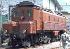
SBB-CFF-FFS Ce 6/8 I
 | |||||||||||||||||||||||||||||||||
| |||||||||||||||||||||||||||||||||
| |||||||||||||||||||||||||||||||||
| |||||||||||||||||||||||||||||||||
The Ce 6/8 I 14201 was one of four test locomotives ordered by the Schweizerischen Bundesbahnen (Swiss Federal Railways) (SBB) in June 1917. For gaining experience for ordering electrical locomotives this locomotive should – as her three sisters Be 3/5 12201, Be 4/6 12301 and Be 4/6 12302 – have been used for services on the Gotthardbahn (Gotthard railway). The development of freight locomotives subsequently took a complete different way which was not conceivable at the ordering date (see Ce 6/8II). The Ce 6/8I came into service only after the first Ce 6/8II.
History
In November 1913 the executive board of the Schweizerischen Bundesbahnen (Swiss Federal Railways) (SBB) decided to electrify Gotthardbahn (Gotthard railway) from Erstfeld to Biasca. Due to World War One the SBB had to reduce schedules more and more because shortage of coal. Therefore, – in autumn 1918 – on Sundays only milk trains were running.
That's why the SBB forced – beside other important lines – the electrification of the Gotthard railway line. This electrification was completed 1920.
For the traction on those lines the SBB urgently needed passenger- and freight locomotives.
Requirement specifications
The SBB demanded from the industry the compliance with the subseduent requirements:
- Weight per running meter of maximum 7 t/m
- Maximum axle load of 18 t, later – after adaptation of the infrastructure – 20 t
- Haulage of towed load of 430 t at a gradient of 26 ‰ with 35 km/h
- Reliable run-up with this load at a gradient of 26 ‰ and acceleration to 35 km/h within 4 minutes
- Two outward und return journeys Arth-Goldau – Chiasso within 28 hours (780 km)
- Electrical brake for deceleration of the locomotive weight at slopes
- Overload of 20% during 15 minutes without damages
Commissioning and proposal
The contract was awarded as follows:
- BBC: Design and construction of the freight locomotive
Schweizerische Lokomotiv- und Maschinenfabrik (SLM): Mechanical part.
Beside the compliance with the requirements specifications the designers got big freedom in the work out of their designs.
Delivery date
The locomotive was delivered at 7 July 1919. The scheduled services started only in December 1919 (nota bene one week after the first Ce 6/8II Crocodile was delivered).
Technical details
The mechanical part
Running gear
The running gear consisted of two bogies. In both bogies three drive-axles and a jackshaft were installed. The center drive-wheel had a side play of 2x25 mm. At the outer side of each bogie an idle-axle was mounted. This idle-axle was designed as an Adams axle and had a side-play of 2x31 mm relative to the bogie. Small cabinets were mounted on the outer part of the bogie frames.
Transmission of tractive force
The tractive force was transmitted from the drive-axles to the bogies. From there the force was carried over to the bogie-mounted towing hook and the buffers. In between the bogies were connected with a spring-loaded coupling similar to the tender coupling at steam locomotives. The locomotive body was not engaged in the transmission of tractive force.
Drive
Two motors were mounted in each bogie frame. They were located between the second and third drive-axle. The motors drove big cogwheels in the jackshaft over spring-loaded sprockets. The crank pin of the jackshaft drove over inclined connecting rod a pin mounted on the of the triangle-shaped coupling rod which connected the first and the second drive-axle. This pin was located close to the crank pin of the first drive-axle. A second coupling rod connected the second and the third drive-axles. This drive is known as Winterthurer Schrägstangenantrieb (Winterthur drive with inclined connecting rod).
Locomotive body
The locomotive body consisted of single bridging slab. On this slab the body parts were fixed with screws. The bridging slab laid on the bogies using pivot bearings. To prevent the transmission of tractive forces over the body the bearings had longitudinal play. Beside these two spring-loaded bearings were mounted. The locomotive body was almost identical to the one of the Be 4/6 12302.
Braking equipment
The automatic Westinghouse air brake and the locomotive brake acted in both bogies to both sides of the driving wheels of each drive-axle. The idle-wheels did not have brakes. Each cab was equipped with a handbrake which acted to the respective bogie.
Electrical part
Primary circuit
Two diamond-shaped pantographs – controllable with a valve in each cab – led the current from the catenary to the two main knife switches on the roof of the locomotive body. From these main knife switches the current was transferred to the Earthing knife switch. This was then led to the oil-cooled transformer over a lightning protection inductor and the oil-propelled main switch. The transformer was located in the center of the locomotive body. The huge lightning protection inductor was removed later since the practical experience showed that it was not necessary.
The cooling of the oil of the transformer occurred over a tube systems on both sides of the locomotive body by the use of an oil pump. These tubes were cooled by the air flow and the fan apertures in the body behind the tubes. These tubes were the main part of the very distinctive appearance of the locomotive as the Be 4/6 12302 and their successors Be 4/6 12303-12342.
The stepping switch transmitted the traction current to the motors which were connected in series circuit. The flat track stepping switch was mounted to the transformer. It consisted of 18 steps with voltages between 230 V and 1300 V. For both motor groups a reverse switch was mounted.
Auxiliary systems
The subsequent listed auxiliary systems were fed from the lowest tap of the transformer over a main fuse:
- two compressors
- one motor-generator for battery charging
- cab heating
- foot heating plate
- fan groups for the motors
- one oil pump for the circulation of the transformer cooling oil
- oil heating plate in cab I
The train heating system was powered directly from the transformer with 1000 V over an electro-pneumatical hopper.
The control and lighting circuits were fed from the batteries with 36 V DC. The motor-generator for battery charging was mounted in the cabinet II.
Electrical brake
The locomotive was designed first with six drive-axles. Because of the weight limit it was not possible to install an electrical brake. However, for the long steep slopes such a brake would have been beneficial.
But shortly after the first runs a regenerative brake was installed 1920 and – at the beginning only with two motors – tested between Kandersteg und Frutigen on the Lötschbergbahn. The outcome was encouraging. The equipment was then completed for service on the Gotthardbahn (Gotthard railway).
The principle was as follows: A rotating phase converter fed the stators of the motors. In this way the activated rotors fed back the current through the transformer to the catenary.
The brake was extremely efficient. It was possible to hold 300 t at 26 ‰ in steady conditions. But the design was complicated and the operation was difficult. As a result, huge flashovers occurred from time to time. Several explosions in the main switch occurred too. Therefore, the equipment was removed in 1931.
Multiple-unit control
The locomotive was not equipped with a multiple-unit control.
Service
The Ce 6/8I started with scheduled services at December 1919. She led freight and commuter trains between Bern and Spiez.
20 January 1920 the SBB commissioned the locomotive. From March 1920 until October 1920 the regenerative brake was tested between Kandersteg und Frutigen.
As Ce 6/8I 14201 she continued the scheduled service at 18 October 1920. The trips never went further than to Spiez. March 1921 the locomotive was relocated to the Gotthard.
The Ce 6/8I started her scheduled service almost at the same time as the first [[SBB-CFF-FFS Ce 6/8<sup>II</sup>|Ce 6/8II]]. The second one followed short time after. There was nothing more to test anymore than the regenerative brake. Therefore, the denotation «prototype» – even used sometimes in the technical literature – was wrong since the design of the [[SBB-CFF-FFS Ce 6/8<sup>II</sup>|Ce 6/8II]] was completely new.
At the beginning the locomotive started her services from the depot of Erstfeld. She was jointly scheduled in services with the Ce 6/8II. From 1925 until 1930 she was assigned to the depot of Biasca. Her duties were boost services ahead of trains between Biasca and Airolo at the southern end of the Gotthard rail tunnel. For this services the regenerative brake was a big advantage. With this brake the locomotive was able to return single to Biasca.
After the removal of the regenerative brake the locomotive returned 1931 to Erstfeld. 1938 she was relocated to the depot of Basle. There she was leading miscellaneous freight trains. The locomotive drivers did not like the quite poor running characteristics. On the other hand, they had to admit that they liked the high tractive force at lower speeds.
1961 two motors were damaged heavily. Since the EXPO 64 (Swiss National Exhibition/Schweizerische Landesausstellung) was very close it was decided to re-coil the defective motors. During this repairing action the locomotive was used in the Ticino canton. The two defective motors were replaced by ballast weights. Subsequently, the two motors were mounted again and the two others were revised.
After this action the performance of the locomotive was still very remarkable:
- 1963: 101,000 km
- 1964 (EXPO-Jahr): 65,000 km
Later the performance decreased rapidly:
- 1965: 19,000 km
- 1966: 4,000 km
At the end of her career the locomotive was used up to 1982 test locomotive for brake tests. She was the handed over to the Verkehrshaus der Schweiz. Together with the locomotives of the test operation between Seebach – Wettingen she represents the initiation of the electric traction. At that moment the locomotive had covered a distance of 2,500,000 km.
References
- Schneeberger, Hans (1995). Die elektrischen und Dieseltriebfahrzeuge der SBB, Band I: Baujahre 1904–1955 (in German). Luzern: Minirex AG. ISBN 3-907014-07-3.
- Jeanmaire, Claude. Die elektrischen und Diesel-Triebfahrzeuge schweizerischer Eisenbahnen, Die Lokomotiven der Schweizerischen Bundesbahnen (SBB) (in German). ISBN 3-85649-036-1.
| Wikimedia Commons has media related to SBB Ce 6/8 I. |
| SBB-CFF-FFS |
|  | ||||||||||||||||||||||||||
|---|---|---|---|---|---|---|---|---|---|---|---|---|---|---|---|---|---|---|---|---|---|---|---|---|---|---|---|---|
see also Category:Locomotives of Switzerland, Swiss locomotive and railcar classification | ||||||||||||||||||||||||||||