Regenerative brake


A regenerative brake is an energy recovery mechanism which slows a vehicle or object by converting its kinetic energy into a form which can be either used immediately or stored until needed. This contrasts with conventional braking systems, where the excess kinetic energy is converted to unwanted and wasted heat by friction in the brakes. In addition to improving the overall efficiency of the vehicle, regeneration can greatly extend the life of the braking system as its parts do not wear as quickly.
General
The most common form of regenerative brake involves an electric motor as an electric generator. In electric railways the electricity generated is fed back into the supply system. In battery electric and hybrid electric vehicles, the energy is stored chemically in a battery, electrically in a bank of capacitors, or mechanically in a rotating flywheel. Hydraulic hybrid vehicles use hydraulic motors to store energy in the form of compressed air.
Practical regenerative braking
Regenerative braking is not by itself sufficient as the sole means of safely bringing a vehicle to a standstill, or slowing it as required so it must be used in conjunction with another braking system such as friction-based braking.
- The regenerative braking effect drops off at lower speeds, and cannot bring a vehicle to a complete halt reasonably quickly.
- A regenerative brake does not immobilise a stationary vehicle; physical locking is required, for example to prevent vehicles from rolling down hills.
- Many road vehicles with regenerative braking do not have drive motors on all wheels (as in a two-wheel drive car); regenerative braking is normally only applicable to wheels with motors. For safety, the ability to brake all wheels is required.
- The regenerative braking effect available is limited, and insufficient in many cases, particularly in emergency situations.
- The friction brake is a necessary back-up in the event of failure of the regenerative brake.
Regenerative and friction braking must both be used, creating the need to control them to produce the required total braking. The GM EV-1 was the first commercial car to do this. In 1997 and 1998 engineers Abraham Farag and Loren Majersik were issued two patents for this brake-by-wire technology.[1][2]
Early applications commonly suffered from a serious safety hazard: in many early electric vehicles with regenerative braking, the same controller positions were used to apply power and to apply the regenerative brake, with the functions being swapped by a separate manual switch. This led to a number of serious accidents when drivers accidentally accelerated when intending to brake, such as the runaway train accident in Wädenswil, Switzerland in 1948, which killed twenty-one people.
Conversion to electric energy: the motor as a generator
.jpg)
Electric motors, when used in reverse function as generators, convert mechanical energy into electrical energy. Vehicles propelled by electric motors use them as generators when using regenerative braking, braking by transferring mechanical energy from the wheels to an electrical load.
Early examples of this system were the front-wheel drive conversions of horse-drawn cabs by Louis Antoine Krieger in Paris in the 1890s. The Krieger electric landaulet had a drive motor in each front wheel with a second set of parallel windings (bifilar coil) for regenerative braking.[3] In England, the Raworth system of "regenerative control" was introduced by tramway operators in the early 1900s, since it offered them economic and operational benefits as explained by A. Raworth of Leeds in some detail.[4][5][6] These included tramway systems at Devonport (1903), Rawtenstall, Birmingham, Crystal Palace-Croydon (1906), and many others. Slowing the speed of the cars or keeping it in control on descending gradients, the motors worked as generators and braked the vehicles. The tram cars also had wheel brakes and track slipper brakes which could stop the tram should the electric braking systems fail. In several cases the tram car motors were shunt wound instead of series wound, and the systems on the Crystal Palace line utilized series-parallel controllers.[7] Following a serious accident at Rawtenstall, an embargo was placed on this form of traction in 1911; the regenerative braking system was reintroduced 20 years later.[6]
Regenerative braking has been in extensive use on railways for many decades. The Baku-Tbilisi-Batumi railway (Transcaucasus Railway or Georgian railway) started utilizing regenerative braking in the early 1930s. This was especially effective on the steep and dangerous Surami Pass.[8] In Scandinavia the Kiruna to Narvik electrified railway carries iron ore on the steeply-graded route from the mines in Kiruna, in the north of Sweden, down to the port of Narvik in Norway to this day. The rail cars are full of thousands of tons of iron ore on the way down to Narvik, and these trains generate large amounts of electricity by regenerative braking, with a maximum recuperative braking force of 750 kN. From Riksgränsen on the national border to the Port of Narvik, the trains[9] use only a fifth of the power they regenerate. The regenerated energy is sufficient to power the empty trains back up to the national border.[10] Any excess energy from the railway is pumped into the power grid to supply homes and businesses in the region, and the railway is a net generator of electricity.
Electric cars used regenerative braking since the earliest experiments, but this was often a complex affair where the driver had to flip switches between various operational modes in order to use it. The Baker Electric Runabout and the Owen Magnetic were early examples, which used many switches and modes controlled by an expensive "black box" or "drum switch" as part of their electrical system.[11][12] These, like the Krieger design, could only practically be used on downhill portions of a trip, and had to be manually engaged.
Improvements in electronics allowed this process to be fully automated, starting with 1967's AMC Amitron experimental electric car. Designed by Gulton Industries[13] the motor controller automatically began battery charging when the brake pedal was applied. Many modern hybrid and electric vehicles use this technique to extend the range of the battery pack, especially those using an AC drive train (most earlier designs used DC power).
Electric railway vehicle operation
In 1886 the Sprague Electric Railway & Motor Company, founded by Frank J. Sprague, introduced two important inventions: a constant-speed, non-sparking motor with fixed brushes, and regenerative braking.
During braking, the traction motor connections are altered to turn them into electrical generators. The motor fields are connected across the main traction generator (MG) and the motor armatures are connected across the load. The MG now excites the motor fields. The rolling locomotive or multiple unit wheels turn the motor armatures, and the motors act as generators, either sending the generated current through onboard resistors (dynamic braking) or back into the supply (regenerative braking). Compared to electro-pneumatic friction brakes, braking with the traction motors can be regulated faster improving the performance of wheel slide protection.
For a given direction of travel, current flow through the motor armatures during braking will be opposite to that during motoring. Therefore, the motor exerts torque in a direction that is opposite from the rolling direction.
Braking effort is proportional to the product of the magnetic strength of the field windings, multiplied by that of the armature windings.
Savings of 17%, and less wear on friction braking components, are claimed for Virgin Trains Pendolinos.[14] The Delhi Metro reduced the amount of carbon dioxide (CO
2) released into the atmosphere by around 90,000 tons by regenerating 112,500 megawatt hours of electricity through the use of regenerative braking systems between 2004 and 2007. It was expected that the Delhi Metro would reduce its emissions by over 100,000 tons of CO
2 per year once its phase II was complete, through the use of regenerative braking.[15]
Electricity generated by regenerative braking may be fed back into the traction power supply; either offset against other electrical demand on the network at that instant, used for head end power loads, or stored in lineside storage systems for later use.[16]
A form of what can be described as regenerative braking is used on some parts of the London Underground, achieved by having small slopes leading up and down from stations. The train is slowed by the climb, and then leaves down a slope, so kinetic energy is converted to gravitational potential energy in the station.[17] This is normally found on the deep tunnel sections of the network and not generally above ground or on the cut and cover sections of the Metropolitan and District Lines.
Comparison of dynamic and regenerative brakes

What are described as dynamic brakes ("rheostatic brakes" in the UK) on electric traction systems, unlike regenerative brakes, dissipate electric energy as heat rather than using it, by passing the current through large banks of variable resistors. Vehicles that use dynamic brakes include forklift trucks, diesel-electric locomotives, and trams. This heat can be used to warm the vehicle interior, or dissipated externally by large radiator-like cowls to house the resistor banks.
General Electric's experimental 1936 steam turbine locos featured true regeneration. These two locomotives ran the steam water over the resistor packs, as opposed to air cooling used in most dynamic brakes. This energy displaced the oil normally burned to keep the water hot, and thereby recovered energy that could be used to accelerate again.[18]
The main disadvantage of regenerative brakes when compared with dynamic brakes is the need to closely match the generated current with the supply characteristics and increased maintenance cost of the lines. With DC supplies, this requires that the voltage be closely controlled. The AC power supply and frequency converter pioneer Miro Zoric and his first AC power electronics have also enabled this to be possible with AC supplies. The supply frequency must also be matched (this mainly applies to locomotives where an AC supply is rectified for DC motors).
In areas where there is a constant need for power unrelated to moving the vehicle, such as electric train heat or air conditioning, this load requirement can be utilized as a sink for the recovered energy via modern AC traction systems. This method has become popular with North American passenger railroads where head end power loads are typically in the area of 500 kW year round. Using HEP loads in this way has prompted recent electric locomotive designs such as the ALP-46 and ACS-64 to eliminate the use of dynamic brake resistor grids and also eliminates any need for any external power infrastructure to accommodate power recovery allowing self-powered vehicles to employ regenerative braking as well.
A small number of steep grade railways have used 3-phase power supplies and induction motors. This results in a near constant speed for all trains, as the motors rotate with the supply frequency both when driving and braking.
Conversion to mechanical energy
Kinetic energy recovery systems
Kinetic energy recovery systems (KERS) were used for the motor sport Formula One's 2009 season, and are under development for road vehicles. KERS was abandoned for the 2010 Formula One season, but re-introduced for the 2011 season. By 2013, all teams were using KERS with Marussia starting use for the 2013 season.[19] One of the main reasons that not all cars used KERS immediately is because it raises the car's center of gravity, and reduces the amount of ballast that is available to balance the car so that it is more predictable when turning.[20] FIA rules also limit the exploitation of the system. The concept of transferring the vehicle’s kinetic energy using flywheel energy storage was postulated by physicist Richard Feynman in the 1950s and is exemplified in such systems as the Zytek, Flybrid,[21] Torotrak[22][23] and Xtrac used in F1. Differential based systems also exist such as the Cambridge Passenger/Commercial Vehicle Kinetic Energy Recovery System (CPC-KERS).[24]
Xtrac and Flybrid are both licensees of Torotrak's technologies, which employ a small and sophisticated ancillary gearbox incorporating a continuously variable transmission (CVT). The CPC-KERS is similar as it also forms part of the driveline assembly. However, the whole mechanism including the flywheel sits entirely in the vehicle’s hub (looking like a drum brake). In the CPC-KERS, a differential replaces the CVT and transfers torque between the flywheel, drive wheel and road wheel.
Use in motor sport
History

The first of these systems to be revealed was the Flybrid. This system weighs 24 kg and has an energy capacity of 400 kJ after allowing for internal losses. A maximum power boost of 60 kW (81.6 PS, 80.4 HP) for 6.67 seconds is available. The 240 mm diameter flywheel weighs 5.0 kg and revolves at up to 64,500 rpm. Maximum torque is 18 Nm (13.3 ftlbs). The system occupies a volume of 13 litres.
Two minor incidents have been reported during testing of KERS systems in 2008. The first occurred when the Red Bull Racing team tested their KERS battery for the first time in July: it malfunctioned and caused a fire scare that led to the team's factory being evacuated.[25] The second was less than a week later when a BMW Sauber mechanic was given an electric shock when he touched Christian Klien's KERS-equipped car during a test at the Jerez circuit.[26]
FIA
Formula One have stated that they support responsible solutions to the world's environmental challenges,[27] and the FIA allowed the use of 81 hp (60 kW; 82 PS) KERS in the regulations for the 2009 Formula One season.[28] Teams began testing systems in 2008: energy can either be stored as mechanical energy (as in a flywheel) or as electrical energy (as in a battery or supercapacitor).[29]
With the introduction of KERS in the 2009 season, four teams used it at some point in the season: Ferrari, Renault, BMW, and McLaren. During the season, Renault and BMW stopped using the system. Vodafone McLaren Mercedes became the first team to win a F1 GP using a KERS equipped car when Lewis Hamilton won the Hungarian Grand Prix on 26 July 2009. Their second KERS equipped car finished fifth. At the following race, Lewis Hamilton became the first driver to take pole position with a KERS car, his team mate, Heikki Kovalainen qualifying second. This was also the first instance of an all KERS front row. On 30 August 2009, Kimi Räikkönen won the Belgian Grand Prix with his KERS equipped Ferrari. It was the first time that KERS contributed directly to a race victory, with second placed Giancarlo Fisichella claiming "Actually, I was quicker than Kimi. He only took me because of KERS at the beginning".[30]
Although KERS was still legal in F1 in the 2010 season, all the teams had agreed not to use it.[31] New rules for the 2011 F1 season which raised the minimum weight limit of the car and driver by 20 kg to 640 kg,[32] along with the FOTA teams agreeing to the use of KERS devices once more, meant that KERS returned for the 2011 season.[33] This is still optional as it was in the 2009 season; in the 2011 season 3 teams elected not to use it.[19] For the 2012 season, only Marussia and HRT raced without KERS, and by 2013, with the withdrawal of HRT, all 11 teams on the grid were running KERS.
For the 2014 season, the power output of the MGU-K (The replacement of the KERS and part of the ERS system that also includes a turbocharger waste heat recovery system) increased from 60 kW to 120 kW and it is allowed to recover 2 mega-joules per lap. This was to balance the sport's move from 2.4 litre V8 engines to 1.6 litre V6 engines.[34] The fail-safe settings of the brake-by-wire system that now supplements KERS came under examination as a contributing factor in the crash of Jules Bianchi at the 2014 Japanese Grand Prix.
Autopart makers
Bosch Motorsport Service is developing a KERS for use in motor racing. These electricity storage systems for hybrid and engine functions include a lithium-ion battery with scalable capacity or a flywheel, a four to eight kilogram electric motor (with a maximum power level of 60 kW or 80 hp), as well as the KERS controller for power and battery management. Bosch also offers a range of electric hybrid systems for commercial and light-duty applications.[35]
Carmakers
Automakers including Honda have been testing KERS systems.[36] At the 2008 1,000 km of Silverstone, Peugeot Sport unveiled the Peugeot 908 HY, a hybrid electric variant of the diesel 908, with KERS. Peugeot planned to campaign the car in the 2009 Le Mans Series season, although it was not capable of scoring championship points.[37] Peugeot plans also a compressed air regenerative braking powertrain called Hybrid Air.[38][39]
Vodafone McLaren Mercedes began testing of their KERS in September 2008 at the Jerez test track in preparation for the 2009 F1 season, although at that time it was not yet known if they would be operating an electrical or mechanical system.[40] In November 2008 it was announced that Freescale Semiconductor would collaborate with McLaren Electronic Systems to further develop its KERS for McLaren's Formula One car from 2010 onwards. Both parties believed this collaboration would improve McLaren's KERS system and help the system filter down to road car technology.[41]
Toyota has used a supercapacitor for regeneration on Supra HV-R hybrid race car that won the 24 Hours of Tokachi race in July 2007.[42]
BMW has used regenerative braking on their E90 3 Series as well as in current models like F25 5 Series under the EfficientDynamics moniker.[43] Volkswagen have regenerative braking technologies under the BlueMotion brand in such models as the MK7 Golf and MK7 Golf Estate / Wagon models, other VW group brands like SEAT, Skoda and Audi.[44]
Motorcycles
KTM racing boss Harald Bartol has revealed that the factory raced with a secret kinetic energy recovery system (KERS) fitted to Tommy Koyama's motorcycle during the 2008 season-ending 125cc Valencian Grand Prix. This was against the rules, so they were banned from doing it afterwards.[45]
Bicycles
Regenerative braking is also possible on a non-electric bicycle. The EPA, working with students from the University of Michigan, developed the hydraulic Regenerative Brake Launch Assist (RBLA).[46] It is common on some Pedelec bicycles with hub motors. While it is not feasible with crank drive systems it can be realised with so called direct drive hub motors, which means they do not have a freewheel built in.
Races
Automobile Club de l'Ouest, the organizer behind the annual 24 Hours of Le Mans event and the Le Mans Series is currently "studying specific rules for LMP1 that will be equipped with a kinetic energy recovery system."[47] Peugeot was the first manufacturer to unveil a fully functioning LMP1 car in the form of the 908 HY at the 2008 Autosport 1000 km race at Silverstone.[48]
Thermodynamics
KERS Flywheel
The energy of a flywheel can be described by this general energy equation, assuming the flywheel is the system:

Where:
- is the energy into the flywheel.
- is the energy out of the flywheel.
- is the change in energy of the flywheel.


An assumption is made that during braking there is no change in the potential energy, enthalpy of the flywheel, pressure or volume of the flywheel, so only kinetic energy will be considered. As the car is braking, no energy is dispersed by the flywheel, and the only energy into the flywheel is the initial kinetic energy of the car. The equation can be simplified to:

Where:
- is the mass of the car.
- is the initial velocity of the car just before braking.


The flywheel collects a percentage of the initial kinetic energy of the car, and this percentage can be represented by . The flywheel stores the energy as rotational kinetic energy. Because the energy is kept as kinetic energy and not transformed into another type of energy this process is efficient. The flywheel can only store so much energy, however, and this is limited by its maximum amount of rotational kinetic energy. This is determined based upon the inertia of the flywheel and its angular velocity. As the car sits idle, little rotational kinetic energy is lost over time so the initial amount of energy in the flywheel can be assumed to equal the final amount of energy distributed by the flywheel. The amount of kinetic energy distributed by the flywheel is therefore:


Regenerative brakes
Regenerative braking has a similar energy equation to the equation for the mechanical flywheel. Regenerative braking is a two-step process involving the motor/generator and the battery. The initial kinetic energy is transformed into electrical energy by the generator and is then converted into chemical energy by the battery. This process is less efficient than the flywheel. The efficiency of the generator can be represented by:

Where:
- is the work into the generator.
- is the work produced by the generator.


The only work into the generator is the initial kinetic energy of the car and the only work produced by the generator is the electrical energy. Rearranging this equation to solve for the power produced by the generator gives this equation:

Where:
- is the amount of time the car brakes.
- is the mass of the car.
- is the initial velocity of the car just before braking.

The efficiency of the battery can be described as:

Where:


The work out of the battery represents the amount of energy produced by the regenerative brakes. This can be represented by:

Cars
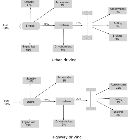
In the case of internal combustion engines, the sketch of the DoE shows that average car efficiency amounts to less than 20%. We can see for ourselves that braking in proportion to the useful mechanic energy amounts to 6/13 i.e. 46% in towns, and 2/20 i.e. 10% on motorways.
As regards electric cars, the DoE explains that the efficiency between the electric motor and the wheels amounts to 60% [49] (however for the overall conversion see Embodied energy#Embodied energy in the energy field).
Let us consider the electric motor efficiency [Note 1] and the braking proportion in towns and on motorways .


Let us introduce which is the recuperated proportion of braking energy. Theoretically, it can reach up to 80%.[Note 2] Thus in the best case.


Under these circumstances, being the energy flux arriving at the electric engine, the energy flux lost while braking and the recuperated energy flux, an equilibrium is reached according to the equations


and


thus

It is as though the old energy flux was replaced by a new one

The expected gain amounts to

The higher the recuparation efficiency, the higher the recuperation.
The higher the efficiency between the electric motor and the wheels, the higher the recuperation.
The higher the braking proportion, the higher the recuperation.
See also
References
- ↑ GM patent 5775467 – Floating electromagnetic brake system- Erik Knuth, Abraham Farag, Loren Majersik, William Borchers.
- ↑ GM patent 5603217 – Compliant master cylinder- Loren Majersik, Abraham Farag.
- ↑ Dave (16 March 2009). "Horseless Carriage: 1906". Shorpy. Retrieved 14 August 2010.
- ↑ Raworth, Alfred (7 February 1907). "Regenerative control of electric tramcars and locomotives". Proceedings of the Institution of Electrical Engineers 1906–1907. 38: 374–398. Retrieved 11 March 2014.
- ↑ Discussion on the 'Regenerative braking of electric vehicles' (Hellmund) Pittsburg, PA. Transactions of the American Institute of Electrical Engineers. 36. 1917. p. 68. Retrieved 11 March 2014.
- 1 2 Jno, Struan; Robertson, T.; Markham, John D. (2007). The Regenerative Braking Story. Scottish Tramway & Transport Society.
- ↑ Transport World The Tramway and Railway World. XX. Carriers Publishing. July–December 1906. p. 20. Retrieved 11 March 2014.
- ↑ Bigpanzer (30 April 2006). "Susrami Type Locomotoive at Surami Pass". Shorpy. Retrieved 31 January 2011.
- ↑ Railvolution magazine, 2/11, Kiruna Locomotives, Part 1
- ↑ Næss, Per (3 August 2007). "Evighetsmaskiner". Fremover (in Norwegian). p. 28.
- ↑ Hart, Lee A. (28 December 2013). "EV Motor Controllers". Retrieved 4 May 2014.
- ↑ Leno, Jay (1 May 2007). "The 100-Year-Old Electric Car". Popular Mechanics. Retrieved 4 May 2014.
- ↑ Ayres, Robert U.; McKenna, Richard P. (1972). "The Electric Car". Alternatives to the internal combustion engine: impacts on environmental quality. Johns Hopkins University Press. p. 219. ISBN 978-0-8018-1369-6. Retrieved 4 May 2014.
- ↑ "Regenerative braking boosts green credentials". Railway Gazette International. 2 July 2007. Retrieved 11 March 2014.
- ↑ "Delhi Metro prevents 90,000 tons of CO2". India Times. 23 February 2009. Archived from the original on 26 February 2009. Retrieved 14 August 2010.
- ↑ "Flywheel firm launches". Railway Gazette. 20 January 2011. Retrieved 11 March 2014.
- ↑ "Milestones Reached on the Jubilee and Victoria Lines". London Reconnections. 2 August 2011. Retrieved 11 March 2014.
- ↑ Solomon, Brian (2014). GE and EMD Locomotives. Voyageur Press. pp. 59–61.
- 1 2 "Team Lotus, Virgin, HRT F1 to Start 2011 Without KERS". Autoevolution. 28 January 2011. Retrieved 1 June 2011.
- ↑ BBC TV commentary on German Grand Prix 2009
- ↑ Flybrid Systems LLP (10 September 2010). "Flybrid Systems". Flybrid Systems. Retrieved 17 September 2010.
- ↑ Torotrak Archived 14 October 2008 at the Wayback Machine.
- ↑ "Torotrak, Xtrac & CVT pdf" (PDF). Retrieved 17 September 2010.
- ↑ BHR Technology. "Cpc-Kers". Bhr-technology.com. Retrieved 17 September 2010.
- ↑ "KERS failure caused Red Bull fire scare". autosport.com. 17 July 2008. Retrieved 22 July 2008.
- ↑ "BMW mechanic escapes KERS scare". autosport.com. 22 July 2008. Retrieved 22 July 2008.
- ↑ "Teams Comment on F1's Environmental Future". FIA. 8 October 2008. Retrieved 14 January 2009.
- ↑ "2009 Formula One Technical Regulations" (PDF). FIA. 22 December 2006. Retrieved 22 December 2006.
- ↑ FIA management (22 December 2006). "2009 FORMULA ONE TECHNICAL REGULATIONS" (PDF). FIA. Retrieved 8 July 2008.
- ↑ Whyatt, Chris (30 August 2009). "Raikkonen wins exciting Spa duel". BBC. Retrieved 30 August 2009.
- ↑ "Formula 1 - The Official F1 Website". Formula1.com. Retrieved 14 August 2010.
- ↑ "http://www.formula1.com/news/headlines/2010/12/11603.html". formula1.com. Retrieved 4 December 2010. External link in
|title=(help) - ↑ Benson, Andrew (23 June 2010). "Changes made to F1l". BBC. Retrieved 23 June 2010.
- ↑ "Formula 1 delays introduction of 'green' engines until 2014". bbc.co.uk. 29 June 2011. Retrieved 27 June 2011.
- ↑ "Bosch Developing Modular KERS Systems for Range of Motorsport Applications". Green Car Congress. 18 November 2008. Retrieved 27 April 2010.
- ↑ http://www.carmondo.de/blog/2008/07/03/honda-und-bmw-mit-formel-1-hybriden/ (German)
- ↑ "Peugeot Sport Hybrid". Racecar Engineering. 13 September 2008. Retrieved 13 September 2008.
- ↑ "Hybrid Air, an innovative full hybrid gasoline system". PSA-Peugeot-Citroen. Retrieved 4 May 2014.
- ↑ "The Car That Runs On Air". Popular Science. 25 February 2014. Retrieved 4 May 2014.
- ↑ Lawrence Butcher (18 September 2008). "F1 KERS; McLaren on track with KERS | People". Racecar Engineering. Retrieved 14 August 2010.
- ↑ McLaren to work with Freescale on KERS 12 November 2008
- ↑ "Toyota Hybrid Race Car Wins Tokachi 24-Hour Race; In-Wheel Motors and Supercapacitors". Green Car Congress. 17 July 2007. Retrieved 17 September 2010.
- ↑ "BMW EfficientDynamics : Brake Energy Regeneration". www.bmw.com. Retrieved 2016-01-03.
- ↑ "BlueMotion Technology < Technical glossary < Volkswagen Technology & Service | VW Australia". www.volkswagen.com.au. Retrieved 2016-01-03.
- ↑ "KTM beats F1 with secret KERS debut! | MotoGP News | February 2009". Crash.Net. 4 February 2009. Retrieved 14 August 2010.
- ↑ "Hydraulic Hybrid Bicycle Research". EPA.
- ↑ "ACO Technical Regulations 2008 for Prototype "LM"P1 and "LM"P2 classes, page 3" (PDF). Automobile Club de l'Ouest (ACO). 20 December 2007. Archived from the original (PDF) on 25 June 2008. Retrieved 20 January 2008.
- ↑ Sam Collins (13 September 2008). "Peugeot Sport Hybrid | People". Racecar Engineering. Retrieved 14 August 2010.
- ↑ fuel economy website fueleconomy.gov
- ↑ The electric motor, power electronics as well as the battery are supposed to show an efficiency which is equal to 90%, whereas the efficiency of power train is supposed to be equal to 80 %. In this case, the overal efficiency would amount to 58.3 %, which is very close to the value of 60% given by the DoE.
- ↑ The electric motor, and power electronics are supposed to show an efficiency which is equal to 90%, leading to an efficiency of 81 %. For recuperating such an amount, the car must know precisely when braking energy has to be recuperated, which is impossible. The recuperated amount will be lower, except maybe during braking cycles, which are known.