SBB-CFF-FFS Be 3/5
|
Be 3/5 number 12201 in the 1930s | |||||||||||||||||||||||||||||||||
| |||||||||||||||||||||||||||||||||
| |||||||||||||||||||||||||||||||||
| |||||||||||||||||||||||||||||||||
| |||||||||||||||||||||||||||||||||
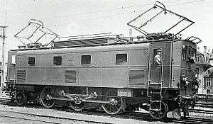
The Be 3/5 12201 was one of four test locomotives ordered by the Schweizerischen Bundesbahnen (Swiss Federal Railways) (SBB) in June 1917. Intended to provide experience with electric traction, the locomotive was intended, along with Be 4/6 12301, Be 4/6 12302 and Ce 6/8I14201, to be used on services on the Gotthardbahn (Gotthard railway). The Be 3/5 was something of a stopgap offered by Maschinenfabrik Oerlikon (MFO) because they felt that the requirements required for the Gotthard Railway could not be fulfilled at the time. As the MFO did not feel that it could produce a freight locomotive with six drive-axles, a smaller version of the BLS Be 5/7 was offered. This meant that the locomotive did not fulfil the SBB specifications for the Gotthard line; it was too weak and, compared with the A 3/5 steam locomotives, too slow. However, due to a lack of available stock, the railway still took delivery of the locomotive, a decision later proved correct by the long operational life and reliability of the Be 3/5.
History
In November 1913 the executive board of the Schweizerischen Bundesbahnen (Swiss Federal Railways) (SBB) decided to electrify the Gotthardbahn (Gotthard railway) from Erstfeld to Biasca, but this was not effected immediately. The main impetus was the coal shortage caused by World War One. Due to a lack of fuel, the SBB had to reduce schedules more and more and, by autumn 1918, on Sundays only milk trains were running. Following the conflict, the SBB electrified, along with other important lines, the Gotthard railway line, completing this in 1920. To serve those lines the SBB urgently needed passenger and freight locomotives.
Requirement specifications
The SBB required locomotives from the industry which complied with these requirements:
- A weight per running meter of at most 7 t/m
- A maximum axle load of 18 t (18 long tons; 20 short tons), and later – after the infrastructure had been adapted – 20 t (20 long tons; 22 short tons)
- Haulage of towed load of 430 t (420 long tons; 470 short tons) at a gradient of 26 ‰ (2.6%) with 35 km/h (22 mph)
- Reliable run-up with this load at a gradient of 26 ‰ (2.6%) and acceleration to 35 km/h (22 mph) within 4 minutes
- Two outward and return journeys Arth-Goldau – Chiasso within 28 hours (780 km or 480 mi)
- Electrical brake to decelerate the locomotive on slopes
- Overload of 20% during 15 minutes without damages
Commissioning and proposal
Maschinenfabrik Oerlikon (MFO) was commissioned to design and construct a freight locomotive that met these requirements and was given great freedom in their design. At it transpired, the locomotive from MFO did not comply with the requirements specifications at all. Nevertheless, the SBB took over the locomotive.
Technical details
The mechanical part
Running Gear
The running gear consisted of three drive-axles mounted in the locomotive frame. The center drive-axle had a side-play of 2 x 25 mm (0.984 in). The two idle-axles were mounted in Bissel trucks which were fixed to the frame. Those axles had a side-play of 2 x 80 mm (3.15 in).
Transmission of tractive force
The tractive force was transmitted from the drive-axles to the frame. From there the force was carried over to the towing hook and the buffers.
Drive
The two motors were mounted in half height in the locomotive frame. Those two motors drove big cogwheels over sprockets spring-loaded on both sides. Each of those big cogwheels drove a jackshaft. The two jackshafts drove a shared slit coupling rod which drove – over a vertical crosshead – the crank pin of the center drive-axle. Side rods connected to the slit coupling rod transmitted the force to the outer drive-wheels.
This drive concept was later used at the Ae 3/6 II.
Locomotive body
The locomotive body consisted of a frame built up with 25 mm (0.984 in) thick steel plates. On this frame the body was mounted with a cab at each end. The towing hook and the buffers were fixed to an abutment beam which was mounted to the frame.
The electrical part
Primary circuit
The electrical part was – in its arrangement – taken over from the Be 5/7 of the BLS. It consisted of a diamond-shaped pantograph, an electrical cutting knife for cutting off the respective pantograph, lightning protection inductor and one more electrical cutting knife for disconnection of one half of the locomotive. All those components were mounted on the roof. The oil propulsed main switch was located in the locomotive body. The locomotive driver operated the switch over electric valves located in both cabs. It was also possible to handle the switch mechanically over a rod system. Finally it was possible to manipulate the main switch directly by using a wrench.
The two transformers were – unusual at the SBB – air ventilated. The design was the same as the Be 5/7 of the BLS. The switches were fixed to the transformers. The connection to the respective voltage steps was executed with contact camshafts. The switching process was started with special sparkle extinguishing camshafts. The step switch used compressed air and had 12 steps. Since the two switches were operated alternatively, this meant that 23 steps were required which meant that the switching time was very slow. To operate the step switches, the locomotive driver had to turn a vertical crank handle once for each step. It was possible to shut off power by running down both step switches with a special handle.
The electropneumatical reverse switches were attached on the motors. A group switch was mounted by them which had to execute the following actions in case of a failure:
- Separation of one transformer with its respective motor → Full speed, but only half tractive force
- Separation of one transformer and feeding the two motors from the other one → Only half speed, but full tractive force
In 1929 the delicate step switches were replaced by two hopper switches. The old controllers were at the same time exchanged to normal controllers with horizontal hand wheels.
Auxiliary systems
The locomotive consisted of the following 100 V operated auxiliary systems:
- two compressors
- three fan groups (two for the transformers and one for the engine rooming)
- Motor-generator for charging the batteries for control power and lighting
- cab heating
The two old compressors were upgraded later to a modern MFO-compressor, which ran with the later auxiliary systems voltage of 220 V.
The train heating system was fed over a separate oil propulsed main switch with 1000 V. This installation was later replaced by a spearte heating transformer. The oil powered main switch was replaced by a heating hopper.
Electrical brake
The SBB requirement requested an electrical brake. This brake was shown in the blueprints but only in dashed lines and therefore not mounted in the locomotive. This brake was never upgraded because this “stopgap” locomotive was never used for services on the Gotthard railway line.
Multiple-unit Control
The locomotive was equipped was a multiple-unit control. The idea behind this was to lead a 425 t-train on the adjacent lines with low gradient using a Be 4/6 and then boosting it up for the steep gradients at the gotthard railway line using a Be 3/5. The idea of operating the train with one locomotive driver on the leading locomotive was definitely plausible. But the problem was, that for driving back the locomotive to the starting point another locomotive driver was needed. It is unknown if the multiple-unit control ever was tested.
Delivery date
The locomotive was delivered at 16 April 1919. She was assigned – as were all the test locomotives – to the Bern depot. From Bern the machine pulled trains of all types up to Spiez. In the year of delivery, it travelled a remarkable 65,000 km. But that was a performance the Be 3/5 never achieved again.
By 1923 the locomotive was assigned to the Zürich depot, pulling commuter trains and travelling approximately 10,000–20,000 km per year. In March 1928 she was relocated to the Luzern depot. There she replaced the Be 2/5 11001 operating from Zug in the triangle Zug – Lucerne – Arth-Goldau with any kind of trains.
Up to 1934 the maintenance shop of Zurich was responsible for the care of the locomotive. Later the responsibility went over to the maintenance shop of Yverdon. This shop warned the Traction and Maintenance Department of the SBB in Bern 1942 that the commutators of the motors were almost fully worn. In the same time Yverdon remarked that a replacement of the winding of the transformers was necessary. Since the locomotive did not require a very extensive maintenance effort compared with other locomotives the Lucerne depot did not consider the call as dramatic.
In September 1950 the commutators had to be replaced in a very costly repaire during which a screw fell into the gear which led to such damage that the Yverdon shops requested the locomotive be retired in 1957. Bern, however, again ordered the locomotive repaired, which it was, although it needed more repair when a transformer burned in 1958.
Even after a collision at 13th in Rotkreuz the Be 3/5 was not discarded. The locomotive was then equipped as heating locomotive to heat up coaches before their use and retired from line and switching services.
From 1963 the Be 3/5 was used as an auxiliary car locomotive, heating locomotive, depot transformer and compressed-air donor. In 1968 it was equipped with cross-ties and was used as a dummy-object for the rerailing crew of the Lausanne depot. In November 1973 the locomotive was scrapped in Yverdon.
References
- Schneeberger, Hans (1995). Die elektrischen und Dieseltriebfahrzeuge der SBB, Band I: Baujahre 1904-1955 (in German). Luzern: Minirex AG. ISBN 3-907014-07-3.
- Jeanmaire, Claude. Die elektrischen und Diesel-Triebfahrzeuge schweizerischer Eisenbahnen, Die Lokomotiven der Schweizerischen Bundesbahnen (SBB) (in German). ISBN 3-85649-036-1.
| SBB-CFF-FFS |
|  | ||||||||||||||||||||||||||
|---|---|---|---|---|---|---|---|---|---|---|---|---|---|---|---|---|---|---|---|---|---|---|---|---|---|---|---|---|
see also Category:Locomotives of Switzerland, Swiss locomotive and railcar classification | ||||||||||||||||||||||||||||