SBB-CFF-FFS Be 4/6 12302
|
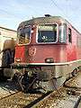
Be 4/6 number 12302 in the 1930s | |||||||||||||||||||||||||||||||
| |||||||||||||||||||||||||||||||
| |||||||||||||||||||||||||||||||
| |||||||||||||||||||||||||||||||
| |||||||||||||||||||||||||||||||

The Be 4/6 12302 was one of four test locomotives ordered by the Schweizerischen Bundesbahnen (Swiss Federal Railways) (SBB) in June 1917, along with the Be 3/5 12201, Be 4/6 12301 and Ce 6/8I14201. It was intended to be used on the Gotthardbahn (Gotthard railway), in order to gain experience in ordering and operating electric locomotives, However, the Be 4/6 12302 was never used for scheduled services on the Gotthard, because at its introduction it was already outperformed by the successor class Be 4/6 12303-12342.
History
In November 1913 the executive board of the Schweizerischen Bundesbahnen (Swiss Federal Railways) (SBB) had decided to electrify the Gotthardbahn (Gotthard railway) between Erstfeld and Biasca. During the First World War, a shortage of imported coal meant that the SBB needed to reduce schedules more and more severely as time went on, to the point - in the autumn of 1918 - where on Sundays only milk trains were able to run. As a result, the electrification of the Gotthard and other important lines was made a priority.
The electrification of the Gotthard was completed in 1920, with new passenger and freight locomotives being urgently needed.
Requirements, contract and delivery
The SBB specified that the locomotive should meet their requirements of:
- Top speed of 75 km/h (47 mph)
- Ability to haul a train of 300 t (300 long tons; 330 short tons) on a gradient of 26‰ at 50 km/h (31 mph)
- Able to start from an standstill with this load and gradient, and accelerate to that speed within 4 minutes
- Three outward and return journeys Arth-Goldau – Chiasso within 24 hours - a total run of 1,360 km (850 mi)
- Electrical brake for use on downward slopes
- Multiple-unit control
The contract for the design and construction of the locomotive was awarded to Brown, Boveri & Cie (BBC). Subject to the requirements above, the company was free to implement the design as they wished.
The locomotive was delivered on 19 April 1919, the third of the four test locomotives. It was used for numerous test runs on the Lötschberg line.
Technical details
The mechanical part
Running gear
The running gear consisted of two bogies. Each had two drive axles, one idle axle in a Bissel truck, and a jackshaft. The idle axles had a side play of 2x70 mm relative to the bogie frame.
Transmission of tractive force
The tractive force was transmitted from the drive axles to the bogies. From there the force was carried to the bogie mounted towing hook and the buffers. The bogies were connected together with a so-called short coupling. The locomotive body did not carry any tractive forces.
Drive
Two motors were mounted in each bogie frame. The motors drove large cogwheels via spring-loaded sprockets on each side, and the cogwheels drove a jackshaft. The crank pins of the jackshafts drove – via a coupling rod – the crank pins of the two outer drive axles of the bogie. The inner side of this coupling rod contained a pin, which drove the crank pins of the two inner drive axles via a second coupling rod. Because of the position of the motors, and therefore also the jackshaft, the coupling rods were offset slightly relative to the drive axles. From a maintenance point of view this kind of drive was cheaper than a complex split coupling rod, but during service it was considerably more bumpy. For this reason primarily, the locomotive was not used for high speed operation.
Locomotive body
The locomotive body consisted of a single bridging slab, onto which the body parts were fixed The locomotive body had no front cabinets. The bridging slab only rested on the bogies; no tractive forces were carried over the body.
Braking equipment
The automatic Westinghouse air brake and the locomotive brake acted in both bogies on both sides of the driving wheels of each drive axle. The idle wheels did not have brakes. Each cab was equipped with a handbrake which acted on the respective bogie.
The electrical part
Primary circuit
Two diamond-shaped pantographs – controlled by a valve in each cab – led the current from the catenary to the two isolator switches on the roof of the locomotive. From these switches the current was transferred to the oil-cooled transformer via a lightning protection inductor and the oil-operated main switch. The transformer, weighing 12.5 t (12.3 long tons; 13.8 short tons), was located in the centre of the locomotive body. The transformer oil was cooled via an oil pump and a system of tubes on both sides of the locomotive body, themselves cooled by the air flow and the fan apertures in the body behind them. These cooling tubes were the main part of the distinctive appearance of the locomotive and its successors Be 4/6 12303-12342.
The stepping switch transmitted the traction current to the motors, which were connected in series circuit. The flat track stepping switch was mounted on the transformer and consisted of 18 steps providing voltages between 237V and 1350V. To suppress sparks during switching, spark switches were used. The switch was operated by a 36V motor powered by a battery. To operate the step switches the locomotive driver had to turn a vertical crank handle, later changed to a horizontal controller. These controllers drove two polarized relays, which switched up until the requested step was reached.
Eacl of the two motor groups was provided with a reversing switch. For overload protection each also had an electrically driven oil-operated switch with an overcurrent relay.
Auxiliary systems
The locomotive's auxiliary systems, operated by 220V, were:
- two piston compressors
- four fan groups for the motors
- one oil circulating pump for transformer cooling
- one motor-generator for battery charging
- cab heating, foot and oil heating plates
The train heating system was powered directly from the transformer, switchable between 600V, 800V or 1000V.
Electrical brake
A resistor electrical brake (not a regenerative brake) was installed. During braking the motors were disconnected from the catenary and operated as DC generators. The power generated was dissipated by the brake resistors mounted on the roof, cooled by the air flow.
The equipment for this was tested but later dismantled, because the locomotive – as with the two other Be-class prototype locomotives – was never used in regular service on the Gotthardbahn (Gotthard railway).
Multiple-unit control
The locomotive was equipped with multiple-unit control, but it was never tested or used.
Service
The locomotive was delivered on 19 April 1919 as the third of the four test locomotives, but was not used for scheduled services on the SBB Bern – Thun line. The locomotive was used for extensive test runs on the Lötschbergbahn.
Later in 1919 the locomotive operated scheduled services - commuter and freight - between Bern and Thun, and later to Spiez. In November 1919 she operated scheduled services to Brig, together with Be 4/6 12301. Later those services continued together with the Be 4/6 12303-12342 series locomotives, delivered in April 1920, over the Lötschberg line. At the inauguration of the electric service on the Gotthardbahn this locomotive was unique; its only trips over the Gotthard were the transfers to the Bellinzona workshop.
Based in the Bern depot, the locomotive mainly operated commuter and freight trains. From May 1956 onwards it was moved to Biel depot and operated similar services. From the beginning of 1959 the locomotive worked on the hump of the marshalling yard at Biel, and from May 1962 operated scheduled services again.
After the fire on Be 4/6 12301, 12302 took over the hump of the Lausanne marshalling yard at Renens. Unfortunately in May 1965 a short circuit in the transformer put the locomotive out of action. There was no fire, but due to the high cost of a repair the locomotive was withdrawn on 31 May 1965.
The Be 4/6 12302 was unique but the simple concepts of the locomotive were proven by the Be 4/6 12303-12342 series. The extremely bad running characteristics - compared with the Be 4/6 12301 - were taken account of during the scheduled services which mostly used maximum speeds of only 50 km/h (31 mph).
References
- Schneeberger, Hans (1995). Die elektrischen und Dieseltriebfahrzeuge der SBB, Band I: Baujahre 1904-1955 (in German). Luzern: Minirex AG. ISBN 3-907014-07-3.
- Jeanmaire, Claude. Die elektrischen und Diesel-Triebfahrzeuge schweizerischer Eisenbahnen, Die Lokomotiven der Schweizerischen Bundesbahnen (SBB) (in German). ISBN 3-85649-036-1.
| SBB-CFF-FFS |
|  | ||||||||||||||||||||||||||
|---|---|---|---|---|---|---|---|---|---|---|---|---|---|---|---|---|---|---|---|---|---|---|---|---|---|---|---|---|
see also Category:Locomotives of Switzerland, Swiss locomotive and railcar classification | ||||||||||||||||||||||||||||