List of home computers by video hardware
This is a list of home computers, sorted alphanumerically, which lists all relevant details of their video hardware.
A home computer was the description of the second generation of desktop computers, entering the market in 1977 and becoming common during the 1980s. A decade later they were generally replaced by IBM PC compatible "PCs", although in actuality home computers are also members of the class known as personal computers.
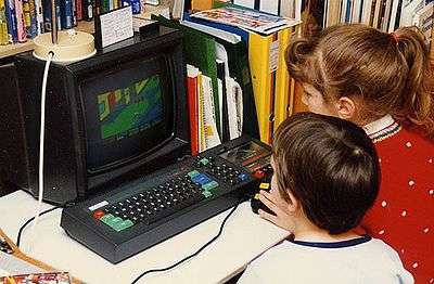
Examples of typical early home computers are the TRS-80, Atari 400/800, BBC Micro, the ZX Spectrum, the MSX 1, the Amstrad CPC 464 and the Commodore 64. Examples of typical late home computers are MSX 2 systems, and the Amiga and Atari ST systems.
Note: in cases of manufacturers who have made both home and personal computers, only machines fitting into the home computer category are listed. Systems in the personal computer category, except for Early Macintosh personal computers, are generally all based on the VGA standard, and use a video chip known as a Graphics processing unit. Although very early PCs used one of the much simpler (even compared to most home computer video hardware) video display controller cards, using standards such as the MDA, Hercules Graphics Card, CGA and EGA standard). Only after the introduction of the VGA standard could PCs really compete with the home computers of the same era, such as the Amiga and Atari ST, or even with the MSX-2. Also not listed are systems that are typically only gaming systems, like the Atari 2600 and the Bally Astrocade, even though these systems could sometimes be upgraded to resemble a home computer.
The importance of having capable video hardware
Early home computers all had quite similar hardware, (and software) mostly using the 6502, the Z80, or in a few cases the 6809 microprocessor. They could have only as little as 1 KB of RAM or as much as 128K, and software wise, they could use a small 4K BASIC interpreter, or an extended 12K or more BASIC. So the basic systems were quite similar, except for one part of the system, the video display hardware. Some systems proved to be much more successful than others, and careful observers will see that the most successful systems had the most capable video hardware. The reason for that is that the success of the home computer was mostly determined by the kind of games you could play on it.
If you wanted to run a nice video game on a home computer, all the other specifications of the system, such as the CPU, the kind of BASIC, even to a degree how much memory the system had (if had at least 32K or more) did not matter much. What mattered most was what kind of picture could be put on the screen, and how easy or hard it was for a programmer to get enough capabilities out of the video hardware to create the effects necessary for the game.
A case in point is the Commodore 64. Its microprocessor lacked advanced math functions and was relatively slow. In addition, the built-in BASIC interpreter lacked any sort of graphics commands, as it was the same version that was developed for the older Commodore PET (a computer without any high resolution graphics capabilities at all). However, these drawbacks were of little consequence, because the C64 had the VIC-II chip. When accessed by machine language programs, the graphic capabilities of this chip made it practical to develop arcade-style games.[1] Additionally, specific machine language coding exploiting quirks of the VIC-II chip allowed for special tricks to draw even better pictures out of the VIC-II chip.[2] The comparatively large memory and the audio capabilities of the C64 also lent themselves well toward the production of desirable games. A negative example was the Aquarius by Mattel which had such incredibly limited video hardware (for the time period) that it was retracted from the market after only four months due to bad sales.
Video Arbitration Logic
One major problem that early computer video hardware had to overcome was the Video bus arbitration problem. The problem was to give the video hardware (VDU) continuous read access to the video RAM, while at the same time the CPU also had to access the same RAM. The obvious solution, using interleaving time slots for the VDU and RAM was hard to implement because the logic circuits and video memory chips of the time did not have the switching speed they have now. For higher resolutions the logic and the memory chips were barely fast enough to support reading the display data, let alone for dedicating half the available time for the slow 8-bit CPU. That said, there was one system, the Apple II, that was one of the first to use a feature of the data-bus logic of the 6502 processor to implement a very early interleaving time slot mechanism to eliminate this problem. The BBC Microcomputer used 4 MHz RAM with a 2 MHz 6502 in order to interleave video accesses with CPU accesses.
Most other systems used a much simpler approach, and the TRS-80's video logic was so primitive that it simply did not have any bus arbitration at all. The CPU had access to the video memory at all times. Writing to the video RAM simply disabled the video display logic. The result was that the screen often displayed random horizontal black stripes on the screen when there was heavy access to the video RAM, like during a video game.
Most systems avoided the problem by having a status register that the CPU could read, and which showed when the CPU could safely write to the video memory. That was possible because a composite video signal blanks the video output signal during the "blanking periods" of the horizontal and especially the long vertical video sync pulses. So by simply waiting for the next blanking period the stripes could be avoided. This approach did have one disadvantage, it relied on the software not to write to the screen during the non-blanking periods. If the software ignored the status register the stripes would re-appear. Another approach, used by most other machines of the time, was to temporarily stop the CPU using the "WAIT/BUSRQ" (Z80) "WAIT" (6809) or "SYNC" (6502) control signal whenever the CPU tried to write to the screen during a non-blanking period. Yet another, more advanced, solution was to add a hardware FIFO so that the CPU could write to the FIFO instead of directly to the RAM chips, which were updated from the FIFO during a blanking interval by special logic circuitry. Some later systems started using special "two port" video memory, called VRAM, that had independent data output pins for the CPU interface and the video logic.
The main classes of video hardware
There are two main categories of solutions for a home computer to generate a video signal.
- a custom design, either built from discrete logic chips, or with some kind of Programmable logic device.
- a system using some form of Video Display Controller (VDC), a VLSI chip that contained most of the logic circuitry needed to generate the video signal.
Systems in the first category were the most flexible, and could offer a wide ranges of (sometimes unique) capabilities, but generally speaking the second category could offer a much more complex system for a comparable lower price.
The VDC based systems can be divided into four sub-categories.
- Simple video shift register based solutions, have a simple "video shifter chip", and the main CPU doing most of the complex stuff. Only one example of such a chip for a home computer exists, the RCA CDP1861 used in the COSMAC VIP. It could only create a very low resolution monochrome graphic screen. The chip in the Sinclair ZX-81 also is a video shifter, but is not a dedicated chip but a programmable chip, a ULA. The CDP1861 however was specially designed for this task only. Dedicated Video shifter chips did have some use in very early game systems, most notably the Television Interface Adapter chip in the Atari 2600. Note that although one of the chips in an Atari ST is also called a "video shift register" it does not fall into this class, mainly because the IC's in this class depend on the main CPU to feed them with picture data. They do nothing more than generate the sync signals and convert parallel data into a serial video data stream. The Atari ST's chip used a DMA system to read out video data independent of the main CPU, and contained a palette RAM, and resolution/color mode switching logic.
- CRTC (Cathode Ray Tube Controller) based solutions. A CRTC is a chip that generates most of the basic timing and control signals. It must be complemented with some "Video RAM" and some other logic for the "arbitration", so that the CPU and the CRTC chip can share access to this RAM. To complete the design, a CRTC chip also needs some other support logic. For example, a ROM containing the bitmap font for text modes, and logic to convert the output from the system into a video signal.
- Video interface controllers were a step up on the ladder, these were true VLSI chips that integrated all of the logic that was in a typical CRTC based system, plus a lot more, into a single chip. The VIC-II chip is probably the best known chip of this category.
- Video co-processor chips are at the highest end of the scale; Video interface controllers that can manipulate, and/or interpret and display, the contents of their own dedicated Video RAM without intervention from the main CPU. These chips are highly flexible offering options and features with minimal CPU involvement that on other systems are impossible or at best difficult to produce, requiring extensive CPU overhead. The Atari ANTIC/GTIA and Amiga OCS/ESC/AGA are well known examples of this high-feature category. But note that not all video co-processors are powerful, some are even simpler than many Video interface controllers, notably the primitive SAA5243 which is still technically a co-processor.
Explanation of the terms used in the tables
- System Name, the name of the system, or if there are many similar versions, the name of the most well known variant, see Notes.
- Year the year that the first version of this system came on the market.
- Chip name the name of the chip that was used as the basis for the video logic.
- Video RAM the maximum amount of RAM used for the video display, depending on the resolution used the system may use less.
- Text mode(s) The numbers of characters per line and lines of text the system supported. Sometimes more than one mode was possible
- Font extras describes extra graphical possibilities a video system had because of optional features of their character sets, there are currently three categories:
- LC Some systems could only display upper case characters in text mode because of their limited character set, If a system was able to also support lower case letters in a text mode, (in any highres mode it is of course always possible), then there is LC (for Lower Case) in this column.
- BG Some systems used a matrix of blocky pixels instead of a letter in their font sets (or used dedicated hardware to emulate them, like the TRS-80 did), to support some sort of all points addressable (APA) mode. Its hard to call this a "high resolution" mode, because the resolution could be as low as 80×48 pixels, but in any case you could draw pictures with them. In case of systems that used such a system as its "APA" mode there is BG (for Block Graphics) in this column.
- SG Some other systems used semi graphical characters like box-drawing characters dots and card symbols, and "graphical building block" geometric shapes such as triangles to give the system the appearance it could do high resolution graphics while in reality it could not, Systems like that have SG (for semi graphical characters) in this column. Many systems like the PET had a few of such characters dedicated to block graphics for an APA mode as well, often only for 2×2 matrix characters. Sometimes the system filled (or could fill) a reprogrammable section of the font set which such characters, these systems mainly fall under the "soft font" heading. Note that the BG and SG entries are only used when the system relied on them, had them predefined in its default character set, or, (what often happened on early systems) had them printed on the keyboard keys for direct entry in combination with some kind of "graphic shift" key.
- Soft Font when the system had a programmable font RAM instead of a static "font ROM", or when the video system did not have a hardware text mode, but painted text in the highres screen using software, the video display wasn't dependent on a permanent font set, in this case we are talking about a system with a "soft" font.
- text colors The number of colors the characters could have. If more than one text mode is supported the text colors column also lists the same numbers in the same order.
- Graphics modes The number of horizontal and Vertical pixels the system could display in a high resolution mode, where several high resolution modes exist each one is listed separately.
- Graphics colors The number of colors each pixel could have in High resolution mode, If more than one high resolution mode is supported the graphics color mode also lists the numbers in the same order.
- Color resolution in "high resolution mode" it was often the case that a certain pixel could not be given an arbitrary color, often certain clusters of pixels, (quite often 8×8 pixels large) shared the same "color attribute", so as to spare video memory, as an 8-bit computer only had a 64 KB address space, and the CPU often had limited capabilities to manipulate video memory, therefore it was often necessary to keep the video RAM size as small as possible, so a minimum of the address space of the micro was used, and also the video content could be changed relatively rapidly.
- Palette Support If the system could translate a "logical color" into a (larger number) or true colors using a palette mechanism then this column lists the number of logical colors the palette could accept, and the number of colors it could translate to.
- HW accel short for Hardware acceleration can take several forms, the most obvious form is "bit blitting", that is the moving of groups of pixels from one place in video memory to another without the CPU doing any of the moving, another often used technique is hardware scrolling which in fact emulates moving the whole screen in the video ram, a third form of hardware acceleration is the use of sprites implemented in hardware. Some systems also supported drawing lines (and sometimes rectangles) using special line drawing hardware. The entry in the column reveals which methods the hardware supported with a two letters for each method.
- BL for blitter
- DR for hardware supported line drawing
- SC for hardware scrolling support
- SP for hardware sprite support
- TE for hardware Tile engine support in graphic mode
- Sprite details covers three facets of the sprite support hardware the system used. Each number in the table cell is preceded by two letters.
- S# for the first facet, is the total number of hardware sprites the system could support, in hardware (not counting re-use of the same hardware). if the system doesn't support hardware sprites at all the table cell only contains "-" . If S# is 1 then the single sprite is most often used to support a mouse cursor.
- SS for the second facet, is the size of the sprite in screen pixels. A sprite could be displayed by the hardware, as a matrix of horizontal by vertical pixels. If more than one sprite size mode is available each one is listed.
- SC for the third facet, is the number of Sprite colors, it gives the number of colors that a sprite could have. It is about the total number of colors that could be used to define the sprite (transparent NOT included), so if a sprite could only be displayed as a figure in a single color the number is 1. If more than one sprite size mode is available each one is listed.
- SP for the fourth facet, is the number of Sprites per scanline. Hardware spites use a kind of Z-buffer to determine which sprite is "on top". Availability of hardware to do this limits the number of sprites that can be displayed on each scanline. This number tells how many sprites could be displayed on a scanline before one of them became invisible because of hardware limitations.
- Unique features If the video display has unique features (or limitations) they will be listed here, if space is a limitation the remaining special features are expressed as notes.
a "-" in a table cell means that the answer is irrelevant, unknown or in another way has no meaning, for example the sprite size of a system that does not support hardware sprites.
a "?" in a table cell means that the entry has not yet been determined. if a ? follows an entry it means that other options than the listed ones may also exist
"Mono" in a table cell means monochrome that is for example black on white, or black on green.
The list of home computers, and their video capabilities
Systems using discrete logic
| System name | Year | Chip name | Video RAM | Text mode(s) | Font extras | soft fonts | text colors | semigraphics modes | semigraphics colors | graphics modes | graphics colors | color resolution | palette support | HW accel | Sprite details | unique features |
|---|---|---|---|---|---|---|---|---|---|---|---|---|---|---|---|---|
| Aamber Pegasus | 1981 | - | 512 Bytes | 32×16 | LC | Yes | Mono | Programmable characters | Mono | Programmable characters | Mono | - | None | - | Software driven video generation[3] | |
| ABC80 | 1978 | - | 1K | 40×24 | LC, BG | - | Mono | 78×72[4] | Mono | - | - | - | - | - | Videotex (Prestel) support[5] | |
| Apple I | 1976 | - | 720 Bytes[6] | 40×24 | [7] | - | Mono | None | None | - | - | - | Dumb terminal[8] | |||
| Apple II [9] | 1977 | - | 18K[10] | 40×24[11] | [12] | - | Mono[13] | 40×48[14] | 15[15] | 280×192[16] | 6[17] | 140×192[18] | None | - | 4 line "caption"[19] | |
| Apple III | 1980 | - | 64K | 40×24, 80×24 | LC | - | 16 | None | 280×192, 560×192 | 16, 2[20] | ? | - | ? | - | 228 programmable characters | |
| Commodore PET 2001 | 1977 | - | 1000 Bytes | 40×25 | BG, SG | - | Mono | 80×50 using part of its pseudo graphic characters set | Mono | Limited 320x200 using part of its pseudo graphic characters set | Mono | - | - | - | 9" Mono monitor, non ASCII (PETSCII) character set. | |
| Compukit UK101 [21] and clones | 1979 | - | 768 Bytes | 48×16 | LC, SG | No | Mono | 96x48 by programming 2x3 block characters in 64 characters of its font | Mono | With clever use of its firmware semigraphics characters, a limited 384x128 mode would be achievable | Mono | - | None | - | - | 256 character font |
| DAI Personal Computer | 1979 | -[22] | 31680 bytes[23] | 60x24,[24] 60x4[25] | LC | - | 4 or 16 | 88×65, 176×130[26] | 4 or 16 | 352×260, 528×240 | 4 or 16 | 88×65, 176×130, 352×260, 528×240 | 4 of 16[27] | - | - | split screen text and graphics mode |
| Datapoint 2200[28] | 1971 | - | 840 Bytes[29] | 80×12 | LC | - | Mono | None | None | - | - | - | Shift registers for RAM[30] | |||
| Exidy Sorcerer | 1978 | - | 1920 Bytes | 64×30 | LC, SG[31] | Yes | Mono | 128x90 [32] | Mono | Limited 512×240[33] | Mono | - | None | - | Programmable character set allowed TRS-80 and PET like graphics | |
| Galaksija | 1983 | - | 512 Bytes[34] | 32×16 | BG[35] | - | Mono | 64×48[36] | Mono | 256×208[37] | Mono | - | None | - | - | All systems were essentially "home built", on a single sided PCB. Like the ZX81 it was software driven.[38] |
| Grundy NewBrain | 1982 | - | max 20K | 32×25, 32×30, 40×25, 40×30, 64×25, 64×30, 80×25, 80×30 | LC, BG | - | Mono | 64x75, 64x90, 80x75, 80x90, 128x75, 128x90, 160x75, 160x90[39] | Mono | 256×256, 320×256, 512×256, 640×256 | Mono | - | None | ? | - | Built in one line VFD, Videotext mode support |
| Interact Home Computer[40] | 1979 | - | 2184 Bytes | 17×12 | [41] | [42] | 4 | 112×78 | 4 | None | - | 4 of 8 | - | no real text mode, characters drawn by software. | ||
| MUPID | 1983[43] | - | 64K[44] | 40×25 | LC, BG, SG | YES[45] | 16+16 | [46] | 16+16 | 320×240 | 16+16 | 320×240 | 16 fixed colors, and 16 chooseable from a palette of 4096 colors | ? | - | Designed by academics as a BTX terminal, but with the capabilities of a home computer[47] |
| Panasonic JR-200 | 1983 | - | 2K+2K[48] | 32×24[49] | LC, BG | - | 8[50] | 64×48[51] | 8[52] | 256x192[53] | 8[54] | - | None | - | none[55] | |
| PMD 85 | 1985 | - | 9600 Bytes[56] | 48×32[57] | LC[58] | - | 4 gray-scales, 4 colors for 85/3 | [46] | 4 gray-scales, 4 colors for 85/3 | 288×256 | 4 gray-scales, 4 colors for 85/3 [59] | - | 4 out of ? gray-scales, 4 out of ?[60] colors for 85/3 | 48x256 | - | no text modes, only a single 288×256x2 bits per pixel graphics mode |
| Jupiter Ace | 1982 | - | 2K[61] | 32×24 | LC, BG | - | Mono | 64×48[62] | Mono | - | - | - | - | none | ||
| LINK 480Z[63] | 1982 | - | 2K[64] | 40×25, 80×25 | LC | - | Mono | None | [65] | [66] | [67] | - | - | none | ||
| MZ-80K | 1979 | - | 1000 Bytes | 40×25 | LC, BG, SG | - | Mono | 80×50[68] | Mono | limited 320x200 | Mono | - | None | - | many well chosen pseudo-graphics characters[69] | |
| OSI Superboard II[70] | 1979 | - | 1K[71] | 32×32, 64x16 [72][73] | LC, SG | No | Mono[74] | 48X72, 96x45 normally visible out of total 64x96, 128x48[72] using 64 characters (pseudo graphics) of the 128 characters of the optional extended character set ROM | Mono[74] | 192x192, 384x120 normally visible out of limited 256x256, 512x128[72] using full extended character set ROM[75] | Mono[74] | - | None | - | - | 256 character font [76] |
| OSI C4P | 1980 | - | 2K | 64×32 | LC, SG | No | 8 | 128×64 using part of its pseudo graphic characters set | 8 | Limited 512x256 using its full pseudo graphic characters set | 8 | - | None | - | - | 256 character font |
| SOL-20 | 1976 | - [77] | 1K | 64×16 | LC, SG [78] | No | Mono | None | Limited 512x128 with MC6574 | Mono | - | - | - | - | One of the first systems with built in video hardware[79] | |
| Tiki 100 | 1984 | - | 32K | 40×25, 80×25, 160×25 | LC | Yes | 16, 4, 2 | None | 256×256, 512×256, 1024×256 | 16, 4, 2 | 256×256, 512×256, 1024×256 | 256 | SC | - | none | |
| TRS-80 Models I and III[80] | 1977,1980 | - | up to 1K[81] | 32×16 64×16 | LC,[82] BG | - | Mono | 64×48, 128×48 | Mono | None | - | None | - | The canonical system to use Text semigraphics [83] | ||
| TRS-80 Model 4 | 1983 | - | 1920 bytes | 32×16, 40x24, 64×16, 80x24 | LC, BG | - | Mono | 64×48, 80x72, 128×48, 160x72 | Mono | None | - | None | - | Can display full 640x240 or 512x192 graphics with a standardized expansion board | ||
| ZX80 | 1980 | - | 792 Bytes[84] | 32×24 | BG, SG | - | Mono | 64×48 [85] | Mono | 256×192 [86] | Mono | - | - | - | - | "slow mode", software generated display[87] |
Systems using simple Video Shift Registers
| System name | Year | Chip name | Video RAM | Text mode(s) | soft fonts | text colors | graphics modes | graphics colors | unique features |
|---|---|---|---|---|---|---|---|---|---|
| COSMAC VIP, Telmac 1800 | 1977 | CDP 1861 | 256 Bytes ![88] | None ![89] | Yes | Mono | 64×32[90] | Mono | Incredibly primitive |
| Oscom NANO | 1980 | CDP 1864 | 256 Bytes[88] | None[89] | Yes | Mono | 64x32[90] | Mono | Incredibly primitive |
| ETI 660, Telmac 2000 | 1981, 1980 | CDP 1864 | 1.5K [88] | None[89] | Yes | 8 | 64x192[91] | 8[92] | primitive but supporting color |
Systems using programmable logic
| System name | Year | Chip name | Video RAM | Text mode(s) | Font extras | soft fonts | Text colors | Semigraphics modes | semigraphics colors | Graphics modes | graphics colors | color resolution | palette support | HW accel | Sprite details | Unique features |
|---|---|---|---|---|---|---|---|---|---|---|---|---|---|---|---|---|
| Acorn Electron | 1983 | ULA codenamed "Aberdeen"[93] | 20K (max) [94] | 20×32, 40×25, 40×32, 80×25, 80×32 [95] | LC | Yes | 4 or 16, 2 or 4, 2 or 4, 2, 2 | [46] | 4 or 16, 2 or 4, 2 or 4, 2, 2 | 160×256, 320×256, 640×256, 320×200, 640×200 | 4 or 16, 2 or 4, 2, 2, 2 | 160×256, 320×256, 640×256, 320×200,[96] 640×200 | Yes | – | None | |
| Elektronika BK -0010/-0011 [97] | 1985 | ULA [98] | 16K[99] | 32×25, 64×25 [100] | LC | Yes | 4, 2 | [46] | 4, 2 | 256×256, 512×256 | 4, 2 | 256×256, 512×256 | Yes [101] | – | Hardware scrolling [102] | |
| Amstrad PCW | 1985 | ASIC [103] | 23K | 90×32 [95][104] | LC | Yes | Mono [105] | [46] | Mono | 720×256 | Mono [105] | – | – | SC | – | Scroll RAM [106] |
| Mattel Aquarius | 1983 | PLA1 [107] | 2000 bytes [108] | 40×25 | LC, BG | - | 16 [109] | 80×75 [110] | 16 | None | 40×25 | None | – | None [111] | ||
| Nimbus PC-186 | 1984 | FPGA [112] | 64K | 40×25, 80×25 | LC | – | 16 | [46] | 16 | 320×250, 640×350 | 16, 4 | 320×250, 640×350 | None | ? | – | Early x86-based non IBM-PC system with good graphics |
| Oric 1 [113] | 1983 | HSC 10017 ULA | 8K | 40×28 | LC [114] | Yes [115] | 8 | 80x84 through soft font | 8 | 240×200 | 8 | 40×200 [116] | None | – | Serial attributes like Ceefax and Prestel systems [117] | |
| SAM Coupé | 1989 | ASIC [118] | 24K [119] | 32×24, 85×24 [95] | LC | - | 16, 4 | [46] | 16, 4 | 256×192, 512×192 | 8 or 16, 4 | 32×24, 32×192 or 256×192; 512×192 | 16 entries 128 colors [120] | – | Backwards compatible with Sinclair Spectrum | |
| Thomson MO5 | 1984 | EFGJ03L gate array | 16K | 40×25 | LC | yes | 16 | 80x75 through soft font | 16 | 320×200 | 16 | 40×25 | – | ? | – | light pen |
| Thomson TO7 | 1982 | MC 13000 ALS gate array | 14000 bytes, either 15000 or 16000 bytes for TO7-70 [121] | 40×25 | LC | - | 8, 16 for TO7-70 | [46] | 8, 16 for TO7-70 | 320×200 | 8, 16 for TO7-70 | 40×200 [122] | None | ? | – | Light pen |
| Thomson systems MO6, TO8 and TO9+ | 1986 | custom TI gate array plus EF-9369P color palette | 64K | 40×25 and 80×25 | LC | yes | 4, 2 | 80x75, 160x75 through soft font | 4, 2 | 8 modes from 160×200 to 640×200 | 16 to 2 | from 160×200 to 640×200 | 16 entries 4096 colors | ? | – | none |
| TRS-80 Color Computer Model 3 | 1986 | GIME [123] | 72000 bytes [124] | 32, 40, 64, 80x16-24 | BG, LC | No | 9 or 16[125] | 64×32,[126] 64×48,[127] | 9, 16 or 256; 5, 16 or 256; | 64×64, 128×64, 128×96, 128×192, 160x192-225,[128] 256×192-225, 320x192-225, 640x192-225 | 2, 4, 16 or 256; 2, 4, 16 or 256; 2, 4, 16 or 256; 2, 4, 16 or 256; 2, 4, 16 or 256;[129] 2, 4, 16 or 256; 2, 4, 16 or 256; 2, 4 or 16 | ? | 64 or 512[130] in GIME-processed modes | ? | - | None |
| Sinclair ZX Spectrum | 1982 | ULA [131] | 6912 Bytes | 32x24[95] | LC, BG | – | 8 (15) [132] | 64x48 | 8 (15) [132] | 256×192 | 8 (15) [132] | 32×24 | None | – | color limitations [133] | |
| Timex/Sinclair TS2068 | 1983 | CPLD [134] | 12288 bytes (max) | 32×24[95] | LC, BG | - | 8 | 64x48, 128x48 | 8, 2 | 256×192, 256×192, 512×192 | 8, 8, 2 | 32×24, 32×192 | None | – | swapping between two 256×192 screens | |
| Sinclair QL | 1984 | ZX8301 ULA | 32K | 42×25, 85×25 | LC | Yes | 8, 4 | 84x75, 170x75 through soft font; 128x128, 256x128 stippled [135] | 8, 4 | 256×256, 512×256 | 8, 4 [136] | 256×256, 512×256 | – | hardware pixel-based blinking [137] | ||
| ZX81 | 1981 | ULA 2C184E / 2C210E [138] | 792 bytes[139] | 32×24 | BG | – | mono | 64×48 [140] | mono | 256x192 via assembly language routines | mono | 32×24 | None | - | - | Very low-cost design [141] |
Systems using a CRTC
| System name | Year | Chip name | Video RAM | Text mode(s) | Font extras | soft fonts | text colors | semigraphics modes | semigraphics colors | graphics modes | graphics colors | color resolution | palette support | HW accel | Sprite details | unique features |
|---|---|---|---|---|---|---|---|---|---|---|---|---|---|---|---|---|
| ABC 800 series | 1981 | MC6845 | 1K (800C), 2K (800M, 802, 806) + 128K (806) | 40x24, 80×24 | LC, BG | - | 8, 2 | 78x75 | 8 | 256×240, 512x240 (806) | 16 (806) | ? | ? | - | HR board for 800 and 802 provides 16K for 240×240 graphics in 4 of 8 colors | |
| Aster CT-80 | 1979 | MC6845 | 1K or 2K[142] | 64×16, 32×16, 80×25, 40×25 [143] | LC, BG, SG [144] | - | Mono | 128×48, 64x48, 160×75,[145] 80x75 [146] | 3 gray scales [147] | None | - | None | - | Dual memory map support[148] | ||
| Camputers Lynx | 1983 | MC6845 | 32K[149] | 40×24 [95][150] | LC | - | 8[151] | (Presumably 80x72) | 8 | 256×248 | 8 | ? | None | ? | - | fully pixel addressable in 8 colors, Slow, little memory left.[152] |
| Colour Genie | 1982 | MC6845 | 16K[153] | 40×24 [154] | LC, BG, SG | - | 16 [155] | Presumably 80×72 [156] | 16 | 160×96,[157] Limited 320×192 [158] using 8×8 pixel programmable characters | up to 16[159] | ? | None | ? | - | Programmable characters[160] |
| Commodore PET 4000 and 8000 series | 1980, 1981 | MC6845 | 1000 Bytes (4000), 2000 Bytes (8000) | 40×25 (4000), 80×25 (8000) | BG, SG | - | Mono | 80×50 (4000), 160×50 (8000) using part of its pseudo graphic characters set | Mono | Limited 320x200 (4000), 640x200 (8000) using part of its pseudo graphic characters set | Mono | - | - | - | 12" Mono monitor, non ASCII (PETSCII) character set. | |
| Compucolor II | 1977 | SMSC CRT5027 | 4K[161] | 64×32, 64×16 | BG | - | 8 | Presumably 128×96, 128x48 through block graphics characters included in font, 128×128 [162] | 8 | Limited 512x256 | 8 | ? | None | ? | - | 13 " built in color screen,[163] |
| Comx-35 and clones | 1983 | CDP1869 CDP1870 | 3K [164] | 40×24 [165] | BG, SG [166][167] | - | 8 foreground (4 colors per 6×8 or 6×9 pixels, 1 per 6 pixel line)+ 8 background (for the whole screen) | 80×72 [168]/120×96 [169] | 8 foreground (4 colors per 6×8 or 6×9 pixels, 1 per 6 pixel line)+ 8 background (for the whole screen) | Limited 240×192 (NTSC)/240x216 (PAL)/240x384 (expanded RAM) [170] | 8 foreground (4 colors per 6×8 or 6×9 pixels, 1 per 6 pixel line)+ 8 background (for the whole screen) | 8 foreground + 8 background out of ? | None | - | None | |
| Durango F85 | 1977 | Intel 8275 | 2 KB | 80×24, 64×16 | LC, BG | - | Mono | Presumably 160x72, 128x48 | Mono | None | - | None | ? | - | 9" built in CRT | |
| Kaypro II series | 1982 | MC6845 | 2 KB | 80×24 | LC, BG [171] | - | Mono | Presumably 160x72 | Mono | None | - | None | ? | - | 9" built in CRT | |
| LNW-80 | 1982 | MC6845 | 1K or 2K | 80×24, 64×16, 32×16 | LC, BG | - | 8 | 160×75, 128×48 | 2, 8 | 480×192, 384x192 | 2, 8 | 64×16 | None | - | Clone of the TRS-80 with additional graphic modes | |
| LOBO MAX-80 | 1982 | MC6845 | 1K or 2K | 80×24, 64×16 | LC, BG | Yes[172] | Mono | 160×75, 128×48 | Mono | Limited 640x240, 512x192 via programmable character set | - | None | - | Clone of the TRS-80 with 80×24 mode | ||
| MicroBee | 1982 | 6545[173] | 4K [174][175] | 64×16 [176] | LC, BG | Yes | Mono [177] | 128×48 [178][179] | Mono[177] | 17 limited modes from 512x128 to 512x256 in steps of 8 lines [180][181] | Mono [177] | ? | None | ? | - | |
| MZ-700 [182] | 1982 | M60719 [183] | 2000 Bytes[184] | 40×25 | LC, BG, SG | - | 8 | 80×50 [68] | 8 | Limited 320x200 | 8 | ? | None | ? | - | color version of MZ-80K |
| Sony SMC-70 | 1982 | HD46505S2 | 38KB[185] | 40×25, 80×25 | LC | yes | 2 out of 16 | 160×100[186] | 16 [187] | 320×200, 640×200, 640×400 | 16, 16, 4, 2 | 160×100, 320×200, 640×200, 640×400 | n out of 16 | No | - | Genlocker (G & P versions) [188] Used for digital video effect generation |
| PC-8001 | 1979 | ìPD3301D | 3K, 16K, 48K | 40×20, 40×25, 80×20, 80×25 | LC, BG | - | 8 | 160×100 [189][190] | 8 | 320x200, 640x200 | 8 | ? | None | ? | - | None |
| Robotron 1715 | 1984 | Intel 8275 | 2 KB | 80×24, 64×16 | LC, BG | Yes[191] | Mono | Presumably 160x72, 128x48 | Mono | Presumably limited 640x192, 512x128 for 1715W model | - | None | ? | - | had two switchable ROMs for Cyrillic/Latin letters | |
| Telmac TMC-600 | 1982 | CDP1869 CDP1870 | 1K[192] | Presumably 40x24 | LC | - | 8 | 80x72 | 8 | None | - | ? | None | ? | - | None |
| Sharp X1 (CZ-800C) | 1982 | HD46505 | 48000 bytes[193][194][195] | 40×25, 80×25[196] | LC | - | 8[197][198] | ? [199] | 8[197][198] | 320×200, 640×200[200][201] | 8[197] [198] | ? | None[202] | ? [203] | ? | powerful APA color PCG[204] |
| Casio FX-9000P | 1980 | HD46505 [205] | 4K | 32×16 | LC | - | Mono | [46] | Mono | 256×128 | Mono | ? | None | ? | - | 5.5" built in CRT |
Systems using a Video Interface Controller
| System name | Year | Chip name | Video RAM | Text mode(s) | Font extras | soft fonts | text colors | semigraphics modes | semigraphics colors | graphics modes | graphics colors | color resolution | palette support | HW accel | Sprite details | unique features |
|---|---|---|---|---|---|---|---|---|---|---|---|---|---|---|---|---|
| Acorn Atom | 1980 | MC6847 | 6K | 32×16 | BG [206] | No | 9 | 64×32,[126] 64×48,[127] | 9, 5 | 64×64, 128×64, 128×96, 128×192, 256×192 | 4, 2 or 4, 2 or 4, 2 or 4, 2 [207] | ? | None | ? | - | None |
| Acorn Archimedes [208] | 1987 | VIDC1 | 480KB (from system RAM) | software | LC | Yes | 256 | [46] | Flexible, e.g. 800×600 16cols | 256 | ? | 16 groups of 16 from 4096 | S#= 1 [209] SS= 32×32 SC=? SP=1 | RISC OS system | ||
| Acorn Risc PC | 1994 | VIDC20 | 2MB, 1MB | software | LC | Yes | 16M | [46] | Flexible, e.g. 1600×1200 256cols [210] | 16M | ? | In <=256 color modes | S#= 1 [209] SS= 32×32 SC=? SP=1 | RISC OS system | ||
| APF Imagination Machine | 1979 | MC6847 | 6K | 32×16 | BG | No | 9 | 64×32,[126] 64×48,[127] | 9, 5 | 64×64, 128×64, 128×96, 128×192, 256×192 | 4, 2 or 4, 2 or 4, 2 or 4, 2 [207] | ? | None | ? | - | None |
| Apple IIe [211] | 1983 | MMU/IOU [212] | 27K [213] | 40×24, 80×24 | LC | No [214] | Monochrome | 40×48, 80×48,[215] | 15, 15 | 280×192, 560×192 [216] | 6, 15 [217] | None | - | Split screen Graphics/Text [19] | ||
| Apple IIc [218][219] | 1984 | same as Apple IIe | 27K | 40×24, 80×24 | LC [220] | No | Monochrome | 40×48, 80×48 | 15, 15 | 280×192, 560×192 | 6, 15 | ? | None | - | Split screen Graphics/Text [19] | |
| Apple IIGS | 1986 | VGC [221] | 32K | 40×24, 80×24 | LC | No | 16 | 40×48, 80×48 | 16, 16 | 280×192, 560×192, 320×200, 640×200 | 6, 16, 16-3200, 4-800 pure or 16 dithered | ? | Apple][ modes none, other modes 4096 | - | many new graphics and palette modes [222] | |
| Atari ST | 1985 | Shifter | 32K | software | LC | Yes | 16 | [46] | 16, 4, 2 | 320×200, 640×200, 640×400 | 16, 4, 2 | ? | Yes 512[223] | - | Hi-Res non-interlaced 31 kHz-72 Hz | |
| Commodore VIC-20 | 1980 | VIC [224] | 512 bytes + 512 nibbles [225] | 22×23 [226] | LC, BG, SG [227] | Yes | 2 [228] | Apparently only useful on PAL machines [229] | 2 | 160×160 (or more in special cases),[230] limited 176×184 [231] using part of its PETSCII character set | 4 [232] | ? | No [233] | - | Some [234] | |
| Commodore MAX [235] | 1982 | VIC-II | 2.5K | 40×25 | LC, BG, SG | Yes | 16 | 80×50 using part of its pseudo graphic characters set, 160×200 [236][237] | 16 | 320×200 | 16 | ? | 1 (320 px) or 3 (160 px) foreground + 1 background out of 16 | SP | S#= 8 SS= 24×21, 12×21 SC=1 SP=8 | Some |
| Commodore 64 | 1982 | VIC-II | 16K | 40×25 | LC, BG, SG | Yes | 16 | (80×50 using part of its pseudo graphic characters set), 160×200[237] | 16 | 320×200 | 16 | ? | 1 (320 px) or 3 (160 px) foreground + 1 background out of 16 | SP, SC | S#= 8 SS= 24×21, 12×21 SC=1 SP=8 | Many |
| Commodore 65 | 1991 | VIC-III | up to 500K supported [238] | 40×25 80×25 | LC, BG, SG | Yes | 16 | (80×50, 160x50 using part of its pseudo graphic characters set), 160×200, 160×400,[239] 320×200, 320×400[240] | up to 256 | 320×200, 640×200, 1280×200, 320×400, 640×400, 1280×400 | up to 256 | ? | 4096[241] | SP, SC, BL | S#= 8 SS= 24×21, 12×21 SC=1 SP=8 | All the Commodore 64, plus DMA blitter support & genlock. Rare |
| Commodore 16 116 and Plus/4 | 1984 | TED | 8K | 40×25 | LC, BG, SG | Yes | 16 | (80×50 using part of its pseudo graphic characters set), 160×200, 160×160 [242][243] | 121 [244] | 320×200, 320×160 [242] | 121 | 1 (320 px) or 3 (160 px) foreground + 1 background out of 121 | - | Some [245] | ||
| Commodore 128 | 1985 | VIC-IIE (40 column mode), VDC (80 column mode) | 16K+16K (128) or 64K (128D) dedicated to VDC | 40×25, 80×25, 80×50 | LC, BG, SG | Yes | 16[246] | (80×50, 160x50, 160x100 using part of its pseudo graphic characters set), 160×200 [237] (40 column mode) | 16 | 320×200, 640×200, 640×400 | 16 | ? | 1 (320 px) or 3 (160 px) foreground + 1 background out of 16 (40 column mode) | SP, SC (40 column mode); BL (80 column mode) | S#= 8 SS= 24×21, 12×21 SC=1 SP=8 (40 column mode) | Some[247] |
| GEM 1000 / Charlemagne 999 | 1983 / 1985 [248] | MC6847 | 6K | 32×16 | BG [206] | No | 9 | 64×32,[126] 64×48,[127] | 9, 5 | 64×64, 128×64, 128×96, 128×192, 256×192 | 4, 2 or 4, 2 or 4, 2 or 4, 2 [207] | ? | None | ? | - | None |
| Laser 100/110 Laser 200/210 and 310 [249] | 1983 | MC6847 | 2K | 32×16 | BG | No | 9 | 64×32,[126] 64×48,[127] | 9, 5 | 64×64, 128×64, 128×96, 128×192, 256×192 | 4, 2 or 4,[250] 2 or 4, 2 or 4, 2 [207] | ? | None | ? | - | None |
| Matra Alice 32/90 and clones | 1984 | EF9345 | 8K | 32×16 40×25 80×25 | LC, BG | Yes [251] | 8 | 64×48[252] | 9 | 160×125, limited 320×250 [253] | 4, 4 | ? | None | DR | - | Video Input [254] |
| NEC PC-6001 | 1981 | MC6847 | 6K | 32×16 | BL [206] | No | 9 | 64×32,[126] 64×48,[127] | 9, 5 | 64×64, 128×64, 128×96, 128×192, 256×192 | 4, 2 or 4, 2 or 4, 2 or 4, 2 [207] | ? | None | ? | - | None |
| NEC PC-8801 | 1981 | SGP [255] | 48K | 40×25, 80×25 [256] | LC [257] | No | 8 or 2 | 160×100 [258] | 8 | 640×200, 640×400, 320×200, 320×400 | 2, 2, 8, 8 [259] | ? | 8 or 2 out of 512 | ? | - | early highres support |
| IBM PCjr & Tandy 1000 | 1984 | "Video Gate Array" [260] | 32K [261] | 40×25, 80×25 | LC | No | 16 | 160×100,[262] 160×200[237] | 16 | 320×200, 640×200 | 4 or 16, 2 or 4 | 2 or 4 out of 16 | - | None | ||
| Rabbit RX83 [263] | 1983 | MC6847 | 2K | 32×16 | BG | No | 9 | 64×32,[126] 64×48,[127] | 9, 5 | 64×64, 128×64, 128×96, 128×192, 256×192 | 4, 2 or 4,[264] 2 or 4, 2 or 4, 2 [207] | ? | None | ? | - | None |
| IBM PS/1 | 1990 | "VGA" | 128K | 80×25, 40×25, 80×43, 80×50 | LC | Yes [265] | 16 | [46] | 16 or 256 | 640×480, 640×350, 320×200, 320×200 | 16, 16, 16 or 256 | ? | Yes [266] | SC | - | 14" Monitor, "Video tweaking" |
| TRS-80 Color Computer Models 1 & 2 and clones[267] | 1980 | MC6847 [268]+MC6883 | 6K [269] | 32×16 | No | BG [270] | 9 | 64×32,[126] 64×48,[127] 64×64, 64x96, 64x192,[271] | 9, 5, 9, 9, 9 | 64×64, 128×64, 128×96, 128×192, 256×192 | 4, 2 or 4, 2 or 4, 2 or 4, 2 [207] | ? | None | The MC6883 could actually be used as a limited sort of sprite hardware in semigraphics modes, making them in practice limited 256x192x5 and 256x192x9 graphics modes | - | None |
| TRS-80 MC-10 and clones | 1983 | MC6847 | 4K | 32×16 | BG | No | 9 | 64×32,[126] 64×48[127] | 9, 5 | 64×64, 128×64, 128×96, 128×192,[272] 256×192 [273] | 4, 2 or 4, 2 or 4, 2 or 4, 2 [207] | ? | None | ? | - | None |
| Video Brain | 1978 | UV-201 & UV-202[274] | 168 bytes[275] | 16×7 | SG[276] | No | 16[277] | limited 128x56[278] | 16 | 384x336i[279] | 16 | 16×7, 384x336i | - | - | - | very early and short lived |
Systems using a video co-processor
| System name | Year | Chip name | Video RAM | Text mode(s) | Font extras | soft fonts | text colors | semigraphics modes | semigraphics colors | graphics modes | graphics colors | color resolution | palette support | HW accel | Sprite details | unique features |
|---|---|---|---|---|---|---|---|---|---|---|---|---|---|---|---|---|
| Atari 8-bit family [280] | 1979 | ANTIC plus CTIA/GTIA | 18K+ of 64K[281] | 32/40/48×24 (30), 16/20/24x24 (30), 16/20/24x12 (15) [282] | LC, BG, SG [283] | Yes [284] | 2 (5),[285] 2 or 5 or 16, 2 or 5 or 16 | 32/40/48x24 (30),[286] 64/80/96x48 (60), 64/80/96x96 (120), 128/160/192x192 (240)[240] | 4, 4, 4, 4 | 64/80/96x48 (60), 64/80/96x96 (120), 128/160/192x96 (120), 128/160/192x192 (240), 256/320/384x192 (240), 64/80/96×192 (240) [287] | 2, 2, 2, 4, 2, 9/16/8 or 16 [288] | ? | 16 out of 128 (with FGTIA or GTIA) or 256 (only with GTIA) | SP, SC | S#=4+4 or 5 SS=8 + 2 or 5×256(max) SC=1 SP=4+4 or 5 | Many, especially the Display list. Possibly the most capable hardware of the early 80s considering it was designed in the 70s. |
| Coleco Adam | 1983 | TMS9918A [289] | 16K | 32×24 [290] | LC | Yes | 2,16 | 64×48 | 16 | 256×192, 256×160 [291] | 16,16 | 32×192 | None | SP, TE | S#=32 SS=8×8, 16×16 SC=1 SP=4 | color limitations [292] |
| Enterprise 64 [293] | 1985 | Nick | 64K | 40×24, 80×32 or 28, 80×64 interlaced | LC | Yes | 2 or 4 | 80x72, 160x96 or 84, 168x192 interlaced via soft fonts | 2 or 4 | 640×256, 320×256, 160×256, 80×256 [294] | 2, 4, 16, 256 | ? | Yes [295] | - | Advanced for its time [296] | |
| FM-7 | 1982 | MC6809 | 48K, 96 or 144K in AV mode[297] | 80×25, 80×20, 40×25, 40×20 [95] | LC | - | 4096 for FM-77AV and AV20 or 262144 for FM-77AV40, 8 | [46] | 4096 for FM-77AV and AV20 or 262144 for FM-77AV40, 8 | 320x200,[298] 640×200 [299] | 4096 for FM-77AV and AV20 or 262144 for FM-77AV40, 8 | - | None | ? | - | 320x200x4096 colors for FM-77AV and AV20 or 262144 colors for FM-77AV40 and 640×200×8 colors without color limitations [300] |
| MSX1 [301] | 1983 | TMS9918 [289] | 16K | 32×24 40×24 | LC, BG, SG [302] | Yes | 2, 16 | 64×48p | 16 | 256×192p | 16 | 32×192 | None | SP, TE | S#=32 SS=8×8, 16×16 SC=1 SP=4 | color limitations [292] |
| MSX2 [303] | 1986 | Yamaha V9938 | 64K, 128K, or 192K [304] | 32×24 40×24 80×24 32×26.5 40×26.5 80×26.5 [305] | LC, BG, SG | Yes | 2, 4, 16 | 64×48p | 16 | 256×192p, 512×192p, 256×212p, 512×212p, 256×384i, 512×384i, 256×424i, 512×424i [305] | 4, 16, 256 | 4:4:4, 8:2:2 | 2, 4 or 16 out of 512 colors | SP, TE, SC,[306] BL, DR | S#=32 SS=8×8, 16×16 SC=16 [307] SP=8 | Many unique features [308] |
| MSX2+/TurboR [309] | 1988 | Yamaha V9958 | 128K, or 192K [310] | 32×24 40×24 80×24 32×26.5 40×26.5 80×26.5 [305] | LC, BG, SG | Yes | 2, 4, 16 | 64×48p | 16 | 256×192p, 512×192p, 256×212p, 512×212p, 256×384i, 512×384i, 256×424i, 512×424i [305] | 4, 16, 256, 12499, 19268 | 4:4:4, 8:2:2, 4:1:1 | 2, 4 or 16 out of 512 colors | SP, TE, SC, BL, DR | S#=32 SS=8×8, 16×16, SC=16 SP=8 [311] | Many unique features [312] |
| Commodore Amiga (first generation) [313] | 1985 | Agnus [314] and Denise [315] | 1M "chip ram" [316] | Any textsize up to 80×32 [317] | LC | Yes | 2 to 32, 64 [318] | [46] | 2 to 32, 64 [318] and 4096 [319] | 320×200, 640×200 (and 320×400, 640×400 interlaced) [320] | 2 to 32, 64 [318] and 4096 [319] | 4:4:4 | 2 to 32 colors out of 4096 colors | BL, SP, SC, DR | S#=8 [321] SS=16 wide, arbitrary height SC=3 or 15 [322] SP= 8 | Many unique features [323] |
| Commodore Amiga (second generation) [324] | 1990 | Super-Agnus [314] and Hires Denise [325] | 1M or 2M "chip ram" | Any textsize up to 160×32[317] | LC | Yes | 2 to 32, 64, (4 in super highres) [326] | [46] | 2 to 32, 64 and 4096 | 320×200, 640×200, 320×400, 640×400,[327] 1280×200, 1280×256 | 2 to 32, 64 and 4096 | 4:4:4 | 2 to 32 colors out of 4096 colors | BL, SP, SC, DR | S#=8 SS=16 wide, arbitrary height SC=2 or 15 SP=8 | even more unique features [328] |
| Commodore Amiga (Third generation) [329] | 1992 | Advanced Graphics Architecture (AGA) [330] | 2M "chip ram" | Any textsize up to 160×32[317] | LC | Yes | 2 to 256 (including super highres). | [46] | 2 to 256 4096 and 262,144 [331] | NTSC: 320×200 .. 1280×400. PAL: 320×256 .. 1280×512. VGA: 640×480. Super72: 400×300 .. 800×600 (interlaced) | 2 to 256, 4096 and 262,144 [331] | 8:8:8 | 2 to 256 colors out of 16,777,216 colors | BL, SP, SC, DR | S#=8 SS=64 wide, arbitrary height SC=2 or 15 SP=8 | still more unique features [332] |
| Atari Falcon | 1992 | VIDEL, COMBEL (Blitter) | 1 to 14M "chip ram" | Any textsize up to 160×32 | LC | Yes | 2 to 65536 | [46] | 2,4,16,256 (indexed), 32768 (+overlay), 65536 (Hi-Color) | CRT: 320×200 to 1600×608 VGA: 640×480, 800×608 | 2,4,16,256 (indexed), 32768 (+overlay), 65536 (Hi-Color) | ? | 2 to 65536 colors out of 262,144 colors | BL | - | scan doubler |
| Memotech MTX [333] | 1983 | TMS9918A [289] | 16K | 32×24 40×24 | LC | Yes | 2,16 | 64×48 | 16 | 256×192 | 16 | 32×192 | None | SP, TE | S#=32 SS=8×8, 16×16 SC=1 SP=4 | color limitations [292] |
| P2000T [334] | 1980 | SAA5243 [335] | 960 Bytes | 40×24 | LC, BG | No | 8 | 80×72 [336] | 8 | None | 40×24 | None | - | Used primitive Teletext chip designed for TV's.[337] | ||
| Risc PC [338] | 1994 | VIDC20 [339] | 308K [340] | 132×32 max.[341] | LC | Yes | up to 256 [342] | [46] | 2, 16, 256 | 21 modes from 640×256 to 1280×960 | 2, 16, 256 | ? | Yes, 256 28 bit entries [343] | - | Flexible, for CRT and LCD [344] | |
| Sega SC-3000 | 1983 | TMS9929 [289] | 16K | 32×24 40×24 | LC, BG, SG | Yes | 2, 16 | 64×48 | 16 | 256×192 | 16 | 32×192 | None | SP, TE | S#=32 SS=8×8, 16×16 SC=1 SP=4 | color limitations [292] |
| Sharp X68000 | 1987 | VINAS 1 + 2, VSOP, CYNTHIA / Jr, RESERVE [345] | 1056K [346] | from 16×16 to 128×128 [347] | LC | Yes [348] | 256 | [46] | 256 | from 256×256 to 1024×1024 | 256 | ? | 65,536 Palette | SP | S#=128 SS=16×16 SC=16 SP=32 | special hardware options [349] |
| Sord M5 | 1983 | TMS9918 [289] | 16K | 32×24, 40×24 | LC, BG, SG | Yes | 2, 16 | 64×48 | 16 | 256×192 | 16 | 32×192 | None | SP, TE | S#=32 SS=8×8, 16×16 SC=1 SP=4 | color limitations [292] |
| SV-318 and SV-328 | 1983 | TMS9918A [289] | 16K | 32×24, 40×24 | LC, BG, SG | Yes | 2,16 | 64×48 | 16 | 256×192 | 16 | 32×192 | None | SP, TE | S#=32 SS=8×8, 16×16 SC=1 SP=4 | color limitations [292] |
| Tatung Einstein | 1984 | TMS9129 [289] | 16K | 32×24, 40×24 | LC, BG, SG | Yes | 2,16 | 64×48 | 16 | 256×192 | 16 | 32×192 | None | SP, TE | S#=32 SS=8×8, 16×16 SC=1 SP=4 | color limitations [292] |
| Tomy Tutor/Pyuuta | 1983 | TMS 9918ANL | 16K | 32×24, 40x24 | Yes | 2,16 | 64×48 | 16 | 256x192 | 16 | 32×192 | None | SP, TE | S#=32 SS=8×8, 16×16 SC=1 SP=4 | much like the TI/994A, but using a TMS 9995NL CPU, and different architecture | |
| TI-99/4 | 1979 | TMS9918 [350] | 16K | 32×24 [351] | Yes | 2,16 | 64×48 [352] | 16 [353] | limited 256x192 | 16 | 32×192 | None | SP, TE | S#=32 SS=8×8, 16×16 SC=1 SP=4 | color limitations [292] | |
| TI-99/4A | 1981 | TMS9918A [289] | 16K | 32×24 [351] | [354] | Yes | 2,16 | 64×48 | 16 | 256×192 | 16 [353] | 32×192 | None | SP, TE | S#=32 SS=8×8, 16×16 SC=1 SP=4 | color limitations [292] |
Systems that could fall equally in multiple classifications
For these systems it is established that they may equally be based on multiple technologies. The hardware chosen to be used by these systems may have substantial or insubstantial impact on the video they output.
| System name | Year | Chip name | Video RAM | Text mode(s) | Font extras | soft fonts | text colors | semigraphics modes | semigraphics colors | graphics modes | graphics colors | color resolution | palette support | HW accel | Sprite details | unique features |
|---|---|---|---|---|---|---|---|---|---|---|---|---|---|---|---|---|
| Commodore CBM-II Series | 1982 | MC6845/VIC-II | 2000 Bytes with CRTC, 16K with video interface controller | 80×25 with CRTC, 40x25 with video interface controller | LC with video interface controller, BG, SG | - | Mono with CRTC, 16 with video interface controller | 160×50 with CRTC (using part of its pseudo graphic characters set), (80×50 using part of its pseudo graphic characters set), 160x200 with video interface controller | Mono with CRTC, 16 with video interface controller | limited 640×200 with CRTC (using part of its pseudo graphic characters set), 320x200 with video interface controller | Mono with CRTC, 16 with video interface controller | 1 (320 px) or 3 (160 px) foreground + 1 background out of 16 with video interface controller | SP, SC with video interface controller | S#= 8 SS= 24×21, 12×21 SC=1 SP=8 with video interface controller | 12" Mono monitor only with CRTC, non ASCII (PETSCII) character set plus many more with video interface controller. |
Systems that fall simultaneously in multiple classifications
For these systems it is established that they are simultaneously based on multiple technologies.
| System name | Year | Chip name | Video RAM | Text mode(s) | Font extras | soft fonts | text colors | semigraphics modes | semigraphics colors | graphics modes | graphics colors | color resolution | palette support | HW accel | Sprite details | unique features |
|---|---|---|---|---|---|---|---|---|---|---|---|---|---|---|---|---|
| Acorn Eurocard systems[355] | 1980 | MC6845 + SAA5050 | 1K | 40×25 | LC, BG | - | 8 | 80×75 | 8 | ? | None | ? | - | Teletext graphics | ||
| Amstrad CPC | 1984, 1990 | MC6845+ASIC | 16K | 20×25, 40×25, 80×25 [95][356] | LC | - | 16, 4, 2 | [46] | 16, 4, 2 | 160×200, 320×200, 640×200 [357] | 16, 4, 2 | ? | 17 of 27 (original), 32 of 4096 (Plus) | SC, SP (Plus) | S#=16 [358] SS=16×16 [359] SC=1 SP=16 (Plus) | 3-level RGB (original), screen control[360] (Plus) |
| BBC Micro | 1981 | MC6845+SAA5050 | 20K (max) [361] | 80×32, 40×32, 20×32, 80×25, 20×32, 40×25[362] | LC, BG | - | 2, 4, 8, 2, 2, 4, 2 or 8 [363] | 80×75 [364] | 8 | 640×256, 320×256, 160×256, 640×200, 320×256, 160×256, 320×200 | 2, 4, 8, 2, 2, 4, 2 | ? | 16 [365] | ? | - | Teletext mode, shadow RAM support[366] |
Systems that could not be classified
For these systems it could not be established on what technology they are based. If you know more about the actual hardware used by these systems, then please move them to the correct class.
| System name | Year | Chip name | Video RAM | Text mode(s) | Font extras | soft fonts | text colors | semigraphics modes | semigraphics colors | graphics modes | graphics colors | color resolution | palette support |
|---|---|---|---|---|---|---|---|---|---|---|---|---|---|
| Agat series | 1983 | Unknown | 8 KB | 32×32 | LC | Unknown | 16 | 64x64, 128x128 | 16, 8 | 256×256 | 2 | n out of 16 | |
| Orao | 1984 | Unknown | up to 24 KB | 32×32 | LC | Yes | up to 8 Gray levels | 64x96 via soft font | up to 8 Gray levels | 256×256 | up to 8 Gray levels | N.A. | |
| Vector-06C | 1987 | Unknown | 32 KB | 32×32, 64x32 [367] | LC | Unknown | 2 or 16, 2 or 4 | [46] | 2 to 16 | 256×256, 512x256 | 2 or 16, 2 or 4 | 256 |
See also
- List of home computers
- List of early microcomputers
- List of palettes - List of computer hardware palettes section
- Semi graphical characters
- Text semigraphics
- Video Display Controller
- Graphics processing unit
Notes
- ↑ History of the C64 as gaming platform
- ↑ Some of the graphics capabilities of the 1982 VIC-II chip, designed at a time that other systems could only generate much more primitive graphics
- ↑ Details on this very rare system are extremely sparse, perhaps software could reload character set on the fly to achieve a full graphics resolution of at least 256x128
- ↑ Using 2×3 Videotex block graphics, (text semigraphics) because a serial attribute was used (probably because bit 7 was used for blinking/non blinking locations) not for switching between text and block graphics, so the first character of a line was needed for switching to graphics mode, thus the horizontal resolution is 78, not 80
- ↑ with a serial attribute system for switching between text and 2×3 semi graphics (6 bit)
- ↑ Actually the real figure is more complex, it's 6144 bits of which 5760 bits were actually used. This is so because the video data was stored, not in RAM, but in six Signetics 2504 "Dynamic shift registers" which each held 1024 bits. But only 40×24=960 locations in the shift register were actually used.
- ↑ the six bits per character location were only enough to address 64 characters, A Signetics 2513 character generator ROM held only uppercase characters and some other alphanumerical characters in a 5×7 matrix.
- ↑ The video display generator of the Apple I was NOT memory-mapped but acted as a (very) dumb terminal. Data was sent to the terminal through a 7-bit parallel port, and a strobe. Six bits were used to choose which character was displayed next, after the last one on the screen at the "cursor position". The six bits corresponded directly with the character selection bits of the Signetics 2513 character generator ROM. When the seventh (most significant) bit was high, it meant the six least significant bits had to be interpreted as a "command", but only two commands existed. The "carriage return" command made it so that the next character would appear at the start of the next line, and the "clear screen" command which would fill all the video memory with spaces, and reset the cursor position to the top left corner. A "busy" bit could be read from the terminal to determine it was ready to accept a new character. Interestingly the counters that were used to create the video timing were also used to create the RAM refresh signal for the 4K main memory. In many ways, the APPLE I's VDU resembles the one of the Datapoint 2200.
- ↑ And the plethora of its clones, see List of Apple II clones
- ↑ The Apple II has a 1K text buffer for the 40×24 text mode or the 40×48 low resolution graphics mode, and a 8K frame buffer for the 280×192 High resolution graphics mode. But because the Apple had two text and two graphics pages the total reserved memory for video is 18K. The first text/low-resolution page runs from 0400H to 07FFH, the second from 0800H to 0BFFH. The first high-resolution frame buffer runs from 2000H to 3FFFH and the second one from 4000H to 5FFFH.
- ↑ in a 5×7 dot matrix with one pixel on either side of characters and a one dot high space between each line.
- ↑ Characters could also be inverted or blinking, The arrangement was not completely ASCII compatible! Characters from 00H to 3FH were inverted, from 40H to 7FH were flashing, from 80H to BFH the normal set. Later models added first lowercase and then also line-drawing characters from C0 to DFH, so that all 256 combinations were used.
- ↑ The Apple turns off the color-burst circuitry during text modes to avoid color fringing.
- ↑ exchanging the character set for blocks of 1x2 pixels
- ↑ each byte of text mode RAM was divided in two nibbles. The "lower" nibble determined the color of the top block, the upper nibble determined the color of the lower block. The sixteen available bit combinations produced fifteen unique colors as the two grays were identical in shade; the colors were, according to official documentation: black, magenta, dark blue, purple, dark green, grey 1, medium blue, light blue, brown, orange, grey 2, pink, light green, yellow, aquamarine, white
- ↑ The Apple only displayed 7 pixels of each byte of the frame buffer, the eighth one was used to determine which color combinations the pixels of the other seven bits could have
- ↑ There are six colors available in the High-Resolution Graphics mode: black, white, orange, blue, green and violet. Each dot can be black, white or a color, although not all colors are available for every dot. If a pixel would be 0 then the corresponding pixel would become black, if it was 1, it would become either white, or a color. Which color a pixel in a 7 pixel "line" of dots would become was determined both by the eighth bit of the pixel data byte, but also by its bit location in the byte. If the bit was in the leftmost column on the screen, or in any even-numbered column, then it would appear violet. If the bit was in the rightmost pixel column, or any odd numbered column, it would become green, except when two even and odd pixels were on alongside each other, then both pixels would be white. All this is true for all seven pixels of a display byte where its eighth bit would be 0 (off), if this bit was turned "on" (to 1), then the violet and green would be exchanged by blue and orange, except in revision 0 board, which could only display 4 colors, black, white, green and violet, because the eighth bit of the display byte had no effect
- ↑ half the pixel resolution
- 1 2 3 In high or low resolution graphics mode the Apple could replace the bottom 32 display lines with a four line text "caption", so you could simultaneously display text and graphics.
- ↑ 16 colors or shades of green
- ↑ Virtual clone of Ohio Scientific Superboard II computer with an improved text mode, as the original used a less useful 32×32 text mode
- ↑ basically the VDU was built using discrete logic, but a Ferranti ZNA134 was used to generate the video timing pulses
- ↑ Depending on the resolution 715/1430 bytes, 2860/5720 bytes, 11440/22880 bytes or 15840/31680 bytes of RAM was used
- ↑ The ZNA134 actually generated the correct video timing pulses for lines of 66 characters but the VDU generally would not display these extra columns in text mode
- ↑ 4 lines of text could be combined with high resolution graphics in a mode similar to that of the Apple II split screen mode
- ↑ blocky versions of the high resolution graphics mode
- ↑ In 4 color mode the logical palette per line was limited to one foreground and one background color, and in 16 color mode it was limited to four. In either mode only one palette color was allowed to be changed at a time.
- ↑ The Datapoint 2200 is considered to be the first personal computer, and its CPU resembles Intel's first 8-bit processor, the 8008. This is the case because Intel copied the Datapoint's CPU architecture! From the 8008 came the 8080, and from the 8080 and 8085 8-bit CPU, The 8086 was the 16-bit version, and from that the Pentium and all current CPUs used in PCs and Mac's. This not only makes the Datapoint the first PC, but also the granddaddy of all current PC's!
- ↑ Actually it's 960 characters (12×80) of seven bits. There were 95 different characters in the 5×7 matrix character ROM, and the Datapoint used 7-bits per character to address them
- ↑ The Datapoint used shift registers for its video RAM, and used the power line frequency timing (50 or 60 cycles per second) for a complete refresh cycle. When writing to the Display the CPU had to wait for the next "window", which came 50 (or 60) times a second. Then the CPU could write a single character, or (with special software) multiple characters, up to all 960.
- ↑ 128 permanent characters, and 128 free definable (8×8 pixel) characters
- ↑ Limited "graphics" modes were possible by programming the 128 (8×8 pixel) programmable characters, one way is to dedicate 64 of them to program 2×3 pseudo graphics characters (text semigraphics like the TRS-80) which would make a 128×90 "pseudo graphics" mode possible.
- ↑ With clever programming the actual resolution of the screen of 512×240 could be put to good use. Per default the firmware filled the programmable character set with pseudo graphics symbols like the PET, and the Superboard II and UK101, which could be used to build larger simple graphical figures, like a "Stick figure".
- ↑ There is no real video RAM, as the display is mostly built up using software, for purposes other than the character generator driven 32×16 display more RAM could be used.
- ↑ the default Character generator EEPROM did not support lowercase
- ↑ Using 2×3 text semigraphics characters, like the TRS-80 on an 8×13 pixels per character matrix this means that one of the rows was 4 pixels high instead of 3 note that the pixels were separated by a 1-pixel wide barrier, this was necessary because the bottom (last) row of pixels of any character had to be black, as it was this row that was used during times when not displaying the visible area of the screen.
- ↑ Galaksija 2 graphics mode, dervied from an 8x13 character matrix
- ↑ due to a special software trick the Galaksija could do smooth scrolling
- ↑ derived from Videotext mode feature
- ↑ First sold by Interact, later sold in France by Victor as the Lambda
- ↑ Characters were drawn on 112×78 pixel graphics screen which means that each character was 6×6 pixels, including blank space between the characters, which lead to very blocky characters, which simply didn't allow for distinctly different lower case characters
- ↑ In theory, the "graphics" screen text was drawn on could be the text-mode semigraphics screen for a more standard (for the time) 56x26 or 56x39 high resolution text mode, though in practice this real text mode was apparently never used (if it even could be).
- ↑ oldcomputers.com entry tells us that the Mupid was developed between 1981 and 1983
- ↑ 2K 32 bits woorden per karakter, zie
- ↑ user generated graphic symbols lie at the heart of the Mupids graphics capabilities
- 1 2 3 4 5 6 7 8 9 10 11 12 13 14 15 16 17 18 19 20 21 22 In theory it was possible to draw block graphics on the real high-resolution screen, but it was pointless to do this in practice
- ↑ TU Graz page about how the Mupid came to be
- ↑ 2K VRAM + 2K Character RAM according to old-computers.com . and according to this "self portrait picture "
- ↑ 8×8 pixel characters
- ↑ For each character position there was an attribute byte (from C500 to C7FF in memory, see (translate with babelfish)). The three least significant bits (0,1 & 2) determined the foreground color, and the next three bits (3, 4 & 5) the background color, from LSB to MSB in the order blue, red, green. Bit six was used to switch between predefined, and software defined characters. A similar scheme was used when one of the 16 semi graphics characters was chosen, where two attribute bytes were used for each of the sixteen block combinations, to determine the color of each quadrant of the semi graphics character.
- ↑ 64×48 by using one of the 16 available characters with a 4×4 pixel (quarter character) text semigraphics pattern
- ↑ Black, Blue, Red, Magenta, Green, cyan, Yellow and White
- ↑ Not point addressable, but through the 8×8 pixel programmable character set
- ↑ Black, Blue, Red, Magenta, Green, cyan, Yellow and White
- ↑ unique semi-graphic pixel color attribute scheme made that each of the 64×48 semi-graphic "pixels" (consisting of a quarter of an 8×8 pixel character space) could have its own independent color, these semi-graphics could be combined with predefined characters, or programmable characters, each of which could also have an independent foreground and background color out of a palette of 8.
- ↑ Calculated as 288×256 pixels/8 = 9216 bytes for pixel data and 384 bytes for grayscale data (2 bits per pixel) for each of the 48 (6-pixel) rows per line
- ↑ assuming 6×8 pixels per character, details are unclear
- ↑ soft fonts as characters are drawn only in a graphics mode screen, no text mode hardware exists
- ↑ Most likely a logical palette
- ↑ Most likely at least 16 to maintain backwards compatibility
- ↑ 1K for fonts, (128 8×8 characters) and 1K for character data (768 bytes)
- ↑ 64×48 using TRS-80 style text semigraphics
- ↑ and Research Machines 380Z
- ↑ for basic system, the Hires expansion board had its own 16K Video RAM
- ↑ A separate independent video display generator board could be added that did support high resolution graphics of 640×192×1, 320×192×2 or 160×96×4 bits per pixel
- ↑ 2, 4 or 16 with Hires expansion board; grayscale with monochrome monitor and composite interface only, color with color monitor and composite or TTL RGB interface
- ↑ n of 16 with Hires expansion board; 16 out of 256 logical intensities with composite interface, 16 logical colors with TTL RGB interface
- 1 2 Code table 1 contained 16 text semigraphics characters with all combinations of a 2×2 matrix of blocks on and off to use to create a pseudo all points addressable 80×50 mode
- ↑ The MZ-80 K had very poor graphics capabilities, but the large sets of well chosen pseudo graphic characters made it possible to still create some enjoyable games, especially when the MZ700 came out which added color
- ↑ The OSI Superboard II was also famous for being the first system for which Microsoft BASIC in ROM was available
- ↑ 1.5K with color RAM slot populated
- 1 2 3 selectable by a poke to the keyboard register
- ↑ actually only an area of 24×24 or 48x15 visible, the area outside that wasn't normally visible on a TV, and therefore not used by the software.
- 1 2 3 16 with color RAM slot populated
- ↑ standard add-on card for full 256x256 graphics
- ↑ The system shared one (ugly) characteristic with the TRS-80 (and many other systems of the time like the Nascom) in that OSI also didn't know how to overcome the "video glitching" (A.K.A. "black snow") Problem.
- ↑ The SOL-20 used the Motorola 6574 character generator ROM as a basis
- ↑ the first 32 characters in the Motorola character generator ROM contained special pseudo graphics characters, mostly line drawing characters, and such. For the ASCII BELL code there was a simple bell shape in the character set. Alternatively the character ROM could produce two letter abbreviations of the ASCII control characters
- ↑ even earlier than the SOL-20 were the many early S100 bus based systems you could also insert a video card into, some were very primitive but many had very good graphics capabilities, one such an S100 based system was the ECD corp. Micromind. A very capable early S100 video card was the "Merlin intelligent video interface" by "MiniTerm" associates. Perhaps the most famous one (at the time) was the Cromemco Dazzler. However all S100 based systems fall outside the scope of this article, as this article describes complete (and standardized) systems, not just video cards
- ↑ Some of its many clones used CRTCs
- ↑ Actually there were only seven 1024×1 bit RAMs used in the Model I to store the seven bits per character, but there was an unpopulated socket for an eighth RAM. That is also why lowercase could not easily be accomplished. Of the 128 possible characters 64 were used for the "pseudographics", and the remaining 64 came from a character generator PROM that only contained uppercase characters
- ↑ actually exists in the Model I character set, but Model I needs an eighth chip (which BASIC needs to be disabled) to display it
- ↑ each character mapped to a matrix of 2×3 pixels to generate a semi-high resolution mode". No Video RAM arbitration logic meant that writing to the screen caused a lot of "snow", that is black stripes in the screen during write accesses.
- ↑ In fact unlike any other system (except the ZX81) the ZX80 used a flexible "display buffer", that contained no more than the absolute number of bytes, that is one byte for each character displayed from the start of a line, plus an "end of line" byte.
- ↑ Using the eight text semigraphics characters, plus the "inverse video" option, you could display a very coarse 64×48 point addressable mode
- ↑ because the display was completely under software control some very ingenious games managed to generate a true "high resolution" display potentially with a 256×192 resolution
- ↑ slow mode meant that BASIC programs only could generate a display or do computing work, not both at the same time, while displaying a picture the only other task the ZX80 did was waiting for a key-press. Some assembler programs managed to overcome the problem. The ZX80 successor, the ZX81 overcame the problem by using the time between two display frames to do some computing
- 1 2 3 Part of regular RAM and size depending on graphic resolution
- 1 2 3 in practice text was often drawn in the low resolution graphics, especially when using the CHIP-8 programming system
- 1 2 64×32 when using K of RAM, 64×64 when using K of RAM, 64x128 with 1K of RAM
- ↑ 64x48 when using 384 Bytes of RAM, 64x96 when using 768 Bytes of RAM, 64x192 with 1.5K of RAM
- ↑ With a special hardware extension the ETI 660 could display 8 colors per pixel on a background that could be chosen from 4 colors
- ↑ Ferranti Custom ULA
- ↑ Depending on the screen mode used
- 1 2 3 4 5 6 7 8 All text output produced by software in high-res graphics modes
- ↑ spaced display with two blank horizontal lines following every 8 pixel lines
- ↑ The series of Soviet home computers based on PDP-11 architecture
- ↑ The K1801VP1-037 with 600 logic elements
- ↑ It was one of the biggest problems of BK, which wasn't corrected even in updated -0011 model that had 128 KB of memory, as 16 KB was VP1-037's hardwired limit due to the low gate count of its host PLA.
- ↑ BK-0011 only. VDC lacked hardware text modes, so they were simulated in software by BIOS routines. The -0011 model had an updated BIOS that could display "narrow" symbols. It also had some limited palette support.
- ↑ 16 hardwired 4-color sets selectable from a 64-color palette
- ↑ BK's VDC was rather primitive and lacked most advanced features except hardware scrolling (implemented through software-controlled framebuffer offset register). However, the fact that the screen output was almost entirely software generated, together with powerful 16-bit CPU, made possible seamless integration of text and graphics with escape sequence-controlled composite output.
- ↑ It's unclear if the PCW's ASIC was a completely dedicated chip designed from scratch or a gate array. It was referred to as the "Joyce ASIC"
- ↑ because the margins were normally not used the actual line only had 80 characters
- 1 2 Black and green
- ↑ with a resolution of 720 by 256. Even with one bit per pixel, the PCW's video buffer occupied 23 K of RAM, making software scrolling far too slow for fluid text manipulation. In order to improve this, the PCW implemented roller RAM, with a 512-byte area of RAM used to hold the address of each line of display data, effectively allowing very rapid scrolling. The video system also fetched data in a special order designed so that plotting a character eight scan lines high would touch eight contiguous addresses. This meant that very fast Z80 copy instructions like LDIR could be used. Unfortunately, it meant that drawing lines and other shapes could be very complicated.
- ↑ short for Programmable Logic Array #1
- ↑ using almost half of the system's 4 KB, resulting in only 1.7 KB for (BASIC) programs
- ↑ 16 foreground, and 16 background colors per character
- ↑ using TRS-80 like 2×3 Text semigraphics characters, available in the font
- ↑ The system had such bad graphics (and feeble amount of memory) that after only four months it was withdrawn from the market.
- ↑ Unnamed FPGA-based VLSI, further details unknown
- ↑ and Oric Atmos, which is the same system, only with a better keyboard and improved ROM. The STRATOS / IQ 164 was almost identical, but was planning to support 16 colors. Although never released, it inspired the French TELESTRAT, which is also very similar to the Oric 1, but was to have 80-column text mode and CP/M.
- ↑ Oric also had a programmable character set
- ↑ through a programmable character set
- ↑ When in text mode it reads 40 bytes in memory to display a 240-pixel line, that is it uses six bits per byte, six bits are used to choose one of the 64 available characters in the current character set, (which could be switched) the other two bits are used to choose whether either to display the character, or to process an attribute. If both bits are zero then the character is simply displayed. If not then a space is displayed in the current background color. The most significant bit is a video reverse bit. When an attribute byte is encountered it immediately affects the rest of the line, and can switch foreground and background color, switch between character sets, change the height of the character, switch to graphics mode and more.
- ↑ Somewhat like the Sinclair Spectrum with its "parallel attributes" the serial attributes of the Oric could, using an amount of video memory that was just big enough for a monochrome display, create a color display with many extra features. In Oric's case they were double height characters, blinking characters, switching between text and high-res graphics on the screen, switching between character sets, (from character ROM, or programmable character sets) switching the eight for and background colors and more. However, it came with the price that the screen was difficult to manage, and that the attributes took up six consecutive pixels (a character) on the screen in which only the background color could be displayed. Reference see:
- ↑ Made by VLSI Technology, no nickname known, contents designed by Bruce Gordon
- ↑ 6 ¾, 12 or 24K
- ↑ 2-2-2-1 bit RGBI
- ↑ 8000 bytes for pixels; 6000 bytes for color attributes, either 7000 or 8000 bytes for TO7-70
- ↑ The TO7 used a complex system with color restrictions, Each line is split into 40 spans of 8 pixels and each span can only have two different colors (among eight or sixteen in the case of the TO7-70). This allows representing 8 pixels with 14-16 bits (two three-bit palette entries [either these and one common intensity bit or two four-bit palette entries in the case of the TO7-70], and 8 one-bit pixel entries) instead of 24 bits or 32 in the case of the TO7-70.
- ↑ Soft logic implementation of MC6847 plus higher color and higher resolution graphics modes
- ↑ For real 256 color mode, in theory displays artifacts on composite connection
- ↑ 8 foreground + 8 background
- 1 2 3 4 5 6 7 8 9 The characterset includes 8 (one set for each color) ×16 characters with a 2×2 pixel matrix, with this a mixed text and semi graphics mode can be created that can display pixels in 8 colors against a black background, albeit with some color clash
- 1 2 3 4 5 6 7 8 9 Another semigraphics mode, like the 64×32 mode, but exchanging a more limited number of colors for a somewhat higher resolution
- ↑ Only intermediate modes available in hardware are 200 lines and glitchy 210 lines where GIME continues processing the last line of real color data "forever"
- ↑ Due to a quirk of NTSC and PAL composite video, this is the highest real resolution in composite mode and 256, 320 and 640 column modes display technically nonexistent colors as an artifact of pixels being narrower than the composite color clock
- ↑ Supposed master palette for real 256 color mode, which, however, uses a luma-chroma format
- ↑ Ferranti 6C001E ULA
- 1 2 3 Eight colors, but with two brightness levels, however the "color" black is repeated twice (it was the same with each brightness level), so actually there are just 15 color tints
- ↑ The Sinclair Spectrum high-resolution screen has serious color limitations. Each 8×8 pixel block can have only one set of foreground and background colors. This is because of the separate 768-byte color table, (one byte for each 8×8 pixel block). In each of these bytes, the lower three bits (0–2) are the background color, the next three higher bits (3–5) are the foreground color and the two remaining high-order bits were used for a "bright" (6th) and a "blinking" (7th) bit, so one could say the Sinclair had 16 colors, eight with low brightness, and eight with high brightness. The color limitations of this design can cause some heavy attribute clashes, for which the Spectrum is indeed infamous. For more information see ZX Spectrum graphic modes.
- ↑ Timex's own CPLD called an "SCLD", made by NCR Corporation for Sinclair, Type "TS 2068 PAL" in a 68-pin QFP
- ↑ This is how the QL physically simulated up to 256 colors, but an RF connection did not copy this effect to a TV reliably
- ↑ black, red, green and white
- ↑ In 256×256 (eight-color mode), the QL uses one nibble (four bits) per color, three bits are used for video palette index, leaving one bit per pixel which is used for turning hardware blinking on or off on a per-pixel basis.
- ↑ Custom made by Ferranti for Sinclair
- ↑ Dynamically allocated in system RAM from 2 to 792 bytes were used depending on screen content
- ↑ Using 2×2 blocks pseudo-graphics characters, as was very common in that era. However, due to the unique design of the ZX81, some games succeeded to generate more complex pictures than the standard software.
- ↑ Due to its software-generated video supported with little hardware, the ZX81 could be made for very little money. Because unlike its predecessor the ZX80 it used a hardware interrupt-based architecture, it could still do some computing during the vertical blanking interval when it did not have to generate a picture. This means that interactive games became possible.
- ↑ Depending on the boot floppy used, the Aster reconfigured its internal memory map for use as a TRS-80 compatible machine or a fully CP/M compatible machine, including the location in the internal memory map of the video memory. In TRS-80 mode it used 1K (16 lines of 64 characters) and used all 8 bits of the character to support a full set of 256 characters, and in CP/M compatible mode it used 2000 bytes (25 lines of 80 characters) of a dedicated 2K memory, using the same character-set as the TRS-80 mode
- ↑ in TRS-80 as well as in CP/M mode the Aster could switch to a display mode where it would only display the odd display memory bytes at double width. The 40×25 mode was initiated when the system was booted with a special Videotex terminal emulator program. In both modes a hardware "de-snowing" (Video memory arbitration system) system was employed that removed the bothersome "snow" that appeared on a TRS-80 screen whenever the system made a large amount of accesses to the video memory. The memory arbitration logic did not need software support, so it also worked with all existing software
- ↑ although the original TRS-80 model 1 did not support lowercase the Aster did. It also supported a second copy of the 2×3 semi graphics set that was dithered to emulate a "grey" version of the TRS-80 graphics pixels, and it supported a set of semi-graphics characters similar to the PETSCII set
- ↑ 160×75 only in the CP/M compatible mode
- ↑ 80x75 only when booted with a special Videotex terminal emulator program
- ↑ Actually, the Aster could display the TRS-80 graphics in black (pixel off), white (pixel on) and one grayscale halfway in-between black and white, which was accomplished by dithering the pixels in the semi-graphics block with a checkerboard pattern
- ↑ The Aster system could switch "on the fly" between two completely different system architectures, and also switched its video logic and memory map accordingly, it also lowered the dot clock (crystal) in CP/M mode, so the 64×16 and 80×25 screens were equally wide
- ↑ Or less when one or more "display pages" were turned off. The Lynx used a display page for each of the three primary colors. For example when the BASIC instruction TEXT was executed the Lynx turned off the display panes for red and blue, so it could reclaim ⅔ of the memory for the display for bigger programs (with all planes on the Lynx had just 16K left for programs) and this also increased the speed of the system because the VDU did not prohibit the CPU access to the memory so often
- ↑ The Lynx used a trick, the natural resolution of 256 pixels would have called for a display of only 32×24, but by only using 6 pixels wide characters the Lynx could fit in 40 per line, only a very large software overhead was needed, so the display was slow, so slow in fact that the software did not scroll a text screen but simply started on the top line again
- ↑ Black, blue, red, magenta. green, cyan, yellow and white
- ↑ The extremely slow video memory access caused by the need to manipulate a large amount of video memory over a slow bank-switching mechanism made the Lynx almost unsuitable for games. Also, of the 48K a standard Lynx 48 had a full 32K were used for video, leaving only a meager 16K for application software. Compared to the Sinclair Spectrum that also had 48K, but used only 8K for video and had 40K left, 16K was often not enough. The Lynx could disable one or two of its three bit-planes, but this severely limited the color palette.
- ↑ Colour Genie used 4080 bytes of video RAM when displaying 160×102 graphics in 4 colors and could use "page flipping" to flip up to 4 different palettes of 4 colors, all of which could be unique
- ↑ or 40×25 with a ROM upgrade
- ↑ White, Red, Yellow, Orange. brown, cyan, magenta, light blue, grey, light yellow, violet, light grey, red-violet, bright white
- ↑ or 80×75 with a ROM upgrade
- ↑ or 160×102 with upgraded ROMs
- ↑ or 320×200 with a ROM upgrade
- ↑ "page flipped" with up to 4 different palettes of 4 colors, all of which could be unique
- ↑ 128 8×8 pixel programmable characters, plus 128 semi graphic characters in two sets.
- ↑ 2K for characters; 2K for attributes, which is 3 bits for foreground, and 3 bits for background color, one bit for blinking and one bit for double height characters
- ↑ Most probably just a tweaked semigraphics mode dividing the text screen's characters into a 2x4 (single height) or 2x8 (double height) semigraphics matrix instead of the presumed 2x3 included in the system font
- ↑ said to be the first color home computer on the market, the Compucolor II had a tape-deck instead of a floppy. Screen content tended to wobble when the drive was used because of insufficient power decoupling, very nice graphics for the time
- ↑ 1K Video ram and 2K character RAM for 128 programmable characters (6×8 Bytes NTSC or 6×9 Bytes PAL, RAM was available for 6×16 which was possible to use via assembler code)
- ↑ In Assembler the width and/or height of the characters could be doubled, so 20×24, 40×12 and 20×12 was also possible
- ↑ The Comx-35 was unusual in that it only supported 64 (ASCII) characters, the plus side was that each of the 64 characters could be reprogrammed
- ↑ Except by reprogramming the character set, But BASIC used uppercase only
- ↑ One way to create a real highres mode was to program the character set by dividing the 6x8 or 6×9 pixels of the character into 3x2 and 3×3 zones (like the TRS-80 graphics mode), in this way an 80×72 point addressable highres mode was feasible using 64 characters
- ↑ By using the max character size of 6×16, double height and double width a resolution of 120×96 was possible using 120 characters (20x6) to fill the complete screen
- ↑ Using a programmable font (with 128 characters 6 pixels wide and 9 pixels high) that meant that not each pixel of the theoretical 240×192, 240x216 or 240x384 could be individually addressed. In fact at most 128×6×8 = 6144, 128×6×9 = 6912 or 128x6x16 = 12288 individual pixels could be addressed at any one time
- ↑ 1984 model
- ↑ Part of the character-set was programmable
- ↑ Unlike the 6845 the 6545 directly supported programmable character-sets
- ↑ 2K "screen" RAM, 2K of PCG RAM for 128 8×16 characters
- ↑ Later models up to 56K (8K each screen + "attribute" + color + 32K PCG
- ↑ Later models also 80×25
- 1 2 3 Later models 16, 27 and more? but only 2 per character cell
- ↑ Later models also 160×75
- ↑ using the usual TRS-80 semi-graphics trick by programming the font RAM with the needed 2×3 pattern
- ↑ Later models also 25 limited modes from 640x192 to 640x384 in steps of 8 lines
- ↑ Later models also full bitmap mode up to 512x512
- ↑ Like the MZ-80K but with color added, and without a built in CRT
- ↑ VHiMZ60719GSO Sharp's own custom VLSI
- ↑ 1000 bytes for (40×25) characters, and another 1000 Bytes for color data
- ↑ VRAM 32 KB + 2 KB Character RAM, 2K attribute RAM and 2K Programmable font (PCG) RAM
- ↑ Most probably was a pseudographics mode mode based on the 80×25 text screen with a 2×4 pseudo graphics matrix
- ↑ 160×100 mode could display four pages, 16 colors for border
- ↑ G version had a NTSC genlocker, and P version a PAL genlocker
- ↑ 160×200 with an expansion option
- ↑ Most probably the PC-8001 used a pseudo graphics mode based on the 80×25 text screen with a 2×4 (2x8 with expansion) pseudo graphics matrix. The 80×25 mode used 2000 bytes, so there were 1072 bytes left over for attributes. so three bits for the foreground color and three for the background color, the two remaining bits were used for invert and blinking bits
- ↑ for 1715W model
- ↑ 1K Video ram and 2K character ROM
- ↑ There is some confusion here, according to some sources, the programmable character generator (PCG) of the X1 used four-bits per pixel, which means 64000 bytes of RAM for 640x200 pixels, other data claims only 48000 bytes of VRAM
- ↑ Not accessed through the memory map, but through the Z80's special instructions to access the "I/O map"
- ↑ Turbo series used bank switching to store pixel data for 640x400 resolution and probably 12 bit color
- ↑ Turbo series also 80x50
- 1 2 3 There is some confusion here, according to some sources, the programmable character generator (PCG) of the X1 used four-bits per pixel, which means 16 colors, other data claims only eight text colors
- 1 2 3 Turbo Z series had a 4096 color monitor and could support a 12 bit per pixel upgrade for the PCG
- ↑ It is not obvious how many unique programmable characters the X1 had, only that they were programmable on a per-pixel basis with 3 or 4 bits per pixel
- ↑ Turbo series also 640x400
- ↑ It is not obvious whether this is an All Points Addressable mode, or that these are in fact text modes that used the Programmable Character Generator of the X1 to create an illusion that High Resolution APA graphics were possible. That is, it is possible that the X1 had 1000 (40×25) or even 2000 (80×25) or even more unique programmable characters, so that there could be one PCG character for each screen location)
- ↑ not sure about this either
- ↑ in a way the PGC is a kind of sprite system
- ↑ The X1 had a programmable character generator that allowed per-pixel programming with 3 or 4-bit per pixel data. This meant that delicate color graphic "building blocks" could be created on the fly to create bigger full color graphic elements, not only for text, but more specifically for games. Plus the fact that the X1's VRAM was not memory mapped, but used the Z80 unique extended I/O mapping, where normally the i8080 had just 256 I/O locations, the Z80 supported 16-bit I/O addressing, so the "I/O map" could cover 64K. There is confusion as to whether the X1 used 48000 or 64000 bytes of the I/O map to address VRAM, so all of the 64K memory map could be RAM (except for a small BIOS/IPL ROM).
- ↑ the close-up of the motherboard picture reveals that the Casio system uses a HD46505 CRTC
- 1 2 3 Two intensity levels of block graphic characters
- 1 2 3 4 5 6 7 8 With a composite interface, a quirk of composite video encoding creates a second 128x192 4 color mode
- ↑ All Acorn A-series machines (A300, A5000, etc.) except A7000(+)
- 1 2 for mouse pointer
- ↑ No fixed graphics modes, any mode can be generated by supplying timings. Modes are limited only by analogue video bandwidth, video RAM or DRAM bandwidth and minimum refresh rate monitor will accept. Definitions for common monitors are supplied up to 1600×1200×256cols.
- ↑ The Apple IIe used two ASICs (the MMU and IOU) to replace most of the discrete logic of the Apple II. All comments for the Apple II apply to the IIe, but the IIe has additional capabilities.
- ↑ Most of the discrete logic of earlier Apple IIs was reimplemented in two ASICs: a memory-management unit (MMU) and input/output unit (IOU). These chips were also used in the IIc.
- ↑ The Apple IIe used 1K of auxiliary-slot RAM for the 80-column text mode and 8K of auxiliary-slot RAM for Double Hi-Res. A 64K expansion (the "Extended 80-Column Card") was most commonly installed, though Apple also briefly offered a 1K card that only enabled 80-column text.
- ↑ The Apple IIe used a hardware character generator, but could not mix text and graphics except by displaying four lines of text beneath the graphics screen, also the text was strictly black and white, so often text on the screen was displayed using software so colored text could be displayed in different fonts.
- ↑ double low resolution mode, using the extra 1K text mode
- ↑ using the "resolution doubler" originally developed for the double low resolution mode uses the second bank of high resolution RAM.
- ↑ effectively the color resolution was only 140×192, due to pixel placement restriction
- ↑ And Apple IIc Plus, which has identical graphics capabilities
- ↑ has all the capabilities of the Apple IIe, and an improved character set
- ↑ The Apple IIc now used a small part of the characterset to display special "mouse graphics" symbols, and the character ROM was doubled in size, so it was possible to switch to a characterset that could display extra local language characters and symbols such as accented letters such as "á", "é", "ç" etc.
- ↑ Video Graphics Chip
- ↑
- 320×200 pixels with a single palette of 16 colors.
- 320×200 pixels with up to 16 palettes of 16 colors. In this mode, the VGC holds 16 separate palettes of 16 colors in its own memory. Each of the 200 scan lines can be assigned any one of these palettes allowing for up to 256 colors on the screen at once. This mode is handled entirely by the VGC with no CPU assistance, making it perfect for games and high-speed animation.
- 320×200 pixels with up to 200 palettes of 16 colors. In this mode, the CPU assists the VGC in swapping palettes in and out of the video memory so that each scan line can have its own palette of 16 colors allowing for up to 3200 colors on the screen at once. This mode is computationally intensive however, and is only suitable for viewing graphics or in paint programs.
- 320×200 pixels with 15 colors per palette, plus a "fill mode" color. In this mode, color 0 in the palette is replaced by the last non-zero color pixel displayed on the scan line (to the left), allowing fast solid-fill graphics (drawn with only the outlines).
- 640×200 pixels with four pure colors. This mode is generally only used for ensuring that the Apple logo and menu bar retain their colors in Desktop applications.
- 640×200 pixels with 16 dithered colors. In this mode, two palettes of four pure colors each are used in alternating columns. The hardware then dithers the colors of adjacent pixels to create 16 total colors on the screen. This mode is generally used for programs requiring finer detail such as word processors and the Finder.
- ↑ palette of 512 colors
- ↑ or 'Video interface controller', Pertaining to the MOS technology 6560 (NTSC version) and the 6561 (PAL version) chips. These chips did more than supporting the video display, they also provided the sound system, and had two A/D converters for its paddle game control system
- ↑ The VIC chip in and of itself could address 16K of address space for screen and character memory. But only the 5K that points to internal RAM can be used by it on the VIC-20 (even with a RAM expansion module plugged in) without a hardware modification, and the unexpanded VIC-20 only had a grand total of 5K of which only 512 bytes was reserved for the screen; character shape data was 2K but normally came from ROM, not RAM. Color memory is nibble memory (4 bits per location) that is separate from normal RAM, because both have to be accessed at the same time.
- ↑ 8×8 characters, the VIC also supported 8×16 characters; at least 28x32 possibe on PAL machines
- ↑ Like on the PET, 256 different characters could be displayed at a time, normally taken from one of the two character generators in ROM (one for upper-case letters and simple graphics, the other for mixed-case -- non-English characters were not provided)
- ↑ 2, because in the usual display mode, each character position could have its foreground color chosen individually, and the background and screen border colors were set globally. A character could be made to appear in another mode where each pixel was chosen from 4 different colors: the character's foreground color, the screen background, the screen border and an "auxiliary" color; but this mode was rarely used since it made the already wide pixels twice as wide as they normally were.
- ↑ PETSCII contained 2x2 block graphics characters, but the 22x23 standard for the VIC-20 firmware text screen seriously let down their practical utility and nonstandard larger screen sizes were apparently only possible on PAL machines.
- ↑ The VIC chip did not provide for a direct full-screen, high-resolution graphics mode. It did, however, allow the pixel-by-pixel depictions of the on-screen characters to be redefined (by using a character generator in RAM), and it allowed for double-height characters (8 pixels wide, 16 pixels high). It was possible to get a fully addressable screen, slightly smaller (160 by 160) than normal, by filling the screen with a sequence of 200 different double-height characters, then turning on the pixels selectively inside the RAM-based character definitions. (The 200-character limitation was so that enough bytes would be left over for the screen character grid itself to remain addressable by the VIC chip.) The Super Expander cartridge provided such a mode in BASIC, although it often had to move the BASIC program around in memory to do it. It was also possible to fill a larger area of the screen with addressable graphics using a more dynamic allocation scheme, if the contents were sparse or repetitive enough.
- ↑ 176×184 is the standard for the VIC-20 firmware, although at least 224×256 is possible on a PAL machine.
- ↑ For Highres graphics modes the double wide text mode was used, which proved for four different colors per pixel in each 8×16 character tile. For each tile the colors could be chosen out of a palette of 16 colors, but the upper 8 could only be used in the global background and auxiliary colors
- ↑ not really, but something similar could be done by manipulating the four colors out of sixteen possible color chosen for each tile, or the global background color
- ↑ The VIC-20 had hardware support for a Light pen, but its most obvious feature was its text mode with very wide characters
- ↑ Essentially a very rare, very stripped down Commodore 64 with just 2.5K RAM
- ↑ theoretically, note that even 160×200 in monochrome uses 4K of RAM, so only by adding external RAM high resolution could be supported
- 1 2 3 4 blocky version of 320x200 mode
- ↑ The VIC-III would only supply fixed timings, but could access all of palette RAM whichever timing it would be supplying at the time
- ↑ blocky versions of 320x200 and 320x400 modes
- 1 2 ambiguous modes
- ↑ 256-color RAM palette, with 16 intensity levels per primary color (yielding 4096 colors)
- 1 2 with 5 lines of text
- ↑ blocky versions of 320x200 and 320x160 modes
- ↑ actually 128, but it has eight identical "shades" of black
- ↑ Included three interval timers and a joystick port
- ↑ YPbPr (40 column mode), RGBI (80 column mode)
- ↑ Unique in that the system contained two different video circuits with separate outputs
- ↑ MC-1000 two years after the other two
- ↑ The VTech Laser 200 was also called the "Salora Fellow" (mainly in Scandinavia, particularly Finland), the "Texet TX8000" (in the United Kingdom) and the Dick Smith "VZ 200" (in Australia and New Zealand) The Laser 100 and 110 are simpler earlier models
- ↑ On a 2×2 pixels basis, with two choices of background colors
- ↑ 3×100 user definable characters, but only in 40×25 text mode
- ↑ Using 2×3 pseudo graphic characters
- ↑ These resolutions could be achieved by "faking" them using the programmable characters
- ↑ The Matra Alice 90 featured video-in, so EF9345 graphics could be overlaid onto the input video
- ↑ SGP=Super Graphic Processor
- ↑ in hardware for earlier versions, in software for later versions using the 320×200 8 colors or 640×200 2 colors Highres options
- ↑ Very early systems with text mode displays would only support 160×100 pixels in eight colors
- ↑ relevant only for very early systems with text mode displays, possible in software for later systems but not generally relevant
- ↑ some versions supported 65536 (16-bit per pixel) colors
- ↑ Not to be confused with VGA Also known as "CGA plus", Also based on the MC6845, and essentially the same as the video circuitry in the later Tandy 1000, called the "TGA".
- ↑ From 2K to 96K, in fact all of the system memory could be used as Video Ram, though not all of it was also practically usable, at most 32K could be used by any video mode
- ↑ CGA tweaked text mode
- ↑ The Rabbit 83 is probably a copy of the Belgian GEM 1000, and was also brought out, with more memory, as the Brazilian MC=1000. Unlike many other MC6847 based systems (CoCo clones) it didn't use all Motorola chips, like the 6809 CPU. Instead it used a Z80, and the General Instrument AY-3-8910 sound chip. Graphically it was mainly let down by such a low amount of RAM that most 6847 video modes were impossible
- ↑ On a 2×2 pixels basis, with two choices of background colors
- ↑ Up to eight font sets could be stored in video memory
- ↑ 16 or 256 colors out of a 262144 colors palette (6 bit per RGB channel)
- ↑ There were three models, but the video display capabilities of the first two models differed only slightly
- ↑ Some later models of the CoCo model 2 used the MC6847T1.
- ↑ except for early 4K models of the CoCo, consequently the video modes that needed more memory were not supported
- ↑ Later models that used the MC6847T1. did support lower case
- ↑ This semigraphics mode technically exists, but the BASIC cannot access it
- ↑ Color with 20K memory expansion pack only
- ↑ With 20K memory expansion pack only
- ↑ Interface Age magazine
- ↑ one byte for font and one nibble for color, per character assumed
- ↑ text apparently drawn in blocky pixels on high resolution graphics screen
- ↑ Probably one nibble per character location
- ↑ Details are very sketchy, this is a "best guess" based on 8×8 (blocky) pixel characters, these most likely being of 3x6i high resolution pixels
- ↑ Details are very sketchy, this is a "best guess" based on the point addressable mode that there seemed to have been; that is, the 168 bytes of video memory were reinterpreted as the 4-bit RGBI values of a column of 336 pixels, being then reloaded 384 times per frame
- ↑ Including the Atari 400, 600XL, 800/XE/XL, 65XE, 1200XL and 130XE.
- ↑ The extremely flexible ANTIC chip can access the entire 64K of addressable memory space. But, the highest of all possible resolutions could utilize a maximum of 15K for playfield graphics, plus 2K for P/M Graphics, plus 1K for the character set. However, since multiple redefined character sets are possible the maximum amount of memory in use by Antic could be even higher than 18K. Scrolling map memory can occupy any amount of available RAM.
- ↑ A maximum of 30 Characters can be displayed in a row in PAL. In 48 Characters Width mode, only 42-44 characters are shown on a normal TV.
- ↑ The default system font includes lowercase letters, and graphics characters for drawing lines, boxes and graphics on screen. ANTIC also supports a specific "Lowercase with descenders" mode as part of custom display lists, which is not available via a BASIC GRAPHICS mode command. In this mode characters are 10 pixels high and occupy either the upper or lower 8 pixels of that height. This is not strictly speaking a 40×24 text mode, because of the unusual height.
- ↑ The character set was easily redirected by changing an ANTIC register, allowing the user to create their own character sets with relative ease.
- ↑ In the four-color text modes if the 7th bit is set in the character byte (which represents inverse video in two-color text modes) then color 3 is swapped with a 5th, freely-selectable color.
- ↑ blocky version of 64/80/96x48 (60) mode
- ↑ 192 lines is the arbitrary default set by the Operating System when creating display lists. Custom display lists can use fewer or more lines into the display overscan area limited to the hardware's 240 maximum scan lines of playfield graphics.
- ↑ 9 colors from the color palette registers or All 16 Atari hues, but only of one brightness (plus black) or All 8 or 16 Atari shades, but only of one hue. These modes are only available on models equipped with the GTIA.
- 1 2 3 4 5 6 7 8 the "Texas Instruments TMS9918" is actually a family of devices. The TMS9918A outputs 60 Hz NTSC composite video and TMS9928 and TMS9929 output three separate signals (Y, R-Y and B-Y) with which either a 60 Hz NTSC (TMS9928A) or a 50 Hz PAL or SECAM (TMS9929A) video signal could be created
- ↑ A 40×24 text mode is theoretically possible but is not supported in Coleco BASIC
- ↑ Coleco Adam BASIC created a mode with a 256×160 pixel graphics "window" on top, and used the remaining 256×32 pixel window to create four lines of 32 characters of text
- 1 2 3 4 5 6 7 8 9 TMS9918/28 based systems: in 32×24 text mode the character set is divided in 32 blocks of eight character. each block of eight characters can have a different foreground and background color. This can be used in games, because it is possible to generate a relatively fast high resolution mode by reprogramming the characters as 8×8 tiles and grouping them together in blocks of eight with the same colors. The tiles can then be manipulated quickly through the character pointer table. Sprites could be used too in this mode, and all 16 colors could be displayed at the same time. Another use is to have four identical character-sets with each 64 characters in them but with different colors. with this character set it is possible to create a 32×24 text mode that can display texts with four different foreground and background colors at the same time, on the same screen. In 256×192 graphics mode there is a 2-color limitation for each 8 pixel wide line inside a character, so this can cause some attribute clash although not as severe as on the ZX Spectrum.
- ↑ and Enterprise 128, which is the same machine, only with more memory, also known as DPC, Samurai, Oscar, Elan and Flan
- ↑ In "LORES" mode using half as much memory, the horizontal resolution is halved, while the number of colors remain the same.
- ↑ In any mode except 256 color mode, you could choose the colors for the restricted set out of the 256 available colors
- ↑ The Enterprise's "Nick" chip could be programmed to do more than the built in software supported, so the mentioned resolutions are meant as what the built in software supported, not as what the hardware could actually do, it's very hard to get reliable data as to what the "Nick" chip could actually do. These figures are gathered from the "Enterprise programming guide"
- ↑ 96K for FM-77AV and AV20, 144K for FM-77AV40
- ↑ The FM-77AV used twelve (AV and AV20) or eighteen (AV40) "graphics planes", four (AV and AV20) or six (AV40) for each primary color, each plane had one bit for each pixel, so it used 8000 bytes, so 192 bytes per plane went unused
- ↑ The FM-7 used three "graphics planes", one for each primary color, each plane had one bit for each pixel, so it used 16000 bytes, so 384 bytes per plane went unused
- ↑ due to its use of a separate 6809 processor for graphics, the FM-7 could use a massive 48K of RAM for three 16K bit planes each using 16000 bytes, and the FM-77AV could use an even more massive 96K (AV and AV20) or 144K (AV40) but only for 8K bit planes each using 8000 bytes (why Fujitsu made this decision is a mystery), that way it could have pixels with twelve or eighteen bits to call their own respectively. The remaining 16K or more (32 or 112K for FM-77AV and AV20 or 48 or 176K for FM-77AV40) of RAM was used to store fonts and drawing routines. To communicate with the main CPU the FM-7 used a shared memory system not unlike the "Tube" of the BBC Micro.
- ↑ MSX wasn't a single machine, but a standard that was followed by various manufacturers. Thus, specs vary between various models and standard's revisions. But from the perspective of the video hardware, all MSX1 systems are the same, as they use the same video display generator with 16K of Video-RAM.
- ↑ Except for the ASCII character set the MSX standard did not define the characterset, however most MSX systems sold in the W. est did have among Greek and other alphabets a large set of semi graphical characters including some for block graphics. Some systems even had the pseudo graphic characters printed on their keys
- ↑ Second revision of MSX standard, significantly extending the machine's capabilities. Most notable change was the so-called MSX-video chip -- an upgraded version of TMS9918 VDP, used in MSX-1 machines, and corresponding memory upgrade.
- ↑ Depending on manufacturer or revision. It can only be expanded to 192KB by modding the machine.
- 1 2 3 4 26.5 rows aren't supported by default by MSX BASIC, but it's easy to enable it.
- ↑ vertical only. Horizontal scroll limited to 16 pixels, by using the screen position adjust register.
- ↑ 1 color per line. Supports combining sprites as bitplanes to allow 3 or 8 colors per line.
- ↑ MSX2 machines and higher featured advanced VDP, that was somewhat similar in abilities to the Amiga one. It was able to do hardware-accelerated scrolling, bit copy (with logical operations), line drawing, area-filling, and even included overlay support, digitization, mouse and light pen ports. Sprite engine was especially powerful, allowing preprogrammed movement of multicolored (up to 16 colors) sprites. Several VDP exception, such as sprite collision and backtracking, had special status flags that, with skillful manipulation of VDP registers, allowed for many visual tricks.
- ↑ Third and fourth revisions of the MSX standard, extended the machine's capabilities even further. Here it also includes the MSX TurboR that had the same video hardware as 2+.
- ↑ It can only be expanded to 192KB by modding the machine.
- ↑ The sprite engine is identical to the V9938 and has the same restrictions
- ↑ MSX2+ machines and higher featured advanced VDP, that was somewhat similar in abilities to the Amiga one. It was able to do hardware-accelerated scrolling, bit copy (with logical operations), line drawing, area-filling, and even included overlay support and digitization. Sprite engine was especially powerful, allowing preprogrammed movement of multicolored (up to 16 colors) sprites. Several VDP exception, such as sprite collision and backtracking, had special status flags that, with skillful manipulation of VDP registers, allowed for many visual tricks.
- ↑ Pertaining to the Amiga 1000, Amiga 2000 and Amiga 500 machines
- 1 2 For DMA memory access and Blitter functions, and a Copper (co-processor), a programmable finite state machine that executes a programmed instruction stream, synchronized with the video hardware
- ↑ the main video processor. Without using overscan, the display was 320 (lowres) or 640 (hires) pixels wide by 200 (NTSC) or 256 (PAL) tall. It also supported interlacing which doubled the vertical resolution. Anything between 2 and 32 unique colors (1 to 5 bitplanes) from a 12 bit (4096 color) palette, was supported. A 6th bitplane was available for either the Halfbrite mode that added a copy of the first 32 colors but with half the intensity or Hold And Modify mode which allowed access to all 4096 colors at once. Denise supported eight sprites, smooth scrolling, and "dual playfield". For more information see Original Amiga chipset.
- ↑ Older versions could only access 512K chip ram
- 1 2 3 All text output rendered by Blitter or software in any graphics mode
- 1 2 3 in "halfbright mode". Extra Half-Brite (EHB) mode uses 6 bitplanes (6 bits/pixel), where the first 5 bitplanes index a color from the color palette (consisting of 32 colors). If the bit on the 6th plane is set the color brightness is halved for each color component. This way 64 simultaneous colors are possible while only using 32 color palette registers.
- 1 2 Using "hold and modify" (HAM-6) mode, a mode specially designed for displaying photos, see Hold-and-Modify
- ↑ 320×256, 640×256, 320×512 and 640×512 in PAL mode
- ↑ The Amiga's hardware engine supports only 8 sprites, but with copper support, can present the illusion of many more. Each sprite is drawn in a certain position, until the raster beam has passed it; the copper can then instantly change its location and appearance, moving it below the raster beam again
- ↑ 3 colors (plus a fourth transparent "color"). Two sprites could be attached to make a single 15-color sprite.
- ↑ Too many to mention, see Original Amiga chipset
- ↑ Pertaining to the Amiga 3000 machines
- ↑ Could do all the things the original Agnus chip could and added support for Productivity (640×480 noninterlaced) and Super Highres (1280×200 or 1280×256) display modes, which were however limited to only 4 colors. Also the blitter could copy regions larger than 1024×1024 pixels in one operation. Sprites could be displayed in border regions (outside of any display window where bitplanes are shown).
- ↑ Four colors only in the new "super resolution" modes
- ↑ Now In non interlaced too
- ↑ Even more features than the original chipset, see Original Amiga chipset
- ↑ used in the CD32, Amiga 1200 and Amiga 4000.
- ↑ AGA is able to do 8-bit pixels, which gives 256 colors in normal display mode and 262144 colors in HAM-8 (Hold-And-Modify) mode (18-bit color, 6 bits per RGB channel). Palette for AGA chipset is 256 entries from 16,777,216 colors (24-bit). The original Amiga chipset (OCS) had 4096 colors (12-bit, 4 bits per RGB channel), of which 32 could be displayed unless in half-bright (which provided an additional 32 colors fixed at half the brightness of the first 32) or HAM mode.
- 1 2 Using "hold and modify" (HAM-8) mode, a new super high color mode Hold-and-Modify
- ↑ Other features added to AGA over ECS were superhires smooth scrolling and 32-bit fast page memory fetches to supply the graphics data bandwidth for 8 bitplane graphics modes and wider sprites see Advanced Graphics Architecture, the CD32 has an Akiko bitmap to planar conversion chip
- ↑ The Memotech MTX500, MTX512A and RS128 machines all have the same video capabilities
- ↑ the P2000M had nothing to do with the P2000M it was a CP/M business machine without any special video attributes, just 80×24 text
- ↑ Essentially Philips (a TV maker) simply used a video chip used in their TV's for the display of Teletext, I believe it was the SAA5243 but am not completely sure, as Philips used many different Teletext chips. If you have evidence Philips used another chip please correct.
- ↑ Teletext graphics, using text semigraphics characters, unlike the TRS-80 the pseudo graphics characters came in two kinds, "massive" and "separate", the first is exactly like the TRS-80, the second has each "pixel block" surrounded by a narrow line of background color
- ↑ Used a chip designed to display Teletext in TV's. This "video co-processor" uses "serial attributes" which not only made it hard to use but also introduced the "attribute blank space" problem similar to the Oric 1 (but without its high-res graphics). Additionally the chip had to be controlled through a very slow I2C interface, so In fact the graphics capabilities of the P2000T were very limited, even for that era.
- ↑ Such as Acorn A7000 and Acorn Archimedes
- ↑ The VIDC20 works together with an external memory controller which feeds it video data using a DMA mechanim, The VIDC20 also is used to generate sound
- ↑ In fact, all of available memory of the system could be used. 308K corresponds to the standard video mode using the largest amount of memory (896×352, 256 colors)
- ↑ Text was generated in software, so very many text resolutions existed
- ↑ In fact the VDC20 could easily do a 16,777,216 color mode, but that was not supported by most Risc PC's
- ↑ The hardware cursor had its own 4 entry 28-bit palettes, each palette entry controlled the three 8-bit RGB entries, and four "extension" bits, so in fact the VIDC20 could easily do 24-bit "true color" mode
- ↑ also used as a sound system, compatible with the older VIDC10 and with serial codecs
- ↑ The two main CRT Controller chips were called "VINAS 1 + 2", later models used a chip called VICON. The "Video Controller" was called "VSOP", or in later models "VIPS". The separate "Sprite Controller" was called "CYNTHIA / Jr" in its first incarnation, and later just "CYNTHIA", then last but not least there was the "Video Data Selector" first called (strangely enough) "RESERVE", but later more fanciful "CATHY"
- ↑ 512KB Text VRAM, 512KB Graphic VRAM, 32KB Sprite VRAM
- ↑ The X68000 had a separate 768KB Character Generator ROM, with fonts for 16×16, 8×16, 8×8 and JIS 1 + 2 characters.
- ↑ software rendered
- ↑ Hardware scrolling, priority control, super-impose
- ↑ The TI99/4 was the only system to use the old TMS9918, instead of the TMS9918A. This VDP did not support mode II graphics
- 1 2 A 40×24 mode was theoretically possible with assembler, but was not supported in TI-BASIC
- ↑ The TI-99/4 used a TMS9918 (not TMS9918A), and this older chip did not support 256×192 (mode II) Graphics
- 1 2 Actually 15 colors, the 16th color was "transparent" and was designed to display a background video signal from a genlock
- ↑ No lower case support, but the TI-99/4A Did support "small characters" instead of lowercase
- ↑ An alternative 80×25 text mode card later also became available
- ↑ Fullscreen up to 26x36, 52x36, 104x36
- ↑ Fullscreen up to 208x288, 416x288, 832x288
- ↑ with an independent palette of 15 colors, but sprite pixels can also be transparent, and each logical color can be any of 4096 colors
- ↑ three levels of magnification, 1×, 2× and 4×. Independent for X and Y axis
- ↑ Additional screen controls have been added to allow split screen operation and facilitate smooth scrolling.
- ↑ The teletext mode only used 1K of memory, the others from 8 to 20K as needed
- ↑ Using Teletext mode with the aid of an SAA5050, in this mode the Beeb only needed 1K RAM
- ↑ by using serial attributes, as common in Teletext systems
- ↑ using the 2×3 block graphics of teletext mode
- ↑ Modes 0 to 6 could display a choice of colors from a logical palette of sixteen, though only eight colors were available; the eight basic RGB colors (0-black, 1-red, 2-green, 3-yellow, 4-blue, 5-magenta, 6-cyan, 7-white) and eight colors in a flashing state, (8-black/white, 9-red/cyan, 10-green/magenta, 11-yellow/blue, 12-blue/yellow, 13-magenta/green, 14-cyan/red, 15-white/black)
- ↑ Mode 7 was a Teletext mode and extremely economical on memory, using only 1K, In addition, the BBC B+ and the later Master allowed 'shadow modes', where the framebuffer was stored in 20 K of extra RAM mapped to location 0x8000 onwards ('shadowing' the BASIC ROM mapped to that area), instead of taking up the user memory below 0x8000. This feature was enabled by setting bit 7 of the mode variable, i.e. by requesting modes 128–135.
- ↑ Potentially drawn on graphics screen


External links
- Obsolete technology website — Information about many old computers.
- old-computers.com — Web Site dedicated to old computers.