Color Graphics Adapter
| Release date | 1981 |
|---|---|
| Architecture | Motorola MC6845, ATI CW16800 |
| Cards | |
| Entry-level | ATi Graphics Solution Rev 3, ATi Color Emulation Card, Tseng Labs ColorPAK, |
| Mid-range | ATi Graphics Solution plus, ATi Graphics Solution Plus SP, ATi Graphics Solution SR, Number Nine Graphics System |
| High-end | ATi Small Wonder Graphics Solution, Tseng Labs EVA/480 |
| Enthusiast | ATi Small Wonder Graphics Solution with game port |
| History | |
| Successor |
Plantronics Colorplus |
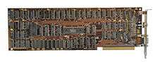
The Color Graphics Adapter (CGA), originally also called the Color/Graphics Adapter or IBM Color/Graphics Monitor Adapter,[1] introduced in 1981, was IBM's first graphics card and first color display card for the IBM PC. For this reason, it also became that computer's first color computer display standard.
The standard IBM CGA graphics card was equipped with 16 kilobytes of video memory and could be connected either to a dedicated direct-drive CRT monitor using a 4-bit digital (TTL) "RGBI"[2] interface, such as the IBM 5153 color display, or to an NTSC-compatible television or composite video monitor via an RCA connector.[3] The RCA connector provided only baseband video, so to connect the CGA card to a standard television set required a separate RF modulator unless the TV had an RCA jack though with the former combined with an amplifier sometimes was more practical since one could then hook up an antenna to the amplifier and get wireless video .[4]
Built around the Motorola MC6845 display controller,[5] the CGA card featured several graphics and text modes. The highest display resolution of any mode was 640×200, and the highest color depth supported was 4-bit (16 colors).
Output capabilities
CGA supports:
- 320×200 in 4 colors from a 16 color hardware palette. Pixel aspect ratio of 1:1.2.
- 640×200 in 2 colors. Pixel aspect ratio of 1:2.4
(The pixel ratio stems from rendering said amount of pixels on a 4:3 screen, a monitor ratio typical of that time.)
Text modes:
- 40×25 with 8×8 pixel font (effective resolution of 320×200)
- 80×25 with 8×8 pixel font (effective resolution of 640×200)
Extended graphics modes:
- 160×100 16 color mode
- Artifact colors using a NTSC monitor (16 colors from more than 100 possible)
IBM intended that CGA be compatible with a home television set. The 40x25 text and 320x200 graphics modes are usable with a television, and the 80x25 text and 640x200 graphics modes are intended for a monitor.[5]
 CGA 320x200 in 4 colors palette 0
 CGA 320x200 in 4 colors palette 1
 CGA 320x200 in 4 colors 3rd palette
 CGA 640×200 in 2 colors
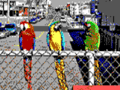 CGA 160×100 16 color mode
 A partial Mandelbrot set rendered in CGA palette 1
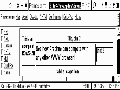 Screenshot of Arachne displaying its embedded frames and tables test pages in CGA 640x200 mode
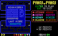
 PakuPaku in 160×100 16 color mode
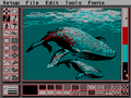 PCPaint in 320x200 3rd palette low intensity, showing a typical low resolution interface. Note the use of dithering to overcome the CGA palette limitations.
 SimCity in 640x200 monochrome. Note the use of dithering to simulate gray tones and non-square pixel ratio that deforms the fonts.
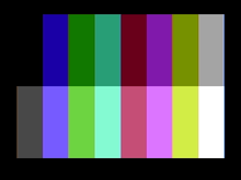
Color palette
Despite varying bit depths among the CGA graphics modes (see below), CGA processes colors in its palette in four bits, yielding 24 = 16 different colors. The four color bits are arranged according to the RGBI color model: the lower three bits represent red, green, and blue color components; a fourth "intensifier" bit, when set, increases the brightness of all three color components (red, green, and blue).[6] In graphics modes, colors are set per-pixel; in text modes, colors are set per-character, with an independent foreground and background color for each character.
| Full CGA 16-color palette | |||
|---|---|---|---|
| 0 | black #000000 |
8 | gray #555555 |
| 1 | blue #0000AA |
9 | light blue #5555FF |
| 2 | green #00AA00 |
10 | light green #55FF55 |
| 3 | cyan #00AAAA |
11 | light cyan #55FFFF |
| 4 | red #AA0000 |
12 | light red #FF5555 |
| 5 | magenta #AA00AA |
13 | light magenta #FF55FF |
| 6 | brown #AA5500 |
14 | yellow #FFFF55 |
| 7 | light gray #AAAAAA |
15 | white (high intensity) #FFFFFF |
With an RGBI monitor
These four bits are passed on unmodified to the DE-9 connector at the back of the card, leaving all color processing to the RGBI monitor connected to it. With respect to the RGBI color model described above, the monitor would use approximately the following formula to process the digital four-bit color number to analog voltages ranging from 0.0 to 1.0:
red   := 2/3×(colorNumber & 4)/4 + 1/3×(colorNumber & 8)/8
green := 2/3×(colorNumber & 2)/2 + 1/3×(colorNumber & 8)/8
blue  := 2/3×(colorNumber & 1)/1 + 1/3×(colorNumber & 8)/8
| Dark Yellow | |
|---|---|
| 6 | #AAAA00 |
Color 6 is treated differently; when using the formula above, color 6 would become dark yellow, as seen to the left, but in order to achieve a more pleasing brown tone, special circuitry in most RGBI monitors, including the IBM 5153 color display,[7] makes an exception for color 6 and changes its hue from dark yellow to brown by halving the analogue green signal's amplitude:
if colorNumber = 6 then green := green / 2
It is this "RGBI with tweaked brown" palette, shown in the complete palette to the right, that all later PC graphics standards such as EGA and VGA have retained for compatibility as a power-on default setting of their internal palette registers and/or DAC registers.
With a composite color monitor/television set
For the composite output, these four-bit color numbers are encoded by the CGA's onboard hardware into an NTSC-compatible signal fed to the card's RCA output jack. For cost reasons, this is not done using an RGB-to-YIQ converter as called for by the NTSC standard, but by a series of flip-flops and delay lines.[8][9] Consequently, the hues seen are lacking in purity; notably, both cyan and yellow have a greenish tint, and color 6 again looks dark yellow instead of brown. The relative luminances of the colors produced by the composite color-generating circuit differ between CGA revisions: they are identical for colors 1-6 and 9-14 with early CGAs produced until 1983,[10] and are different for later CGAs due to the addition of additional resistors.[11]
RGBI monitor availability
When the CGA was introduced in 1981, IBM did not offer an RGBI monitor.[12] Instead, customers were supposed to use the RCA output with an RF modulator (that they obtained separately, from a third party) to connect the CGA to their television set.[13] The IBM 5153 Personal Computer Color Display would not be introduced until March 1983.[14] Resulting from the lack of available RGBI monitors in 1981 and 1982, many users would use simpler RGB monitors (without provisions for the "intensifier" bit), reducing the number of available colors to eight, and displaying both colors 6 and 14 as yellow.[12] This is relevant insofar as if an application or game programmer used either one of these configurations, they will have expected color 6 to look dark yellow instead of brown.
Standard text modes
CGA offers four BIOS text modes (called alphanumeric modes in IBM's documentation):
- 40×25 characters in up to 16 colors. Each character is a pattern of 8×8 dots. The effective screen resolution in this mode is 320×200 pixels (a pixel aspect ratio of 1:1.2), though individual pixels cannot be addressed independently. The choice of patterns for any location is thus limited to one of the 256 available characters, the patterns for which are stored in a ROM chip on the card itself. The display font in text mode (the hardware code page 437 character set) is therefore fixed and cannot be changed (although when using the original IBM CGA, it is possible to select one of two different fonts—normal or thin—by changing a jumper. Many clones didn't offer this possibility). The card has sufficient video RAM for eight different text pages in this mode.
BIOS Modes 0 & 1 select 40 column text modes. The difference between these two modes can only be seen on a composite monitor; mode 0 disables the color burst, making colors appear in grayscale. Mode 1 enables the color burst, allowing for color. Mode 0 and Mode 1 are functionally identical on RGB monitors and on later adapters that emulate CGA without supporting composite color output.
- 80×25 characters in up to 16 colors. Each character is again an 8×8 dot pattern (the same character set is used as for 40×25), in a pixel aspect ratio of 1:2.4. The effective screen resolution of this mode is 640×200 pixels. Again, the pixels cannot be individually addressed. Since there are twice as many characters on the screen in this mode, the card has enough video RAM for just four different text pages.
BIOS Modes 2 & 3 select 80 column text modes. As with the 40-column text modes, Mode 2 disables the color burst in the composite signal and Mode 3 enables it.
In every text mode, each character has a background and a foreground color—e.g. red on yellow text for one character, white on black for the next, etc. While the same 4-bit nybble value used for the foreground color would normally allow all 16 colors to be used for the background color, the most significant bit of the background nybble is alternatively used to denote whether or not the character should blink (a hardware effect offered by CGA independent of the CPU). When a character is blinking, its foreground dots alternate between the foreground and background color, so that the during the blink off period, the character cell is filled with the background color (exactly like a space character).[15] All blinking characters on the screen blink in sync. The blinking attribute effect is enabled by default and the high-intensity background effect is disabled; disabling blinking is the only way to freely choose the latter eight-color indexes (8-15) for the background color.
Notably, the GW-BASIC and, later, Microsoft QBASIC (a lesser derivative of Microsoft QuickBASIC) programming language interpreters included with MS-DOS (which was the de facto PC OS while the CGA was popular) supported all the text modes of the CGA with full color control, but did not provide a normal means through the BASIC language to switch the CGA from blink mode to 16-background-color mode, though it would be possible by directly programming the hardware registers using the OUT statement of the BASIC language. In BASIC, foreground text color numbers 16-31 are the blinking versions of colors 0-15, respectively, but background colors 8-15 are identical to colors 0-7 respectively.
Standard graphics modes
CGA offers two commonly-used BIOS graphics modes (sometimes called all points addressable by IBM):
- 320x200 pixels, as with the 40x25 text mode. In the graphics mode, however, each pixel can be addressed independently. The tradeoff is that only four colors can be displayed at a time. Also, only one of the four colors can be freely chosen from the 16 CGA colors—there are only two official palettes for this mode, differing in the presence or absence of the blue color component:
| |||||||||||||||
|
- Magenta, cyan, white and background color (any of the 16 colors, black by default).
- Red, green, brown/yellow and background color (any of the 16 colors, black by default).
- By setting the high-intensity bit, brighter versions of these modes can be accessed.
- The 1:1.2 pixel aspect ratio needs to be taken into account when drawing large geometrical shapes on the screen.
BIOS Modes 4 & 5 set up the 320x200 graphics modes. Similar to the text modes, Mode 4 enables the composite color burst bit, Mode 5 disables it. Unlike the text modes, disabling the composite color burst bit (which setting Mode 5 does) in 320x200 affects the colors displayed on an RGB monitor with the IBM CGA card and true compatibles (see below.)
- 640x200 pixels, as with the 80x25 text mode. All pixels can be addressed independently. This mode is monochrome with a pixel aspect ratio of 1:2.4. By default the colors are black and bright white, but the foreground color can be changed to any other color of the CGA palette. This can be done at runtime without refreshing the screen. The background color cannot be changed from black on a true IBM CGA card.
BIOS Mode 6 sets up the 640x200 graphics mode. This mode disables the composite color burst signal by default. The BIOS does not provide an option to turn the color burst on in 640x200 mode, and the user must write directly to the mode control register to enable it.
In text mode, font bitmap data comes from the character ROM on the card, which is only available to the card itself. In graphics modes, text output by the BIOS uses two separate tables. The first half of the character set (characters numbered 0 through 127, corresponding to 7-bit ASCII with some added graphical symbols) is supplied by a table in the BIOS ROM chip on the computer's mainboard at the fixed address F000:FA6E (the table is still present at this location even in modern PC BIOSes; unlike the font ROM on the CGA card itself that is used for the text modes, this table provides only the "thick" font shapes, not the "thin" ones). The second half of the set (characters numbered 128 through 255, corresponding to the international, block-graphics and mathematics characters) is supplied by the location pointed to by interrupt vector 1F (the vector itself is found at memory address 0000:007C; this is not in fact a real interrupt vector, since the vector does not point to executable machine code, as real interrupt vectors on the PC's Intel 8086 CPU do). The second half of the character set is ordinarily absent (the vector 1F does not point to actual font data), and trying to display it will result in garbage or blank characters. The character data may be placed into memory manually by the user, or by a utility such as GRAFTABL.
Further graphics modes and tweaks
| # | 3rd palette | 3rd Palette in high intensity |
|---|---|---|
| 0 | default | default |
| 1 | 3 — cyan | 11 — light cyan |
| 2 | 4 — red | 12 — light red |
| 3 | 7 — light gray | 15 — white (high intensity) |
A number of official and unofficial features exist that can be exploited to achieve special effects.
- In 320×200 graphics mode, the background color (which also affects the border color), which defaults to black on mode initialization, can be changed to any of the other 15 colors of the CGA palette. This allows for some variation, as well as flashing effects, as the background color can be changed without having to redraw the screen (i.e. without changing the contents of the video RAM.)
- In 640×200 graphics mode, the foreground color can be changed from its usual white to any of the other 15 colors. The background and border cannot be changed from black.
- In text mode, the border color (displayed outside the regular display area—into the overscan area) can be changed from its usual black to any of the other 15 colors.
- A third 320×200 4-color palette is achieved by disabling the composite color burst bit while in graphics mode. This is what IBM BIOS Mode 5 does, as described above. This switches the current color palette to red, cyan, white and the background color. The intense versions of these colors can also be used and the background color may be changed, but the palette cannot be switched to official palettes 0 or 1 without enabling the composite color signal again. As such, it can only be seen on RGB monitors and will simply appear in grayscale on composite displays. This palette was often used by games because it looked more attractive than the cyan/magenta/white colors. Notably, it is not mentioned in the IBM Technical Reference manual, and some CGA clones may not support it.
- Through precision timing, it is possible to switch to another palette while the screen being scanned (drawn), allowing the use of any one of the six palettes per scanline. The best example of this in use is the game California Games[16] when run on a stock 4.77 MHz 8088. (Running it on a faster computer does not produce the effect, as the method the programmers used to switch palettes at predetermined locations is extremely sensitive to machine speed.) The same can be done with the background color, to create the river and road in Frogger.[17] Another documented example of the technique is in Atarisoft's port of Jungle Hunt to the PC.
- Additional colors are often approximated using dithering, although the low resolution makes it very apparent. In particular, many Sierra games use palette 1 at low intensity and dark blue as the background color. This gives it the three primary RGB colors to work with (as well as brown).
Some of these above tweaks can even be combined. Examples can be found in several games.[18] Most software titles did not use these possibilities, but there were a few impressive exceptions.
160×100 16 color mode
Technically, this mode is not a graphics mode, but a tweak of the 80×25 text mode. The character cell height register is changed to display only two lines per character cell instead of the normal eight lines. This quadruples the number of text rows displayed from 25 to 100. These "tightly squeezed" text characters are not full characters. The system only displays their top two lines of pixels (eight each) before moving on to the next row.
| |
Character 221. |
| |
221 with blue text and red background color. |
| |
221 with red text and blue background color. |
| |
Character 222. |
Character 221 of code page 437 consists of a box occupying the entire left half of the character matrix. (Character 222 consists of a box occupying the entire right half.)
Because each character can be assigned different foreground and background colors, it can be colored (for example) blue on the left (foreground color) and bright red on the right (background color). This can be reversed by swapping the foreground and background colors.
Using either character 221 or 222, each half of each truncated character cell can thus be treated as an individual pixel—making 160 horizontal pixels available per line. Thus, 160×100 pixels at 16 colors, with an aspect ratio of 1:1.2, are possible.
Although a roundabout way of achieving 16-color graphics display, this works quite well and the mode is even mentioned (although not explained) in IBM's official hardware documentation.[19]
More detail can be achieved in this mode by using other characters, combining ASCII art with the aforesaid technique.
Because the CGA has 16 KiB (16384 bytes) of graphics memory, not 16000, it is just as easy to set the number of lines in this mode to 102 instead of 100 for a resolution of 160×102 (16320 pixels). This uses extra video memory that is normally unused. However, most games did not do this, perhaps out of fear it would only work on some monitors but not others.
The same text cell height reduction technique can also be used with the 40×25 text mode. This only made sense when using ASCII art, because without it the resulting resolution would only have been 80×100.[20][21][22]
Special effects on composite color monitors
Using the NTSC TV-out instead of an RGBI monitor not only made for less attractive colors, as described above, but as is common with NTSC composite video, the separation between luminance and chrominance is far from perfect, yielding cross-color artifacts, or color "smearing". This is especially a problem with 80-column text:
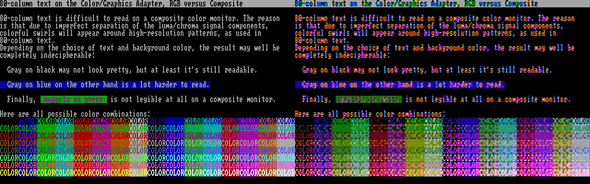
It is for this reason that each of the text and graphics modes described above exists twice: once as the normal "color" version and once as a "monochrome" version; the "monochrome" version of each mode would turn off the NTSC color decoding in the viewing monitor completely, resulting in a black-and-white picture, but also no color bleeding, hence, a sharper picture. On RGBI monitors, the two versions of each mode are identical, with the exception of the 320x200 graphics mode, where the "monochrome" version produces the third palette, as described above.
However, programmers soon found out that this flaw could be turned into an asset, as distinct patterns of high-resolution dots would "smear" into consistent areas of solid colors, thus allowing the display of completely new artifact colors. Both the standard 320×200 four-color and the 640×200 color-on-black graphics modes could be used with this technique.
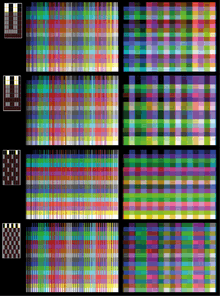
Internal operation
Direct colors are the normal 16 colors as described above under "The CGA color palette".
Artifact colors are seen because the composite monitor's NTSC chroma decoder misinterprets some of the luminance information as color, as stated before. By carefully placing pixels in appropriate patterns, the skilled programmer produces particular cross-color artifacts yielding the desired color; either from purely black-and-white pixels in 640×200 mode, or resulting from a combination of direct and artifact colors in 320×200 mode, as seen in these pictures.
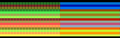 320×200 palette 0
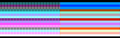 320×200 palette 1
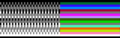 640×200
Thus, with the choice of 320×200 vs. 640×200 mode, the choice of palette (1 or 2) and the freely-selectable color 0 in 320×200 modes (see above), plus the ability to set the foreground color in 640×200 mode freely, each one of these parameters results in a different set of artifact colors, making for a total gamut of over 100 colors, of which 16 can be displayed at the same time.
Later demonstrations by enthusiasts have increased the maximum number of colors the CGA is known to produce in a single image to approximately a thousand. Aside of artifacting, this technique involves the text mode tweak which quadruples its rows, thus offering the benefit of 16 foreground and 16 background colors. Certain ASCII characters such as U and ‼ are then used to produce the necessary patterns, which result in non-dithered images with an effective resolution of 80×100 on a composite monitor.[23]
Availability and caveats
The 320×200 variant of this technique (see above) is how the standard BIOS-supported graphics mode looks on a composite color monitor. The 640×200 variant, however, requires modifying a bit (color burst disable) directly in the CGA's hardware registers, as a result, it is usually referred to as a separate "mode", often just as "the" composite color mode, since its more distinctive set of artifact colors led it to being more commonly used than the 320×200 variant.
Being completely dependent on the NTSC encoding/decoding process, composite color artifacting is not available on an RGBI monitor, nor is it emulated by EGA, VGA or contemporary graphics adapters.
The modern, games-centric PC emulator DOSBox includes a CGA mode, which can emulate a composite monitor (in graphics modes). As of December 2012, the latest official version will emulate the more common 640×200 composite mode and its set of 16 artifact colors; support for the more complex 320×200 variant has been added to the DOSBox codebase for the next official build.
Resolution and usage
Composite artifacting, whether used intentionally or as an unwanted artifact, reduces the effective horizontal resolution to a minimum of 160 pixels, more for black-on-white or white-on-black text, without changing the vertical resolution. The resulting composite video display with "artifacted" colors was thus sometimes described as a 160x200/16-color "mode", though technically it was a method, not a mode.
The low resolution of this composite color artifacting method led to it being used almost exclusively in games. Many of the more high-profile titles optionally, sometimes exclusively, offering graphics optimized for composite color monitors. Ultima II, the first game in the game series to be ported to IBM PC, used CGA composite graphics. King's Quest I was innovative in its use of 16-color graphics on the PC, PCjr and Tandy 1000; even CGA owners could enjoy the 16-color graphics by using a composite color monitor or television, thanks to programmers exploiting the inaccuracies of composite NTSC chroma decoding. Selecting 'RGB mode' at the title screen would instead result in the usual CGA graphics mode limited to 4 colors. In this mode, dithering was employed to simulate extra colors.
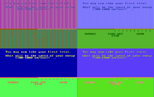 Microsoft Decathlon - Top: Game in composite mode, Bottom: Game in RGB mode, Left: with RGB monitor, Right: with composite monitor
 King's Quest -Top: Game in composite mode, Bottom: Game in RGB mode, Left: with RGB monitor, Right: with composite monitor
 Ultima II - Left: with RGB monitor, Right: with composite monitor
High color depth
By taking advantage of the color smearing, the NTSC color clock and a method similar to that used in the 16 color mode, it's possible to display over 16 colors in composite monitors.
The NTSC color clock has 160 cycles per scanline, which means that in 40 column mode each pixel occupies half a cycle, while in 80 column mode each pixel uses a quarter of a cycle. Limiting the character display to the upper or upper two scanlines, and taking advantage of the pixel arrangement in certain characters of the codepage 437, it is possible to display up to 1024 colors.[24]
Limitations, bugs and errata.
Video timing on the CGA is provided by the Motorola 6845 video controller. This integrated circuit was originally designed only for character-based alphanumeric (text) displays and can only address a maximum of 128 character rows. To realize graphics modes with 200 scanlines on the CGA, the MC6845 is programmed with 100 character rows per picture and two scanlines per character row. Because the video memory address output by the MC6845 is identical for each scanline within a character row, the CGA must use the MC6845's "row address" output (i.e. the scanline within the character row) as an additional address bit to fetch raster data from video memory.[25] This implies that unless the size of a single scanline's raster data is a power of two, raster data can not be laid out continuously in video memory. Instead, graphics modes on the CGA first put only the even-numbered scanlines continuously in a first block of video memory, then a second block of odd-numbered scanlines starting at video memory position 8,192. This arrangement results in additional overhead in graphics modes for software that manipulates video memory.
Even though the MC6845 video controller can provide the timing for interlaced video, the CGA's circuitry aligns the synchronization signals in such a way that scanning is always progressive. Therefore, it is impossible to double the vertical resolution to 400 scanlines using a standard 15 kHz monitor.
The higher bandwidth used by 80-column text mode results in random short horizontal lines appearing onscreen (known as "snow") if a program writes directly to video memory. The BIOS avoids the problem by only accessing the memory during horizontal retrace, or by temporarily turning off the output during scrolling; while causing the display to blink, IBM decided that doing so was better than snow.[5] The "snow" problem does not occur on any other video adapter, or on most CGA clones.
In the 80-column text mode, the pixel clock is doubled, and all the synchronization signals are output for twice the number of clock cycles in order to last for their proper duration. The composite output's color burst signal circuit is an exception: because it still outputs the same number of cycles now at twice the clock rate, the color burst signal produced is too short for most monitors, yielding no or unstable color. Hence, IBM documentation lists the 80-column text mode as a "feature" only for RGBI and black-and-white composite monitors.[26] Stable color can still be achieved by setting the border color to brown, which happens to produce a phase identical to the correct color burst signal and serves as a substitute for it.
Software support
CGA was widely supported in PC software up until the 1990s. Some of the software that supported the board was:
- Windows 3.0 (and earlier versions)
- OS/2 1.1 (and earlier versions)
- Graphics Environment Manager (GEM)
Competing adapters
BYTE in January 1982 described the output from CGA as "very good—slightly better than color graphics on existing microcomputers".[12] CGA had two main competitors:
- For business and word processing use, IBM announced its Monochrome Display Adapter (MDA) at the same time as CGA. MDA was much more popular than CGA at first;[27] it produced a higher resolution text display in 80×25 mode, rendering each character in a box of 9×14 pixels, of which 7×11 were the character itself. This produced sharper and more clearly separated characters than the CGA's 8×8 dots text character matrix allowed. Because of this, MDA was the preferred choice for business use. Also, IBM initially manufactured the MDA card as a printer port/MDA combo card. This meant that users wishing to connect printers to their original IBM PC would have to pay for the MDA card anyway (initially $335), while the CGA card (initially $300) could be left out to save money. While including the CGA card and connecting an existing TV set for use as a monitor allowed users to forgo the purchase of a monitor, this was not significantly cheaper than buying a monochrome monitor (initially $345) and leaving out the CGA card. Also, 80-column text was almost unusable on color composite displays, and the IBM model 5153 CGA color video display that was required to fully exploit the CGA card's capabilities was even more expensive. Since a great many PCs were sold to businesses, the sharp, high-resolution monochrome text was more desirable for running applications.
- In 1982, the non-IBM Hercules Graphics Card (HGC) was introduced, the first third-party video card for the PC. In addition to an MDA-compatible text mode, it offered a monochrome graphics mode. With a resolution of 720×348 pixels, it had a higher resolution than that produced by CGA. The Hercules' combination of sharp monochrome text and graphics capabilities made it ideal for running software such as Lotus 123 that supported business graphics. Some games also had Hercules support, and most others could be made to work with HGC via SimCGA, a TSR which would reformat the CGA graphics memory to HGC format in the background.
Other alternatives:
- The IBM PCjr (1984) and the compatible Tandy 1000 (1985) featured onboard "extended CGA" video hardware that extended video RAM beyond 16 kB, thus allowing 16 colors at 320×200 resolution and four colors at 640×200 resolution (later Tandys also had a 640×200 mode with 16 colors). Because the Tandy 1000 long outlived the PCjr, the video modes became known as "Tandy Graphics Adapter" or "TGA", and were very popular for games during the 1980s. Similar but less widely used was the Plantronics Colorplus.
- In 1984, IBM also introduced the Professional Graphics Controller, a high-end graphics solution intended for e.g. CAD applications. It was mostly backwards compatible with CGA. The PGC did not see widespread adoption due to its $4,000 price tag, and was discontinued in 1987.
- Paradise Systems introduced in 1984 the first successful CGA-compatible card for MDA monitors. It displayed CGA's 16 colors in shades of monochrome. Because it was hardware-compatible with CGA, the Paradise card did not need special software support or additional drivers.[28]
- Another extension in some CGA-compatible chipsets (including those in the Olivetti M24, AT&T 6300, the DEC VAXmate, and some Compaq and Toshiba portables) is a doubled vertical resolution. This gives a higher quality 8×16 text display and an additional 640×400 graphics mode.
The CGA card was succeeded in the consumer space by IBM's Enhanced Graphics Adapter (EGA) card, which supports most of CGA's modes and adds an additional resolution (640×350) as well as a software-selectable palette of 16 colors out of 64 in both text and graphics modes. Along with this move, the price of the older CGA card was lowered considerably; it became an attractive low-cost option and was soon adopted by the new PC cloning companies as well. Entry-level non-AT PCs with CGA graphics sold very well during the next few years, and consequently there were many games released for such systems, despite CGA's limitations. CGA's popularity started to wane after VGA became IBM's high-level standard and EGA the entry-level standard in 1987. However, most software made up to 1990 supported it.
Specifications
Connector
The Color Graphics Adapter uses a standard DE-9 connector for direct-drive video (to an RGBI monitor). The connector on the card is female and the one on the monitor cable is male.
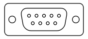
| Pin | Function |
|---|---|
| 1 | Ground |
| 2 | Ground |
| 3 | Red |
| 4 | Green |
| 5 | Blue |
| 6 | Intensity |
| 7 | Reserved |
| 8 | Horizontal Sync |
| 9 | Vertical Sync |
Signal
| Type | Digital, TTL |
|---|---|
| Resolution | 640h × 200v, 320h × 200v |
| H-freq | 15.75 kHz |
| V-freq | 60 Hz |
| Colors | 16 |
See also
- RGB color model
- Graphics card
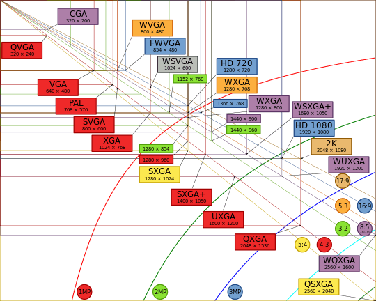
- Graphic display resolutions
- Graphics processing unit
- List of display interfaces
- List of 8-bit computer hardware palettes – CGA section
- Code page 437
- List of defunct graphics chips and card companies
References
- ↑ ; cf. section 1-133, "Color/Graphics Adapter", page 143 of ibm_techref_v202_1.pdf
- ↑ Red, Green, Blue, Intensity
- ↑ A. Kumar (2002). Encyclopaedia of Management of Computer Hardware. Anmol Publications. p. 1050. ISBN 978-81-261-1030-8.
- ↑ (There was also a connector on the original IBM CGA cards for an add-on RF modulator unit installed inside the computer case, but no such device was offered by IBM, and it would have had to provide its own output connector separate from the ones on the CGA itself.)
- 1 2 3 Bradley, David J. (September 1990). "The Creation of the IBM PC". BYTE. pp. 414–420. Retrieved 2 April 2016.
- ↑ The color brown, represented by R=1, G=1, B=0, I=0, is an exception; whereas a straight interpretation of these bit values would resolve this color as dark yellow, the intensity of the green component is halved, to produce brown, for only this one 4-bit value. See this page for details. This special RGBI interpretation for brown is performed in the monitor; the IBM 5153 monitor designed for the CGA performs it, but some early third-party monitors did not.
- ↑ International Business Machines Corporation (1983): IBM Personal Computer XT Technical Reference Manual, pages D-42 to D-43.
- ↑ Dean et al. (1984): Composite video color signal generation from digital color signals. U.S. Patent #4,442,428
- ↑ International Business Machines Corporation (1983): IBM Personal Computer XT Technical Reference Manual, page D-40.
- ↑ IBM Personal Computer (PDF) (Technical Reference). IBM Personal Computer Hardware Reference Library (revised ed.). April 1983. p. D-50.
- ↑ IBM Color/Graphics Monitor Adapter (PDF) (Technical Reference). IBM Options and Adapters. p. 32.
- 1 2 3 Williams, Gregg (January 1982). "A Closer Look at the IBM Personal Computer". BYTE. p. 36. Retrieved 19 October 2013.
- ↑ International Business Machines Corporation (1982): You & Your IBM Personal Computer. Sales Brochure, page 4.
- ↑ International Business Machines Corporation (1983): Announcement Letter Number 183-002 - IBM COLOR DISPLAY, 5153. Dated February 4, 1983. http://www-01.ibm.com/common/ssi/ShowDoc.wss?docURL=/common/ssi/rep_ca/2/897/ENUS183-002/index.html&lang=en&request_locale=en
- ↑ As a consequence of this, the blink bit has no effect on a space character. The same is true of any character that has the same color for its foreground and background, as such a character also always appears the same as a blank space.
- ↑ mobygames.com
- ↑ mobygames.com
- ↑ mobygames.com
- ↑ cf. http://vintageibm.net/yahoo_site_admin/assets/docs/techrefv202.zip , section/page 1-142, "Color/Graphics Adapter", page 152 of ibm_techref_v202_1.pdf
- ↑ oldskool.org
- ↑ oldskool.org
- ↑ oldskool.org
- ↑ "CGA in 1024 Colors - a New Mode: the Illustrated Guide.". A blog entry by the creators of the demo "8088 MPH" explaining this technique.
- ↑ Viler (2015-04-15). "8088 MPH: CGA in 1024 Colors - a New Mode: the Illustrated Guide". 8088 MPH. Retrieved 2016-10-18.
- ↑ IBM Enhanced Graphics Adapter (PDF) (Technical Reference). IBM Options and Adapters. August 2, 1984. p. 41.
- ↑ IBM Color/Graphics Monitor Adapter (PDF) (Technical Reference). IBM Options and Adapters. p. 7.
- ↑ Curran, Lawrence J.; Shuford, Richard S. (November 1983). "IBM's Estridge". BYTE. pp. 88–97. Retrieved 19 March 2016.
- ↑ Stark, Craig L. (1984-10-02). "Paradise Graphics Card: It's Easier Being Green". PC Magazine. p. 59. Retrieved 25 October 2013.
- Notes
- IBM PC-Compatible CGA Video Reference – includes technical details
- CGA monitor calibration – Technical information on the IBM 5153 monitor's color decoding and calibration
- IBM Personal Computer Hardware Library: Technical Reference (Revised edition, 1983)
- This article was originally based on material from the Free On-line Dictionary of Computing.
External links
| Wikimedia Commons has media related to CGA. |
- Colour Graphics Adapter Notes
- Games with CGA Graphics
- Representative screenshots of CGA games
- User Friendly thread on the use of CGA