MOS Technology VIC-II
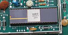
The VIC-II (Video Interface Chip II), specifically known as the MOS Technology 6567/8562/8564 (NTSC versions), 6569/8565/8566 (PAL), is the microchip tasked with generating Y/C video signals (combined to composite video in the RF modulator) and DRAM refresh signals in the Commodore 64 and C128 home computers.
Succeeding MOS's original VIC (used in the VIC-20), the VIC-II was one of the two chips mainly responsible for the C64's success (the other chip being the 6581 SID).
Development history
The VIC-II chip was designed primarily by Al Charpentier and Charles Winterble at MOS Technology, Inc. as a successor to the MOS Technology 6560 "VIC". The team at MOS Technology had previously failed to produce two graphics chips named MOS Technology 6562 for the Commodore TOI computer, and MOS Technology 6564 for the Color PET, due to memory speed constraints.[1]
In order to construct the VIC-II, Charpentier and Winterble made a market survey of current home computers and video games, listing up the current features, and what features they wanted to have in the VIC-II. The idea of adding sprites came from the Texas Instruments TI-99/4A computer and its TMS9918 graphics coprocessor. The idea to support collision detection came from the Mattel Intellivision. The Atari 800 was also mined for desired features.[2][3] About 3/4 of the chip surface is used for the sprite functionality.[4]
The chip was partly laid out using electronic design automation tools from Applicon (now a part of UGS Corp.), and partly laid out manually on vellum paper. The design was partly debugged by fabricating chips containing small subsets of the design, which could then be tested separately. This was easy since MOS Technology had both its research and development lab and semiconductor plant at the same location.[5] The chip was developed in 5 micrometer technology.[2]
The work on the VIC-II was completed in November 1981 while Robert Yannes was simultaneously working on the SID chip. Both chips, like the Commodore 64, were finished in time for the Consumer Electronics Show in the first weekend of January 1982.[6]
VIC-II features
- 16 kB address space for screen, character and sprite memory
- 320 × 200 pixels video resolution (160 × 200 in multi-color mode)
- 40 × 25 characters text resolution
- Three character display modes and two bitmap modes
- 16 colors
- Concurrent handling of 8 sprites per scanline, each of 24 × 21 pixels (12 × 21 multicolor)
- Raster interrupt (see details, below)
- Smooth scrolling
- Independent dynamic RAM refresh
- Bus mastering for a 6502-style system bus; CPU and VIC-II accessing the bus during alternating half-clock cycles (the VIC-II will halt the CPU when it needs extra cycles)
Technical details
Note that below register addresses are stated as seen by CPU in a C64. To yield the register numbers as usually given in data sheets (i. e. starting with 0), the leading "D0" should be omitted.
Programming
The VIC-II is programmed by manipulating its 47 control registers (up from 16 in the VIC), memory mapped to the range $D000–$D02E in the C64 address space. Of all these registers, 34 deal exclusively with sprite control (sprites being called MOBs, from "Movable Object Blocks", in the VIC-II documentation). Like its predecessor, the VIC-II handles light pen input, and with help from the C64's standard character ROM, provided the original PETSCII character set from 1977 on a similarly dimensioned display as the 40-column PET series.
By reloading the VIC-II's control registers via machine code hooked into the raster interrupt routine (the scanline interrupt), one can program the chip to generate significantly more than 8 concurrent sprites (a process known as sprite multiplexing), and generally give every program-defined slice of the screen different scrolling, resolution and color properties. The hardware limitation of 8 sprites per scanline could be increased further by letting the sprites flicker rapidly on and off. Mastery of the raster interrupt was essential in order to unleash the VIC-II's capabilities. Many demos and some later games would establish a fixed "lock-step" between the CPU and the VIC-II so that the VIC registers could be manipulated at exactly the right moment.
Character graphics
Most programming of the VIC-II is done with programmable character mode, and this is what the vast majority of C64/C128 games use. In power-on default mode, the character ROM is used which contains the PETSCII set. Normally, it can be seen only by the VIC-II and not the CPU. It is mapped into memory locations $3000–$3FFF and $B000-$BFFF and because of this, graphics data cannot be stored in those areas since the VIC-II will instead see the ROM there. By adjusting the bits in $01, the ROM can be mapped into $D000-$DFFF where it becomes visible to the CPU and programmers may copy characters from it to a different location as needed.
Up to 256 characters can be accessed by the VIC-II at once, although there is no limit to how many can be in memory provided they do not exceed the 16k video page. The default character set consists of two groups of 128 characters, the second group merely being an "inverse video" version of the first group.
Each character takes 8 bytes of memory to store. In addition to charsets, the VIC-II also uses 1k for its screen memory ($400–$7EF being the default). Color RAM is at $D800-$DBFF and cannot be moved from that location. It contains the values for Color 1 of each character.
In default hires character mode, the foreground of each character may be set individual per the color RAM. In multicolor character mode, Color 1 is limited to the first eight possible color values; the fourth bit is then used as a flag indicating if this character is to be displayed in hires or multicolor, thus making it possible to mix both types on one screen. Colors 2 and 3 are set by the registers at $D022 and $D023 and are global for all characters.
If Extended Background Color Mode is used, the upper two bits of the character code are used to select one of four background color registers. This allows four different background colors on the screen, but at the expense of only allowing 64 different characters instead of 256. Because this is fairly limiting, games seldom used it.
Bitmap mode
Adding an all-points-addressable bitmap mode was one of the Commodore design team's primary goals, as the VIC-I lacked such a feature. However, in order to use as little additional circuitry as possible, they organized it in the same manner as character mode, i.e. 8x8 and 4x8 tiles. Bitmap graphics require an 8k page for the pixel data and each byte corresponds to one row of eight or four pixels. The next byte is the row underneath it and after the 8th row, returning to the top of the next tile.
In hi-res bitmaps, screen RAM is used to hold the foreground and background colors of each tile (high and low nibble of each byte). This is the only VIC-II mode that does not make any use of the color RAM at $D800 or the background color register at $D021.
Multicolor bitmap mode allows three colors per tile (the fourth is the background color as set in $D021). Colors 1 and 2 are selected by the bits in screen RAM (same as hires bitmaps) and the third is from color RAM.
Despite the high level of color detail and all-points-addressable capabilities of bitmap mode, it is generally impractical for in-game graphics due to requiring a high amount of system resources (8k for the pixel data plus considerable more CPU cycles to modify each tile) and normally cannot be scrolled. Thus, it is normally only seen on loader and sometimes title screens. Dig Dug and Donkey Kong (Atarisoft) are two of the more notable examples of C64 games which utilize bitmap graphics.
Sprites
VIC-II sprites are either 24x21 monochrome or 12x21 multicolor. Similar to character graphics, the latter have one individual color for each sprite and two global ones. VIC-II has eight sprites, each of which uses 64 bytes of memory to store but, with certain limitations, in can display many more. Sprite multiplexing is a common method of getting more than eight on screen (although there still is a maximum of eight per scan line). The VIC-II scanline counters are polled until the desired point is reached on screen, after which the program quickly changes the sprite coordinates. This programming trick and other workarounds could result to over twenty sprites onscreen once. For a demo, though, the limit is considerably more flexible.
In theory the maximum number of different sprites visible at the same time is 256 (assuming the VIC-II's entire 16k page was filled). They are addressed by using a block number to refer to each sprite pattern in memory beginning with 0 and going to 255 ($FF) depending on their position in the video page. (if Page 2 is used, Block 0 would refer to the sprite stored at $4000 and Block 255 would be at $7FBF).
Each sprite may be double-sized vertically, horizontally or both. This does not make the sprite bigger (except visually) or add more pixels to the sprite, but merely upscales the existing pixels.
Because the horizontal position register for sprites is one byte and limited to a maximum value of 255, it could not cover the entire 320 pixels of the VIC-II's screen area, so an additional register called the Most Significant Byte Flag is provided for this.
$D01E and $D01F contain the Background and Sprite-to-Sprite Collision registers. The former is rarely used because it cannot provide information on the specific background object the sprite is touching.
$D01B contains the Sprite To Background priority register, which is used to govern whether a sprite moves behind or in front of background objects. When a sprite enters the same space as another sprite, the lower-numbered ones will always pass over the higher numbered ones.
Scrolling
In order to scroll a character screen, the VIC-II is set to 38-column and/or 24-line mode via the registers at $D011 and $D016. This creates an off-screen buffer where the row of characters to be scrolled is placed. By adjusting the scroll bits in the above-mentioned registers, one row may be moved on-screen after which it repeats unless a new row is put in the buffer. Color RAM is scrolled simultaneous with screen RAM and works the same way.
VIC-II scrolling is a relatively complicated, CPU intensive task, although it was not uncommon for C64 game programmers to cheat by designing graphics so that the color RAM can remain static. Another standard trick is to cover the bottom or top 25% of the screen with a score counter to reduce the amount of scrolling that has to be performed. Finally, it is usually necessary to use an extra 1k piece of RAM to write character data to and then "blit" it into the screen RAM to prevent screen tearing, although this cannot be done with color RAM.
Raster interrupts
Utilization of raster interrupts is an essential part of C64 game programming. In the computer's power-on default state, the first CIA chip generates an interrupt 60 times per second which sends the CPU to the kernel IRQ handler at $EA31. This acknowledges the CIA interrupt, updates the clock, scans the keyboard, and blinks the cursor in BASIC. Games normally disable this and instead set up the VIC-II to generate interrupts when a specific scanline is reached, which is necessary for split-screen scrolling and playing music. The game remaps the IRQ vector at $0314/$0315 to its raster handler which performs these functions and then optionally executes a JMP $EA31 instruction to return control to the kernel, provided that the game does not take over the machine and therefore doesn't want to apply kernel's interrupt routine.
Some games use only one IRQ; however, nested ones are more common and improve program stability. In this setup, the IRQ is remapped to the second routine and so forth for each one until the last one restores it to the address of the first IRQ. When nested IRQs are used, only one JMP $EA31 instruction is needed in the chain and the others can be ended with JMP $EA81, which simply goes to the end of the kernel handler.
The VIC-II may also generate a raster interrupt from the collision registers, but this feature is rarely used.
Memory mapping
The VIC-II has a 14-bit address bus and can use any of the four 16k segments of the C64's memory space for video data. To manage this, two additional address bits are contributed by port bits of CIA. $0000-$3FFF is the power-on default. The second segment ($4000–$7FFF) is typically the best choice for games as it is the only segment that is completely free RAM with no ROMs or I/O registers mapped into it. The fourth segment ($C000–$FFFF) is also a good choice, provided that machine language is used, as the kernel ROMs must be disabled to gain read access by the CPU. Note that graphics data may be freely stored underneath the BASIC ROM at $A000-$BFFF, the kernel ROM at $E000-$FFFF or I/O registers at $D000–$DFFF, since the VIC-II only sees RAM, regardless how the CPU memory mapping is adjusted; character ROM is visible only in the first and third segment. The screen RAM, bitmap page, sprites, and character sets must all occupy the same segment window (provided the CIA bits aren't changed by scanline interrupt).
Registers
The VIC-II has 47 read/write registers listed below:
| Register | Hexadecimal | Bit 7 | Bit 6 | Bit 5 | Bit 4 | Bit 3 | Bit 2 | Bit 1 | Bit 0 | Description |
|---|---|---|---|---|---|---|---|---|---|---|
| |
|
M0X | X Coordinate Sprite 0 | |||||||
| |
|
M0Y | Y Coordinate Sprite 0 | |||||||
| |
|
M1X | X Coordinate Sprite 1 | |||||||
| |
|
M1Y | Y Coordinate Sprite 1 | |||||||
| |
|
M2X | X Coordinate Sprite 2 | |||||||
| |
|
M2Y | Y Coordinate Sprite 2 | |||||||
| |
|
M3X | X Coordinate Sprite 3 | |||||||
| |
|
M3Y | Y Coordinate Sprite 3 | |||||||
| |
|
M4X | X Coordinate Sprite 4 | |||||||
| |
|
M4Y | Y Coordinate Sprite 4 | |||||||
| |
|
M5X | X Coordinate Sprite 5 | |||||||
| |
|
M5Y | Y Coordinate Sprite 5 | |||||||
| |
|
M6X | X Coordinate Sprite 6 | |||||||
| |
|
M6Y | Y Coordinate Sprite 6 | |||||||
| |
|
M7X | X Coordinate Sprite 7 | |||||||
| |
|
M7Y | Y Coordinate Sprite 7 | |||||||
| |
|
M7X8 | M6X8 | M5X8 | M4X8 | M3X8 | M2X8 | M1X8 | M0X8 | MSBs of X coordinates |
| |
|
RST8 | ECM | BMM | DEN | RSEL | YSCROLL | Control register 1 | ||
| |
|
RASTER | Raster counter | |||||||
| |
|
LPX | Light Pen X | |||||||
| |
|
LPY | Light Pen Y | |||||||
| |
|
M7E | M6E | M5E | M4E | M3E | M2E | M1E | M0E | Sprite enabled |
| |
|
- | - | RES | MCM | CSEL | XSCROLL | Control register 2 | ||
| |
|
M7YE | M6YE | M5YE | M4YE | M3YE | M2YE | M1YE | M0YE | Sprite Y expansion |
| |
|
VM13 | VM12 | VM11 | VM10 | CB13 | CB12 | CB11 | - | Memory pointers |
| |
|
IRQ | - | - | - | ILP | IMMC | IMBC | IRST | Interrupt register |
| |
|
- | - | - | - | ELP | EMMC | EMBC | ERST | Interrupt enabled |
| |
|
M7DP | M6DP | M5DP | M4DP | M3DP | M2DP | M1DP | M0DP | Sprite data priority |
| |
|
M7MC | M6MC | M5MC | M4MC | M3MC | M2MC | M1MC | M0MC | Sprite multicolor |
| |
|
M7XE | M6XE | M5XE | M4XE | M3XE | M2XE | M1XE | M0XE | Sprite X expansion |
| |
|
M7M | M6M | M5M | M4M | M3M | M2M | M1M | M0M | Sprite-sprite collision |
| |
|
M7D | M6D | M5D | M4D | M3D | M2D | M1D | M0D | Sprite-data collision |
| |
|
- | - | - | - | EC | Border color | |||
| |
|
- | - | - | - | B0C | Background color 0 | |||
| |
|
- | - | - | - | B1C | Background color 1 | |||
| |
|
- | - | - | - | B2C | Background color 2 | |||
| |
|
- | - | - | - | B3C | Background color 3 | |||
| |
|
- | - | - | - | MM0 | Sprite multicolor 0 | |||
| |
|
- | - | - | - | MM1 | Sprite multicolor 1 | |||
| |
|
- | - | - | - | M0C | Color sprite 0 | |||
| |
|
- | - | - | - | M1C | Color sprite 1 | |||
| |
|
- | - | - | - | M2C | Color sprite 2 | |||
| |
|
- | - | - | - | M3C | Color sprite 3 | |||
| |
|
- | - | - | - | M4C | Color sprite 4 | |||
| |
|
- | - | - | - | M5C | Color sprite 5 | |||
| |
|
- | - | - | - | M6C | Color sprite 6 | |||
| |
|
- | - | - | - | M7C | Color sprite 7 |
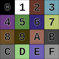
Colors
In multicolor character mode (160×200 pixels, which most games used) characters had 4×8 pixels (the characters were still approximately square since the pixels were double width) and 4 colors out of 16 colors. The 4th color was the same for the entire screen (the background color), while the other 3 could be set individually for every such 4×8 pixel area. Two colors were loaded from the active text screen, and the third was loaded from color RAM. Sprites in multicolor mode (12×21 pixels) had three colors: two shared among all sprites and one individual. The artist had to pick shared colors such that the combination with individual colors led to a colorful impression. Some games reloaded shared colors during the raster interrupt; for example, the game Turrican II's underwater area (which was vertically distinct) had different colors. Others, such as Epyx's Summer Games and COMPUTE!'s Gazette's Basketball Sam & Ed, overlaid two high-resolution sprites to allow two foreground colors to be used without sacrificing horizontal resolution . Of course, this technique reduced the number of available sprites by half.
On PAL C64s, the PAL delay line in the monitor or TV which averages the color hue, but not the brightness, of consecutive screen lines can be used to create seven nonstandard colors by alternating screen lines showing two colors of identical brightness. There are seven such pairs of colors in the VIC chip.
The C64's team did not spend much time on mathematically computing the 16 color palette. Robert Yannes, who was involved with the development of the VIC-II, said:
I'm afraid that not nearly as much effort went into the color selection as you think. Since we had total control over hue, saturation and luminance, we picked colors that we liked. In order to save space on the chip, though, many of the colors were simply the opposite side of the color wheel from ones that we picked. This allowed us to reuse the existing resistor values, rather than having a completely unique set for each color.[7]
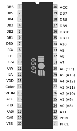
The VIC-IIe
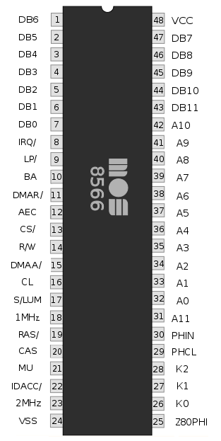
The 8564/8566 VIC-IIe in the Commodore 128 used 48 pins rather than 40, as it produced more signals, among them the clock for the additional Zilog Z80 CPU of that computer. It also had two extra registers. One of the additional registers was for accessing the added numerical keypad and other extra keys of that computer; this function was added to the VIC merely because that proved to be the easiest place in the computer to add the necessary three extra output pins. The other extra register was for toggling between a 1 MHz and a 2 MHz system clock; at the higher speed the VIC-II's video output is merely displaying every second byte in the code as black hires bit-pattern on the screen, suggesting use of the C128's 80-column mode at that speed (via the 8563 VDC RGB chip). Rather unofficially, the two extra registers were also available in the C128's C64 mode, permitting some use of the extra keys, as well as double-speed-no-video execution of CPU-bound code (such as intensive numerical calculations) in self-made C64 programs.[8] The extra registers were also one source of minor incompatibility between the C128's C64 mode and a real C64 - a few older C64 programs inadvertently wrote into the 2 MHz toggle bit, which would do nothing at all on a real C64, but would result in a messed-up display on a C128 in C64 mode.
The VIC-IIe has the little-known ability to create an additional set of colors by manipulating the registers in a specific way that puts the color signal out of phase with what other parts of the chip consider it to be in.
Using the specific behavior of the VIC-IIe's test bit, it is furthermore capable of producing a real interlace picture with a resolution of 320×400 (hires mode) and 160×400 (multicolor mode).
List of VIC-II versions
Commodore made many modifications to the VIC-II during its lifetime. Compute!'s Gazette's first issue, in July 1983, reported that there had already been eight since the Commodore 64's release in mid-1982.[9]
- PAL
- MOS Technology 6569 – (PAL-B, used in most PAL countries)
- MOS Technology 6572 – (PAL-N, used in southern South America only)
- MOS Technology 6573 – (PAL-M, used in Brazil only)
- MOS Technology 8565 – HMOS-II version for "C64E" motherboards
- MOS Technology 8566 – VIC-II E (PAL-B) C128 version
- MOS Technology 8569 – VIC-II E (PAL-N) C128 version
- NTSC
- MOS Technology 6566 – designed for SRAM/non-muxed address lines (used in the Commodore MAX Machine)
- MOS Technology 6567 – Original NMOS version
- MOS Technology 8562 – HMOS-II version
- MOS Technology 8564 – VIC-II E C128 version
Notes
In all C64 models VIC-II is socketed for easy replacement, but it is important to notice that 6569, 6572, 6573, 6566 and 6567 use 12 volts and 5 volts when 8565 and 8562 use only 5 volts. Replacing old version with new version without motherboard modification destroys 8565 and 8562 if powered up in the oldest versions of C64 motherboards.
Several revisions of 6569 exist: 6569R1 (usually gold plated), 6569R3 and 6569R5. The most common version of 8565 is 8565R2.
See also
References
- ↑ Bagnall, Brian (2005). "The Secret Project 1981". On the Edge: The Spectacular Rise and Fall of Commodore (1 ed.). Winnipeg, Manitoba: Variant Press. pp. 224–225. ISBN 0-9738649-0-7.
- 1 2 Perry, Tekla S.; Wallich, Paul (March 1985). "Design case history: the Commodore 64" (PDF). IEEE Spectrum. New York, New York: Institute of Electrical and Electronics Engineers: 48–58. ISSN 0018-9235. Retrieved 2011-11-12.
- ↑ Bagnall, Brian (2005). "The Secret Project 1981". On the Edge: The Spectacular Rise and Fall of Commodore (1 ed.). Winnipeg, Manitoba: Variant Press. p. 227. ISBN 0-9738649-0-7.
- ↑ Bagnall, Brian (2005). "The Secret Project 1981". On the Edge: The Spectacular Rise and Fall of Commodore (1 ed.). Winnipeg, Manitoba: Variant Press. p. 229. ISBN 0-9738649-0-7.
- ↑ Bagnall, Brian (2005). "The Secret Project 1981". On the Edge: The Spectacular Rise and Fall of Commodore (1 ed.). Winnipeg, Manitoba: Variant Press. p. 230. ISBN 0-9738649-0-7.
- ↑ Bagnall, Brian (2005). "The Secret Project 1981". On the Edge: The Spectacular Rise and Fall of Commodore (1 ed.). Winnipeg, Manitoba: Variant Press. p. 242. ISBN 0-9738649-0-7.
- ↑ Timmermann, Philip. "Commodore VIC-II Color Analysis (Preview)". Retrieved 14 February 2015.
- ↑ Cowper, Ottis R.; Florance, David; Heimarck, Todd D.; Krause, John; Miller, George W.; Mykytyn, Kevin; Nelson, Philip I.; Victor, Tim (October 1985). "Chapter 7. System Architecture". COMPUTE!'s 128 Programmer's Guide. Greensboro, North Carolina: COMPUTE! Publications. pp. 348–349. ISBN 0-87455-031-9.
- ↑ Halfhill, Tom R. (July 1983). "Commodore 64 Video Update". Compute!'s Gazette. p. 40. Retrieved 6 February 2016.
- "Appendix N: 6566/6567 (VIC-II) Chip Specifications". Commodore 64 Programmer's Reference Guide (PDF) (1 ed.). Commodore Business Machines. 1982. pp. 436–456. ISBN 0-672-22056-3.
External links
- The MOS 6567/6569 video controller (VIC-II) and its application in the Commodore 64 - detailed hardware description of the VIC-II.
- Commodore VIC-II Color Analysis (Preview) - an attempt to provide accurate information as to the VIC-II color palette, by Philip Timmermann.
- Description of C64 graphics modes - simple explanations with example pictures of the common modes used for C64 graphics, including hacked and software-assisted modes.
- Real Interlace video modes using the VIC-IIe.
- VIC programming information on Codebase64.
- VIC-II die shots