Train Protection & Warning System
The Train Protection & Warning System (TPWS) is a train protection system throughout the two UK passenger main-line railway networks, and in Victoria, Australia.[1] It automatically activates brakes on a train that has passed a signal at danger or is overspeeding.
A standard installation consists of an on-track transmitter adjacent to a signal, activated when the signal is at danger. A train that passes the signal will have its emergency brakes activated. If the train is travelling at speed, this may be too late to stop it before the point of collision, therefore a second transmitter may be placed on the approach to the signal that applies the brakes on trains going too quickly to stop at the signal, positioned to stop trains approaching at up to 75 mph (120 km/h).
At around 400 high-risk locations, TPWS+ is installed with a third transmitter further in rear of the signal increasing the effectiveness to 100 mph (160 km/h). When installed in conjunction with signal controls such as 'double blocking' (i.e. two red signal aspects in succession), TPWS can be fully effective at any realistic speed.
TPWS is not the same as timed train stops that accomplish a similar task with different technology.
History
TPWS was developed by British Rail, later Railtrack, working group as a development of the Automatic Warning System, after a 1994 decision that the nationwide installation of a full Automatic Train Protection system was not practicable.[2] Trial installations of track side and train mounted equipment were made in 1997, with trials and development continuing over the next two years.[2]
The rollout of TPWS accelerated when the Railway Safety Regulations 1999 came into force in 2003, requiring the installation of train stops at a number of types of location.[2] However in March 2001 the 'Joint Inquiry Into Train Protection Systems' report found that TPWS had a number of limitations, and that while it provided a relatively cheap stop-gap prior to the widescale installation of ATP and ERTMS,[2] nothing should impede the fitment of the much more capable European Train Control System.[3]
How it works
Overview
A pair of electronic loops is placed 50–450 metres on the approach side of the signal, energised when it is at danger. The distance separating the loops is used to control the speed of the train. On-board equipment allows a standard amount of time between paired loops before applying the brakes: the greater the distance the loops are from the signal, the more widely spaced they will be.
There is another pair of loops at the signal, also energised when the signal is at danger. These are placed together and will stop a train that runs past the signal.
On-track equipment

In a standard installation there are two pairs of loops, colloquially referred to as "grids" or "toast racks". Both pairs consist of an 'arming' and a 'trigger' loop. If the signal is at danger the loops will be energised. If the signal is at "proceed", the loops will de-energise.
The first pair, the Overspeed Sensor System (OSS), is sited at a position determined by line speed and gradient. The loops are separated by a distance that should not be traversed within a pre-determined period of time (approximately 1 second) if the train is running at a safe speed approaching the signal at danger.
The first, 'arming', loop emits a frequency of 64.25 kHz. The second, 'trigger', loop has a frequency of 65.25 kHz.
The other pair of loops is back to back at the signal, and is called a Train Stop System (TSS). The 'arming' and 'trigger' loops work at 66.25 kHz and 65.25 kHz respectively. The brakes will be applied if the on-train equipment detects both frequencies together after having detected the arming frequency alone. Thus, an energised TSS is effective at any speed, but only if a train passes it in the applicable direction. Since a train may be required to pass a signal at danger during failure etc., the driver has the facility to override a TSS, but not an OSS.
For opposite-direction TPWS equipment, the frequencies are slightly different, working at 64.75, 65.75, and 66.75 kHz.
Location equipment
At the lineside there are two modules associated with each set of loops: a Signal Interface Module (SIM) and an OSS or TSS module. These generate the frequencies for the loops, and prove the loops are intact. They interface with the signalling system.
On-train equipment
An aerial on the train picks up the frequency from the loops if they are energised, and applies the brakes if required. When the train passes over the OSS loops, a timer counts the amount of time between the loops. This time is used to check the speed, and if the train is approaching too fast the brakes are applied to stop it within the overlap. If the train passes the first test but passes the signal at danger, the automatic brakes will be applied and stop it in the overlap.
In-cab equipment
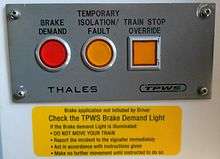
There is a TPWS panel located in each driving cab of a train or locomotive. The TPWS panel comprises two indicator lamps and a push switch. There is also a separate TPWS Temporary Isolation Switch which is not shown in the example photograph.
The push switch marked "Train Stop Override" is used to pass a signal at danger with authority - It ignores the TPWS TSS loops for around 20 seconds or until the loops have been passed, whichever is soonest.
The separate "Temporary Isolation Switch" will be activated by the driver when the train is being operated in degraded conditions such as Temporary Block Working where multiple signals will be need to be passed at danger with the signalman's authority. The driver must reinstate the system immediately at the point where normal working is resumed.
The AWS system and the TPWS system are inter-linked and if either of these has initiated a brake application, the "Brake Demand" indicator lamp will flash.
The "Temporary Isolation/Fault" indicator lamp will flash if there is a TPWS system fault, or will show a steady illumination if either the "Train Stop Override" or "Temporary Isolation Switch" has been activated.
TPWS use in depot personnel safety
An alternative to using derailers in Depot Personnel Protection Systems is to equip the system with TPWS. This equipment safeguards staff from unauthorised movements by using the TPWS equipment. Any unplanned movement will cause the train to automatically come to a stand when it has passed the relevant signal set at danger. This has the added benefit of preventing damage to the infrastructure and traction and rolling stock that a derailer system causes. The first known installation of such a system is at Ilford Depot. TPWS equipped depot protection systems are suitable only for locations where vehicles are driven in and out of the maintenance building from a leading driving cab - they are not suitable for use with loose coaching stock or wagon maintenance, where vehicle movements are undertaken by a propelling shunting loco (in this case the lead vehicles would not be equipped with the relevant TPWS safety equipment), nor will it prevent a run-away vehicle from entering a protected work area.
Variations
In some instances, due to low line speeds, an OSS may not be fitted. An OSS on its own may be used to protect a permanent speed restriction, a signal at danger, or buffer stop. Although loops are standard, buffer stops may be fitted with 'mini loops', due to the very low approach speed, usually 10 mph. When buffer stops were originally fitted with TPWS using standard loops there were many instances of false applications, causing delays whilst it reset, with trains potentially blocking the station throat, plus the risk of passengers standing to alight being thrown over by the sudden braking. This problem arose when a train passed over the arming loop so slowly that it was still detected by the train's receiver after the on-board timer had completed its cycle. The timer would reset and begin timing again, and the trigger loop then being detected within this second timing cycle would lead to a false intervention. As a temporary solution, drivers were instructed to pass the buffer stop OSSs at 5 mph, eliminating the problem, but meaning that trains no longer had the momentum to roll to the normal stopping point and requiring drivers to apply power beyond the OSS, just a short distance from the buffers, arguably making a buffer stop collision more likely than before TPWS was fitted. The redesigned 'mini loops', roughly a third the length of the standard ones, eliminate this problem, although due to the low speed and low margin, buffer stop OSSs are still a major cause of TPWS trips.
Recent applications in the UK have, in conjunction with advanced SPAD protection techniques, used TPWS with outer home signals that protect junctions with a higher than average risk by controlling the speed of an approaching train an extra signal section in rear of the junction. If this fails the resultant TPWS application of brakes will stop the train before the point of conflict is reached. This system is referred to as TPWS OS (Outer Signal).
Limitations
TPWS has no ability to regulate speed after a train passes a signal at danger in accordance with Stop and Proceed rules. However there are strict rules governing drivers' actions and train speed when passing signals at danger with authority and the use of TPWS on these occasions.
There are several reasons why a driver would be required to pass a signal at danger with authority, such as track circuit or axle counting failure. The driver will have been advised by the signaller to pass the signal at danger, proceeding with caution and being prepared to stop short of any obstruction and to obey all other signals. The signaller would expect the driver to know the requirement of pressing the "Trainstop Override" button on the TPWS panel to pass the signal without triggering a TPWS brake demand. A signaller is not allowed to inform the driver to operate any TPWS override, only that TPWS may be present at the signal that is required to be passed at Danger.
Due to the varying conditions under which a train may need to pass a signal at danger, it is seen as best to leave the appropriate speed to the driver's discretion, rather than have a fixed speed. The appropriate speed for a heavy freight train on a curved line during heavy rain will be much lower than for a fast braking passenger train on a straight line in clear and dry conditions.
Whilst critics claim TPWS is a cheap solution and putting lives at risk compared to fitting ATP, there have been very few fatalities in modern times (since the fitting of AWS) that would have been prevented had ATP been fitted but would still have occurred despite TPWS. The Southall rail crash would not have been prevented by TPWS yet could have been prevented by ATP (ironically fitted but not in use), yet would almost certainly have been prevented had the AWS been working. A combination of TPWS and AWS is most weak against accidents like that at Purley, where a driver repeatedly cancelled the AWS warning without applying the brakes, passing the danger signal at high speed. In this particular case though, the lower speed of the train and the very effective brakes of the EMU would have meant TPWS would likely have been effective anyway. Supporters of TPWS claim that even where it could not prevent accidents due to SPADs, it would likely reduce the impact and reduce or eliminate fatalities by at least slowing the train down but, in practice, it is likely that in these cases the driver would have already applied the emergency brakes well before the overspeed sensor.
Locations in use
The TPWS system is used in:
- The United Kingdom, with AWS magnets and with short overlaps
- Victoria, Australia, without AWS magnets and with full-length overlaps
An older variant of TPWS called the Auxiliary Warning System has been used by Mumbai Suburban Railway on the Western Line and Central Line since 1996.
References
- ↑ Network Rail: Step change in safety delivered on time and under budget - Monday 29 December 2003
- 1 2 3 4 "Appendix E - History of the Train Protection Warning System (TPWS)" (PDF). Signal passed at danger and subsequent near miss at Didcot North junction (22 August 2007). November 2008. Retrieved 2013-03-18.
- ↑ Professor John Uff QC FREng and The Rt Hon Lord Cullen PC (March 2001). "The Joint Inquiry into Train Protection Systems" (PDF). Retrieved 2013-03-18.