UK railway signalling

The railway signalling systems used across the majority of the United Kingdom rail network use line-side signals to advise the driver of the status of the section of track ahead.
The current signalling is based on a two, three, and four aspect colour light system using the absolute block principle; permissive block may only be used in certain limited circumstances. It is a basic progression of the original semaphore signalling that can still be found on many secondary lines. The use of lineside signals in Britain is restricted to railways with a maximum permissible speed of up to 125 mph (201 km/h).
Early days

In the days of the first British railways, "policemen" were employed by every railway company. Their jobs were many and varied, but one of their key roles was the giving of hand signals to inform engine drivers as to the state of the line ahead. They had no means of communication with their colleagues along the line, and trains were only protected by a time interval; after a train had passed him, a policeman would stop any following train if it arrived within (say) 5 minutes; for any between 5 and 10 minutes after, he would show a caution signal, and after 10 minutes, the line was assumed to be clear. Therefore, if a train failed midsection (as was very common in the early days), the policeman controlling entry to the section would not know, and could easily give a 'clear' signal to a following train when the section was not in fact clear. The number of collisions which resulted from this led to the gradual introduction of the absolute block principle; all systems of working other than this (including time-interval and permissive block) were outlawed on passenger lines in 1889, and all passenger lines were suitably equipped by 1895.
As train speeds increased, it became increasingly difficult for enginemen to see hand signals given by the policemen, so the railways provided various types of fixed signals to do the job, operated by the policemen, or signalmen as they soon became known (it is due to this that British railway slang still names signalmen as "Bobbies"). Many types were devised, but the most successful was the semaphore, introduced in 1841 and soon becoming widespread, although some other types did linger on until the 1890s.
Running signals
Semaphore signals
 Semaphore stop signal (lower quadrant type)
 Semaphore distant signal (lower quadrant type)
 Combined semaphore stop and distant signals (lower quadrant type)
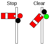
The traditional British signal is the semaphore, comprising a mechanical arm that rises or drops to indicate 'clear' (termed an "upper-quadrant" or "lower-quadrant" signal, respectively). Both types are fail safe in the event of breakage of the operating wire but lower-quadrant signals require a heavy counter-weight (usually in the form of the "spectacle" that carries the coloured lenses for use at night) to do that, while upper-quadrant signals return to "danger" under the weight of the arm.
During the 1870s, almost all the British railway companies standardised on the use of semaphore signals, which were then invariably of the lower quadrant type.[1] From the 1920s onwards, upper quadrant semaphores almost totally supplanted lower quadrant signals in Great Britain, except on former GWR lines.[2]
There are two main types of semaphore; stop and distant. The stop signal consists of a red, square-ended arm, with a vertical white stripe typically 9-12 inches (230–300 mm) from the end, and advises the driver whether the line immediately ahead is clear or not. A stop signal must not be passed in the "on" (danger) position, except where specially authorised by the signalman's instruction. By night, it shows a red light when "on" and a green light when "off" (clear).
The other type is the distant signal, which has a yellow arm with a 'V' ("fishtail") notch cut out of the end and a black chevron typically 9-12 inches (230–300 mm) from the end. Its purpose is to advise the driver of the state of the following stop signal(s); it may be passed in the "on" position, but the driver must slow his train to be able to stop at the next stop signal. When "off", a distant signal tells the driver that all the following stop signals of the signal box are also "off", and when "on" tells the driver that one or more of these signals is likely to be at danger. By night, it shows a yellow light when "on" and a green light when "off".
Current British practice mandates that semaphore signals, both upper and lower quadrant types, are inclined at an angle of 45° from horizontal to display an "off" indication.[3]
Colour light signals
 Green
Green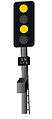 Double yellow
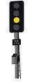 Yellow
 Red
Red
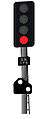
Colour-light signals exist in the UK in two-, three-, four- and five-aspect forms. The main aspects are:
- Flashing Green - Clear, the train may proceed normally. This aspect was only used on the 140 miles per hour (230 km/h) trial section of line between Peterborough and York.
- Green – Clear, the train may proceed normally. (On the 140 mph section of line above it means that the next signal shows two yellows.)
- Double yellow – Preliminary caution, the next signal is displaying a single yellow aspect.
- Single yellow – Caution, the driver must prepare to stop the train at the next signal.
- Flashing yellow - 'Caution or preliminary caution - single or double aspect' warning of a diverging route set at high speed turnouts, route is set and will give Green aspects after turnout.
- Red – Danger/Stop
The single yellow, double yellow and green aspects are known as 'proceed aspects' as they allow the train to pass the signal; the red aspect always requires the train to stop.
The most common type of four-aspect signal has four lenses arranged from top to bottom as follows:
- Yellow
- Green
- Yellow
- Red
Some use was made in the past of searchlight signals; these have one lamp, in front of which is placed either a red, yellow or green glass to show the respective aspect. For double-yellow a second lamp is fitted, illuminated only for the double-yellow aspect. The last of the traditional searchlight signals (i.e. with moving glasses inside) were removed in the 1990s, but the concept has resurfaced in the 2000s with the advent of LEDs which can show three different colours.
Four-aspect signalling is usually used either on busy or fast (or both) lines; in the case of the former, to allow shorter headways, and to give earlier warning of a "stop" aspect in the case of the latter. Where neither of these conditions apply, two- or three-aspect signalling is generally used instead.
Flashing yellow aspects

A flashing single or double yellow aspect indicates that a train is to take a diverging route ahead with a lower line speed than the main route, indicating to the driver to slow the train down in time for the speed limit of the diverging route. A flashing double yellow (only used in 4-aspect territory) means that the next signal is showing flashing single yellow. A flashing single yellow means that the next signal at the junction is showing (steady) single yellow with an indication for a diverging route, and the signal after (in advance of) the junction may be red. When the train has neared the junction and slowed down, the junction signal may 'step up' to the correct aspect depending on the state of the line ahead.
The two yellows in a flashing double-yellow flash in unison rather than alternately. This is done by switching over the 110BX power supply feeding the HR (yellow) and HHR (double-yellow) signal-lamp transformers to a special 110FBX supply switched at 1.2 Hz (or about 70 cycles per minute) when the junction points are set and locked for the divergence and the junction-signal itself is proved showing a proceed aspect for the divergence. The names 110BX and 110FBX indicate live 110 V AC supplies.
Failures
A failure of the changeover relay to switch on the flashing indication to the double-yellow aspect would not be a problem as it is considered a steady double-yellow followed by a flashing single-yellow aspect sequence is acceptable.
However, safety circuitry is connected to the single-yellow flashing supply to ensure that a failure of the single-yellow to change over to the flashing supply would abort the "approach release from yellow" sequence and re-impose the normal "approach control from red" sequence as failure of the single yellow to flash following a flashing double-yellow is considered potentially very dangerous.
Depending on the approach speed of trains, to a passenger it may seem that flashing aspects have failed when they have not. This is because the train passes the signal too quickly for a complete cycle to be observed from side-on.
Lens colour order
The red light of a multi-lamp signal is positioned so that it is nearest to the line of sight of the driver, meaning that it is at maximum brightness through its lens. For this reason, running signals on the ground have the red lamp at the top. Signal alignment is generally aimed towards a distance 200 metres in rear of the signal and at a height of 2.5 to 3 m from the left hand rail. Ground mounted signals are rarely so critical for alignment (hence ground mounting) and are often used in tunnels where the relative luminosity of the aspects are much higher.
The requirement of road signals that a stop light should be visible over a queue of traffic and as far back as possible (thus demanding an order with red above) does not apply to railways with a block signalling system as there is no traffic queuing within a block, there being only one train in a block at a time. With railway signals, red need not be at the top for maximum visibility over distance as the driver of a train will already be expecting a red signal, having passed a yellow one in the previous block. This advance warning is missing with road signals.
There are many variations on this basic theme, depending on the track layout (whether there are junctions, crossovers, stations, bay platforms, etc.) and at interfaces between areas with signalling systems with different numbers of aspects.
Unusual colour light aspects
- Flashing green – flashing green aspects are employed on the East Coast Main Line north of Peterborough. They were installed for 140 mph (225 km/h) running in connection with the testing of the new InterCity 225 electric trains, with a steady green limiting test trains to the normal speed limit of 125 mph (200 km/h). They no longer have official meaning, but remain in place and there are a couple of locations where the presence or absence of flashing provides useful information to drivers.
- Splitting distants – at some locations approaching a junction two heads are placed side by side. When this signal or the junction signal is at danger, one head is dark and the other shows red or single yellow. When the junction signal is not at danger, both heads show an aspect: the one for the route set ahead of the junction (left or right) shows the correct aspect while the other shows single yellow (or double yellow at an "outer splitting distant").
- Green over yellow, or green over green – the Liverpool Loop Line and London Underground use separate red/green "stop" and yellow/green "repeater" signals. If a repeater signal is at the same location as a stop signal, it is placed underneath it and lit only when the stop signal is green. Thus the order of the heads is (from top to bottom) green, red, green, yellow, and aspects are red, green over yellow, and green over green.
- Yellow over green – this was used in the experimental "speed signalling" at Mirfield to provide an additional caution. It meant that the next signal was showing double yellow. It was discontinued in 1970.
Approach release
At certain locations such as the final signal on approach to a terminus station or at a diverging route requiring a large speed reduction, approach release may be used. The driver will be "checked down" with a normal signalling sequence (green, double yellow, yellow for a four-aspect area) and the red signal clears when the train is close to it. Typically for low speed junctions (e.g. 25 mph (40 km/h) crossover on a 90 mph (140 km/h) line), the train will be brought down to nearly standing at the signal before it clears. The control of this can be achieved by a time-delay that commences on the approaching track circuit becoming occupied. After the elapsed time, the signal is allowed to "step-up" to the highest available aspect and display the junction indicator where applicable.
Where LED signalling is in use, an additional safety precaution ensures a failure of the signal proving does not cause an irregular or mutilated display to appear due to partial failures of elements.
This can be observed in practice – at Bescot Stadium northbound the new replacement signal, when cleared for the divergence for Walsall-bound trains, shows the junction-indicator with a red aspect for 2-3s before the main aspect clears – this is whilst the safety interlocking proves all the elements of the main aspects and junction-indicator lamps are intact.
With conventional filament-lamp multi-lens signals the red aspect only remains alight for a fraction of a second when the junction-indicator is proved, as filament lamps can be proved correctly alight much more quickly than LED units.
Subsidiary signals
Subsidiary signals are those which usually control only shunting moves, as opposed to train movements. Under this category come permissive signals and shunting signals.
Semaphore subsidiary signals
Permissive signals
Although British railway operation is based solely on the absolute block principle, there are certain situations in which permissive signals are used to govern certain movements. There are three types of permissive semaphore in Britain: calling-on, shunt-ahead, and warning signals. Today, all three look broadly the same; they are shaped like a normal stop signal, though only about two-thirds of the size, and are painted red with a white horizontal band running centrally along them. When "on", they show a small red or white light, and when "off", they display a small green light and an illuminated 'C', 'S' or 'W', depending on their function.
- Calling-on signal
The calling-on signal is by far the most common of the three types of subsidiary signal. It is mounted under the stop signal governing entry to (usually) a platform and, when pulled off, allows the driver to proceed cautiously for as far as the line is clear (or to the next stop signal). This can allow three basic moves to take place;
- A second train to run into and exchange passengers at an already partly occupied platform;
- Additional vehicles to be attached to the rear of a standing train;
- A locomotive to run into a platform occupied by coaches to be attached to them.
- Shunt-ahead signal
The shunt-ahead signal is normally mounted under the signal governing entry to the section ahead, and, as its name implies, allows a train to shunt forward into the section to clear a set of points without pulling off the main starting signal, which could give a driver the false impression that the section ahead is clear.
- Warning signal
The warning signal is the most unusual of the three types of British permissive signal. It is, like the shunt-ahead, placed under the signal governing entry to the section ahead, but its function is very different. For a signalman to accept a train, both his block section and the line for a quarter mile inside his outer home signal must usually be clear; the quarter mile is a precaution in case the driver fails to stop in time for the outer home signal. However, it is possible to accept a train under the "Warning Arrangement" if the block section, but not the quarter-mile overlap, is clear. As its name implies, the signalman must stop and caution the driver of the train concerned, and the warning signal simply replaces the signalman's caution where this operation is frequent. Because there is no margin for braking error, the warning arrangement cannot usually be applied to passenger trains: its commonest use is to allow a goods train to run into a section to shunt a siding in the middle of that section, while a train is still occupying the station ahead.
Shunting signals
 Sub signal
 Ground position light
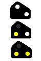 Yellow ground position light
Shunting signals allow a train to move forward onto a line which may already be occupied. They may be attached to a main signal in which case they are only cleared when the shunting movement is required (known as a subsidiary signal), and they display two white lights at an angle of 45°. The driver may pass the signal with caution at a speed which allows the train to stop short of any obstruction.
These signals may also be placed on the ground called a ground position light (GPL), or on a post with no corresponding main signal. In this case, the signals will show either two red lights or a red and white light in a horizontal arrangement, when no movement is signalled.
If two red lights or one red and one white are shown, the signal must not be passed.
When a shunting movement is signalled, the signal will show two white lights in a diagonal arrangement. This means the driver may pass the signal with caution at a speed which allows the train to stop at any obstruction. This type of signal is also used to designate a limit of shunt, the point up to which trains that are shunting are allowed to proceed. In this case, two red lights are displayed side by side, but no other aspect can be shown. No train is allowed to pass this fixed signal in the direction shown (this will be against the normal direction of travel on the track in question).
Two yellow lights or one yellow one white indicate a shunting movement is permitted past the signal but only for a move in a direction for which the signal cannot be cleared (for example, towards a headshunt rather than on to the main line). Again, two white lights at a 45° angle indicate shunting is permitted.
Red shunting signals
Red shunting signals are found in small-arm semaphore (the arms are about the same size as those of permissive signals) and disc varieties (the disc is about 12 inches/30 cm diameter). The small-arm semaphores are painted in the same way as a full-size stop signal, while the discs are painted white with a red horizontal band. A small-arm semaphore shows "clear" in the same way as a full-size stop signal, while a disc rotates through 45 degrees or so when pulled off so that the red band is angled. Both display small red or green lights by night. They authorise shunting moves to proceed for as far as the line is clear beyond them, i.e. the line is not definitely clear. They are usually used to govern movements out of yards, and the discs are also used for some movements on main lines; most common is to control movement over a trailing crossover.
Yellow shunting signals
Yellow shunting signals come in small-arm semaphore and disc varieties too, the small-arm semaphores being painted yellow with a black stripe and the discs either black or white with a yellow stripe; by night, they show small yellow lights when "on" and small green lights when "off". They are placed at yard exits where there is a headshunt, and perform virtually the same function as red shunting signals, with the exception that they can be passed when "on" if the points are set into the headshunt rather than out onto the main line. This is done to avoid having to clear the signal every time a move into the headshunt is made.
Modern subsidiary signals
Permissive signals
Modern-day permissive signals consist of two white lights at 45°, normally unlit. When lit, with the main aspect showing red, they instruct the driver to proceed but be prepared to stop short of any obstruction. When unlit, the driver obeys the main signal aspect. They can therefore function either as calling-on or shunt-ahead signals, depending on their location (the Warning Arrangement in colour-light areas, uses the main aspect in a similar fashion to approach release junction signalling, in this case it is called a Delayed Yellow ).
Shunting signals
Position-light shunting signals are used in colour-light areas instead of small-arm semaphore or disc shunting signals, and have the same meaning. They comprise three lenses in a triangular formation; two red lights or a red and a white light side by side is the signal's "on" aspect, while the "proceed" aspect is two white lights at an angle of 45°. A shunting signal that shows one yellow and one white light or two yellows horizontally when "on" is the colour-light equivalent of a yellow shunting signal and has exactly the same meaning.
Junction signals
 Left route
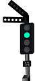 Second left route
 Route indicator
British railway signalling is unusual in that it employs the direction signalling philosophy, rather than that of speed signalling; in other words, a driver is informed of which route he will take at a junction, rather than the speed at which he should travel through it. This probably stems from the early days of railways when points and signals were not interlocked, and it was therefore important for a driver to know whether the points had been correctly set for him or not, and has stuck ever since.
Semaphore junction signals
In semaphore areas, junctions are signalled using a series of between 2 and 5 stop signal arms on one bracket or gantry, known as splitting signals. Each arm (usually) has its own post ("doll") on the bracket, and each arm applies to one possible route. The relative heights of the dolls usually convey some information about the lines to which they apply, although there is no definite standard. In some cases, the tallest doll applies to the highest-speed route; in others, it applies to what the railway considered the most important route. Traditionally, splitting distant signals would be provided – a series of side-by-side distant signals telling the driver which doll on the following stop signal was off; but practice since the 1920s has erred towards providing just one distant which is locked at caution if a large speed reduction is necessary. Drivers of trains must know which signal arm applies to which route, and the speed limit on that route; accidents have resulted from drivers either mis-reading splitting signals or forgetting speed restrictions, and consequently approaching junctions too fast.
Where there is a large number of possible routes, splitting signals are unsuitable because they would be easily confused, and route indicators are used instead. These consist of a black background, mounted under a single stop signal, on which is superimposed a white letter(s), number(s) or combination of the two, to make a code indicating the route to be taken. For example, if the possible routes were to Cambridge and to Norwich, a Norwich-bound train might be shown 'N' and a Cambridge-bound train 'C'. The route code is only shown when the signal is off. In semaphore areas, route indicators may be mechanical, with boards that slide into view to display the code; or electric "theatre-type", with a light projected through a suitably-printed screen.
Colour-light junction signals
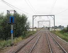
The colour-light equivalent of a splitting signal is the junction indicator, colloquially known as a "lunar indicator", "feather", or "horn" in Scotland. Mounted above a colour-light signal, they consist of a row of white lights (originally a single, long, u-shaped fluorescent tube in an open-fronted case), nowadays five but traditionally three, angled to the left or right depending on the direction of the divergance.[4][5] When the highest-speed route is set, the indicator is not illuminated (unless all routes are of a similar speed, in which case there is an indication for each route). When a diverging route is set, the respective junction indicator is illuminated. These can be used where there is a maximum of six routes as well as the 'straight' route, and where a maximum of three routes are to one side of the 'straight' route.
Where junction indicators are unsuitable, route indicators are also used in colour-light areas. They may take the form of a dot-matrix of white lamps, or, in more recent installations, fibre-optic displays driven from a single lamp to display the route code. At certain locations, no route indication is given for the highest-speed route. As with semaphore route indicators, they are usually restricted to areas where all routes are at low speed, often on the approach or departure from large stations.
In areas where speeds are lower and there are a number of routes which can be taken, alphanumeric (also called theatre-style) route indicators are used to display a number or a letter (e.g. a platform number or line designation) to denote the route the train is to take. They may be located above or beside the relevant signal. When a route is set and the signal is cleared, the relevant letter or number is shown. On shunting signals, where speeds are much lower, a miniature version of the alphanumeric route indicator is used.
When a route is set at a junction that involves the train taking a diverging route that must be passed at less than the mainline speed, a system known as approach release is used. There are a number of different types of approach release that are used on British railways but the most often used is approach release from red. This system has the signal before the diverging junction held at red until the train approaches it, whereupon it changes to a less restrictive aspect with the appropriate direction feather of five white lights. This is required so that the signals approaching show the correct caution aspects, slowing the train down for the junction. While the junction signal is held at red, the preceding signal will be displaying caution (yellow), and the one before that will display preliminary caution (double yellow) if it is a 4-aspect signal. This system allows for a gradual decrease in speed until a safe speed is reached for the train to move through the junction.
Another common system is approach release from yellow with flashing aspects in rear. It is essentially similar to approach release from red, except that the junction signal is released from yellow and the signals in rear will flash to warn the driver that the train will be taking a diverging route ahead. Where the turnout speed is the same as the mainline speed, approach release is not necessary.
Speed restriction signs
Speed restrictions are imposed on a route to ensure a train is always travelling at a safe speed for the prevailing conditions along the track.
Permanent speed restrictions
Permanent speed restrictions are imposed where the route encounters a hazard such as a tight radius curve, level crossings, certain junctions, tunnels and bridges and where the train is entering a terminal station.

- Warning boards
Warning of a permanent speed restriction (PSR) ahead of 75 mph (121 km/h). Typically placed about a half mile to a mile before the start of the permanent speed restriction, depending upon the difference between the maximum permitted line speed and the restricted line speed. Colloquially known as 'Morpeth boards', after the 1969 derailment at Morpeth, Northumberland that led to their introduction.

Warning of a permanent speed restriction on the left diverging route of 75 mph (121 km/h). Again, typically placed about a half mile to a mile before the permanent speed restriction on the diverging route, depending upon the difference between the maximum permitted line speed and the restricted line speed.

- Permanent speed restriction signs
Start of permanent speed restriction of 125 mph (201 km/h) on the main route

Start of differential permanent speed restriction, with two varying restrictions for different types of trains. The figure above the line is the maximum permitted speed for freight trains, while the figure under the line is the maximum line-speed for passenger trains. In this example, freight is permitted to 35 mph (56 km/h), while passenger trains are permitted to 70 mph (110 km/h).

Start of permanent speed restriction of 40 mph (64 km/h) on the diverging route to the left. Placed before the diverging route to instruct or remind the driver of the maximum line speed on the diverging route.
Temporary speed restrictions
Due to engineering works, a temporary speed reduction (TSR) may be enforced at a particular location.

Warning of temporary speed restriction of 40 mph (64 km/h) ahead.

The start and termination indicators of a temporary speed restriction of 40 mph (64 km/h). The speed restriction continues to apply until the last vehicle of the train has passed the 'T' indicator.
A temporary speed restriction warning board showing R is positioned beyond the end of platforms where trains may stop between the warning board and the start of the restriction, to remind drivers of the restriction ahead. A warning or commencement board showing a diagonal line means that a TSR shown in the operating notices is not in place and trains may proceed at normal line speed.
Other signals
Preliminary Routing Indicators (PRIs) are installed on the approach to certain junctions. When the junction signal is displaying a 'proceed' aspect, the PRI will display an arrow. The arrow points up when the highest speed route is set. When a diverging route is set, the arrow points in the appropriate direction (mimicking the junction indicator on the junction signal). This advance indication gives the driver an opportunity to stop before the junction points, if wrongly routed. At the present time, PRIs are few in number, but they are likely to become more common.[6]
Proceed on Sight Authority is a new concept which introduces an additional aspect to allow the signalman to authorise drivers to pass signals when they are at red due to influences within the interlocking. The signal will notionally be used where the route setting and locking function is still proved to be operable but a function such as train detection or lamp proving of a signal ahead may be failed. The authority will allow the driver to pass the signal and proceed at a speed slow enough that they may stop short of any obstruction (in common with other degraded modes of operation) The term may be abbreviated to "PoSA".[7]

Off Indicator: An illuminated off indication means the associated signal is showing a proceed aspect. These are mainly used at stations, for the benefit of the train-crew and platform staff. When the display is blank, it means that the associated signal is at danger. An illuminated indication CD (close doors) is an instruction to close the train's power-operated doors. An illuminated indication RA or R (right away) means that station duties are complete and the train may depart.
A SPAD indicator[8] is a separate indicator which may be positioned after a main signal where there is a likelihood of a serious collision at a junction if a SPAD (signal passed at danger) occurs at the main signal. SPAD indicators are mounted against a blue backplate or surround. They are normally unlit but following a SPAD they display a steady red light between two flashing red lights arranged vertically. Any driver who sees a SPAD indicator illuminated must stop their train immediately, even if they can see that the signal pertaining to their line is showing a proceed aspect.
Banner repeater signals
 Banner on
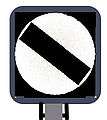 Banner off
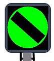 Banner green
Banner repeater signals repeat the indication of the following signal, where the driver's view of it may be restricted, for example because of track curvature or a bridge abutment.
- Banner on: The signal being repeated is showing a Stop aspect, and the train must be prepared to stop at that signal.
- Banner off: The signal being repeated is showing a proceed aspect, so can be passed. If the AWS sounds a horn as this signal is passed, it indicates that the next signal is showing either a caution or preliminary caution aspect.
- Green banner: Although not in widespread use, some banner repeaters can display a third (green) indication, meaning that the signal being repeated is showing a Clear aspect.
Obsolete signals
Purple lights
Purple lights were used on some early signals in particular circumstances (e.g. wrong-road or goods lines).[9]
Three-position semaphore signals
From 1914, a small number of British installations used motor-operated three-position semaphore signals of North American origin. These worked in the upper quadrant to distinguish them from the two-position lower quadrant semaphores that were standard at the time of their introduction. When the arm was inclined upwards at 45°, the meaning was "caution" and the arm in the vertical position meant "clear". Thus, three indications could be conveyed with just one arm and without the need for a distant arm on the same post.
Euston to Watford experimental system
This scheme, on the face of it, was a fairly standard colour light system, with each stop signal (which could show red or green) having an attendant repeater signal (showing red, yellow or green – the red used only for when the two stop signals on either side were also red). What made the scheme unusual was the provision of an automatic 'calling on' facility. The stop signals had an additional signal head ('marker light') that featured a red aspect plus a miniature yellow aspect. This marker light was mounted part way up the post. On repeater signals, the marker light was offset to the left-hand side of the post to indicate that the 'stop and proceed' rule applied. Junction stop signals were provided with two main signal heads, one mounted higher than the other. Splitting distant signals had three main heads, the centre one mounted higher than the other two.
When a train stopped at a red stop signal, its presence on the track started a time delay relay. At the conclusion of the time delay, the red marker light was extinguished and replaced by the miniature yellow (the upper red aspect remained lit). The train stop also lowered. The calling on aspect authorised the driver to proceed, but to be prepared to stop short of another train.
The scheme was not considered a great success. In fact, during periods of severe service disruption, it was not unusual to see several trains buffer-to-buffer along the line, though this occurred when the line was much busier than now. Concern was expressed that similar coloured aspects had different interpretations depending on where on the signal they appeared.
The system was finally identified for replacement following an accident at Kensal Green, when a main line train ran into the back of Bakerloo Line train.[10] The driver had apparently mistaken the calling on aspect for a normal yellow aspect (the signal was temporarily operating on a maximum yellow due to track side work). The indications were that the driver was distracted as his pay slip and its envelope were recovered from the wreckage – but this was never proved as the cause. It was also suggested that the driver may not even have checked the indications having observed the fall of the train stop. The entire line was resignalled to the standard colour light system in 1988.
Warning systems
Because of the propensity for heavy fog in some parts of the British Isles, fog signal rules were established on the UK railway system to keep train traffic moving without incurring the severe delays that would be necessary if drivers had to stop or travel slowly up to each signal and read its indication. During heavy fog, fogsignalmen would be stationed at distant signals with a lantern and detonators – small explosive charges that could be strapped to the rail to be exploded by the wheels of a train. The fogsignalman's duty was to repeat the indication of the signal using his lantern; the semaphore arm was usually obscured by fog and hence invisible to the driver of a moving train. If the distant signal were displaying 'caution' (warning that a signal ahead was at 'danger'), the detonators remained on the rail and the fogsignalman would show a yellow lamp to show 'caution'; if the distant signal were clear, the detonators would be removed from the rails and a green lamp would be displayed.
Britain's Great Western Railway introduced the Automatic Train Control (ATC) system in 1906. This system is the forerunner of today's Automatic Warning System (AWS) and consists of an electrical system that sounded a bell in the cab as the train approached a signal at clear. Power was fed through a metal ramp to a pickup on the underside of the locomotive to power the bell. An absence of the electrical voltage on the ramp caused a warning horn to sound in the locomotive's cab. The driver then had a set time to acknowledge the warning and start braking his train accordingly. If the driver did not acknowledge the warning, the brakes would be applied automatically. Where this was implemented, it did away with the need for fog signalling, since the driver could tell the state of the distant signal regardless of his ability to see it.
The current system of AWS in use on Britain's railways is similar in principle to the Great Western's ATC but does not rely on physical contact between the track equipment and the train; instead an inductive system is used.
On passenger lines, AWS is now often supplemented by the Train Protection & Warning System (TPWS). TPWS will automatically apply the train's brakes in the event of a fitted signal being passed at danger without authority.
See also
Notes and references
- ↑ Vanns, M.A., (1997), An Illustrated History of Signalling, Ian Allan, ISBN 0-7110-2551-7, p.25
- ↑ Vanns, M.A., (1995), Signalling in the Age of Steam, Ian Allan, ISBN 0-7110-2350-6, p.80
- ↑ Online Rulebook: Module S1 / Section 3.4 – Semaphore Signals Archived August 13, 2011, at the Wayback Machine.
- ↑ Green, Jonathon (1987). Dictionary of jargon. London: Routledge & Kegan Paul. p. 212. ISBN 0-7100-9919-3.
- ↑ Vanns, Michael (1997). An illustrated History of signalling. Shepperton, England: Ian Allen. p. 58. ISBN 0-7110-2551-7.
- ↑ Rule Book Amendments module, Issue 16 (March 2013), page 18 Archived August 19, 2014, at the Wayback Machine.
- ↑ Railway Group Standard GE/RT8071
- ↑ Online Rulebook: Module S1 / Section 4.5 – SPAD Indicator
- ↑ S&DJR wrong-road signals
- ↑ Sawyer, D A (22 November 1988). "Report on the Collision that occurred on 16th October 1986 at Kensal Green in the London Midland Region British Railways". The Railways Archive. Department of Transport. Retrieved 9 October 2015.
External links
- Railway Group Standard: GK/RT0045 Lineside Signals, Indicators and Layout of Signals
- Information on traditional British signalling
- Docklands Light Railway signalling system
- History of Railway Signalling in the Derby area
- Railway Signs and Signals of Great Britain
- Clive Feather's Junction Signalling
- SimSig UK Network Rail Signalling simulations