Matched Z-transform method
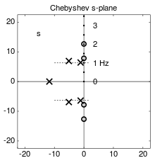
The s-plane poles and zeros of a 5th-order Chebyshev type II lowpass filter to be approximated as a discrete-time filter

The z-plane poles and zeros of the discrete-time Chebyshev filter, as mapped into the z-plane using the matched Z-transform method with T = 1/10 second. The labeled frequency points and band-edge dotted lines have also been mapped through the function z=eiωT, to show how frequencies along the iω axis in the s-plane map onto the unit circle in the z-plane.
The matched Z-transform method, also called the pole–zero mapping[1][2] or pole–zero matching method,[3] is a technique for converting a continuous-time filter design to a discrete-time filter (digital filter) design.
The method works by mapping all poles and zeros of the s-plane design to z-plane locations z=esT, for a sample interval T.[4]
Alternative methods include the bilinear transform and impulse invariance methods.

Responses of the filter (dashed), and its discrete-time approximation (solid), for nominal cutoff frequency of 1 Hz, sample rate 1/T = 10 Hz. The discrete-time filter does not reproduce the Chebyshev equiripple property in the stopband due to the interference from cyclic copies of the response.
References
- ↑ Won Young Yang (2009). Signals and Systems with MATLAB. Springer. p. 292. ISBN 978-3-540-92953-6.
- ↑ Bong Wie (1998). Space vehicle dynamics and control. AIAA. p. 151. ISBN 978-1-56347-261-9.
- ↑ Arthur G. O. Mutambara (1999). Design and analysis of control systems. CRC Press. p. 652. ISBN 978-0-8493-1898-6.
- ↑ S. V. Narasimhan and S. Veena (2005). Signal processing: principles and implementation. Alpha Science Int'l Ltd. p. 260. ISBN 978-1-84265-199-5.
This article is issued from Wikipedia - version of the 10/16/2016. The text is available under the Creative Commons Attribution/Share Alike but additional terms may apply for the media files.