Unbalanced circuit

In electrical engineering, an unbalanced circuit is one in which the transmission properties between the ports of the circuit are different for the two poles of each port. It is usually taken to mean that one pole of each port is bonded to a common potential (single-ended signalling) but more complex topologies are possible. This common point is commonly called ground or earth but it may well not actually be connected to electrical ground at all.
Examples
Passive filter
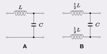
The figure shows two versions of a simple low-pass filter, unbalanced version (A) and balanced version (B). Both circuits have exactly the same effect as filters, they have the same transfer function. However, on the unbalanced circuit, the bottom pole of the input port is connected directly to the bottom pole of the output port. Thus, the impedance between the top poles is greater than the impedance between the bottom poles from input to output. For a circuit to be balanced the impedance of the top leg must be the same as the impedance of the bottom leg so that the transmission paths are identical. To achieve this, the inductor in the balanced version is split into two equal inductors, each with half the original inductance.
Tuned amplifier
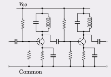
The figure shows the circuit of a typical tuned amplifier. The lower pole of the input port is connected directly to the lower pole of the output port. This connection also forms the negative rail of the supply voltage. This scheme is typical of many electronic circuits that are not required to have differential inputs or outputs. An example of a circuit that does not follow this pattern is the differential amplifier.
Advantages and disadvantages
The basic advantage of using an unbalanced circuit topology, as compared to an equivalent balanced circuit, is that far fewer components are required. The difficulties come when a port of the circuit is to be connected to a transmission line or to an external device that requires differential input or output. Many transmission lines are intrinsically an unbalanced format such as the widely used coaxial cable. In such cases the circuit can be directly connected to the line. However, connecting an unbalanced circuit to, for instance, a twisted pair line, which is an intrinsically balanced format, makes the line susceptible to common-mode interference.
For this reason, balanced lines are normally driven from balanced circuits. One option is to redesign the circuit so that it is in a balanced format. If that is not possible or desirable, a balun, a device for converting between balanced and unbalanced formats, may be used.
References
- Don Davis, Eugene Patronis, Sound System Engineering, p. 433, CRC Press, 2014 ISBN 1136119345.
- Douglas Self, Audio Power Amplifier Design, pp. 649-654, Taylor & Francis, 2013 ISBN 1136123822.
- R.S. Sedha, A Textbook of Electronic Circuits, p. 627, S. Chand, 2008 ISBN 8121928036.