Monotype System
The Monotype system is system for printing by hot-metal typesetting from a keyboard. The two most significant differences from the competing Linotype machine are:
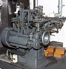
- It is divided into two machines, the Monotype keyboard and the Monotype caster, which communicate by perforated paper tape. It is not necessary to have the same number of each machine.
- The Monotype caster casts individual letters, which are assembled into lines in a fashion similar to classical movable type. This requires a more complex high-speed water-cooled casting mold, but only requires one matrix per possible character.
A Monotype operator enters text on a Monotype keyboard, on which characters are arranged in the QWERTY arrangement of a conventional typewriter, but with this arrangement repeated multiple times. Thus, the typesetter moves his hands from one group of keys to another to type uppercase or lowercase, small capitals, italic uppercase or italic lowercase, and so on.
When the text nears the right margin, a drum on the keyboard indicates codes which are punched on the paper tape with special keys to indicate how the line is to be justified. The tape is then taken to a Monotype caster, which reads the tape and produces a column of justified type from which the text entered on the keyboard can be printed.
History
In 1885, the American inventor Tolbert Lanston applied for a patent on a typesetting system that included the basic Monotype keyboard, but which produced a printing surface through a cold-stamping method. In 1890, he filed a subsequent patent, which covered the Monotype caster.
In 1897, the Lanston Monotype Corporation opened a branch in England, which later became an independent company.
Design
Keyboard
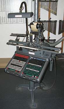
A Monotype keyboard allows a keyboard operator to prepare a perforated paper tape, called ribbon, that will direct the casting of type separately from its actual casting. The keyboard on which the operator types is removable, as is a set of keybars under the keys; the keybars, corresponding to each key, determine which holes will be punched in the tape. During operation, two sets of keys and keybars are placed in two side-by-side trays on the keyboard. The keybars are adjustable, so that the coding of the keys can be changed. Keytops also are replaceable, so that the keyboard can be reconfigured.
Matrix-Case
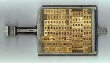
For the Monotype caster to produce types with the shape of the desired character on their face, a matrix with that character incised in it must be moved to the top of the mold in which the type slug will be cast. This is achieved by placing a rectangular array of brass matrices, each of which is one-fifth inch square, in a holder, called the matrix-case. Originally, it contained 225 matrices, in 15 rows and 15 columns; later versions of the Monotype caster expanded that first to 15 rows and 17 columns (255 matrices), and then to 16 rows and 17 columns (272 matrices).
The paper tape that controls casting contains 14 columns of holes that indicate the row of the matrix-case to be used, and 14 columns of holes that indicate the column of the matrix-case to be used. Originally, one row and one column of the matrix-case were indicated by the absence of a hole, and each of the others was indicated by a single hole. When the matrix-case was enlarged, some columns or rows of the matrix-case were indicated by combinations of two holes instead.
The row of the matrix-case on which the matrix for a character is contained also indicated the width of that character. This was one major reason why reconfiguring the keyboard needed to be easy, since the arrangement of characters in the matrix case would varied with the typeface. A part called the wedge indicated the width corresponding to each row of the matrix-case.
Justification
The width of a type slug cast on the Monotype varied from 3 to 18 units. (A special attachment was required to reduce the minimum from 4 units to 3 units.) A width of 18 units corresponded to the set width of the typeface. Thus, if a typeface was described as “12 set”, 18 units would correspond to one pica em. (A pica em is a horizontal distance equal to 12 points.)
The 12-point size of a typeface could also be 12 set, the 11-point size could be 11 set, and so on. But this was not always true: some typefaces could be somewhat wider or narrower than the standard, and many typefaces were modified to be slightly wider in smaller sizes. The set size could be varied in units of ¼ point.
Thus, while the Monotype unit system was normally described as one of 18 units to the em, it was 18 units to the em of the set size, not necessarily the em of the actual type size in use.
When text was typed on the Monotype keyboard, the keyboard kept track of the number of units taken up by the characters in the line, and also the number of “justifying spaces” in the line. When the right margin was approached, this information was indicated to the operator on a rotating drum on the keyboard. As part of finishing a line of text, this information was punched on the tape using two rows of special keys on the keyboard.
In order that the Monotype caster would know ahead of time how wide to make the spaces in a given line of text, the tape was placed on the caster so as to be read in the reverse order from that in which the text was typed.
Justification wedges
Justification was obtained with a system of wedges. The caster has an accuracy of 2000 parts of an inch (in modern terms, 2000 dpi).
- the wedge belonging to the layout of the diecase or matrix-case
- This wedge made a similar movement as the diecase, and the rows are polished according to the layout and the set of the used font.
- 0005-justification wedge
- This wedge can be laid in 15 different positions; the difference between two positions is .0005 inch.
- 0075-justification wedge
- This wedge can be laid in 15 different positions; the difference between two positions is .0075 inch.
- unit-adding wedge
- Using this wedge added 1, 2, or 3 units to the cast character. The attachment used for this needed some extra coding.
- the upper transfer-wedge
- This wedge was used when the justification were in use.
- the lower transfer-wedge
The combined actions of all these wedges governed the opening of the mould-blade, and in this way the width of the character or space to be cast was adjusted.
The position of the 0005- and 0075-wedges was put onto the right position during the codes that marked the start of casting the line. Two codes were used during a procedure that was called:
Double justification
- The first code, with three holes in the ribbon, caused the following actions:
- the pump was stopped
- both justification-wedges moved to the position of 0005
- the previous line already cast was transferred to the galley
- the second code, with two holes in the ribbon, was needed:
- to halt the pump for this machine-cycle
- to activate the pump-mechanism for the next machine cycle
- to bring the 0075-wedge in the desired position
The 3/8-position was called “neutral”. In this position, the 0075-wedge was at row 3, and the 0005-wedge was at row 8. In this position no width was added to the space or character to be cast. The minimum was 1/1. In this position the width of the cast was 2 × .0075″ + 7 × .0005″ = 0.0185″ less. The maximum 15/15 added a lot more to the cast: 12 × .0075″ + 7 × .0005″ = .00935″. The operator had to be aware that the opening of the mould should always be smaller than .2″ because otherwise the matrix could not seal the mould, and a splash of molten lead would occur.
Single justification was used to change the position of the justification wedges whenever needed, without transferring the line to the galley. This procedure was also used to adjust the spaces in more than one segment within a line. In this way it was possible to cast complete time-tables.
- The first code, with two holes in the ribbon, caused the following actions:
- the pump was stopped and halted
- the 0005-justification-wedge moved to its desired position
- the second code, with two holes in the ribbon, was needed:
- to ensure no pump-action during this machine-cycle
- to activate the pump-mechanism for the next machine cycle
- to bring the 0075-wedge in the desired position.
Besides this, there was also the possibility to cast high-spaces. Those high-spaces could support any overhanging character. When a character could not be cast at the desired width where it was put into the matrix-case, the character could be cast. A part of the sign would not be supported by the ingot. Directly after the character was cast, one or more high-spaces of 5 or 6 units were cast, to add to the desired width and to support the sign, in order to resist the pressure during the printing-process.
On top of this, there was the possibility of unit-shift. With this attachment it became possible to use a matrix-case with an extra row: 16 × 17 positions. The wedge still had exactly 15 positions. The matrix-case was, when needed, forced to go to the next row. The matrix was cast at the width of the wedge 1 position higher. This system made it possible to place more matrices in the matrix-case. Another advantage for Monotype was that it made it possible to change the layout of the matrix-case in such a way that any customer could get its own personalized layout.
There was a second 16×17 system, in which both the matrix-case and the wedge had 16 possible positions. This system was rather expensive, because of all the extra wedges needed that could not be used on other machines. The 16th row was coded with a code of two or three letters. Of this system there have been two variants: the extra row was coded with either MNH or MNK.[1]
See also
References
- ↑ The Monotype Keyboard operator's manual, 1950, The National Committee of Monotype user's Association, London, UK
- Printing Industries of America (1953). A Composition Manual. Brooklyn, NY.
- Lanston Monotype Machine Co. (1912). The Monotype System. Philadelphia.
- Lucien Alphonse Legros, John Cameron Grant (1916). Typographical Printing-Surfaces.
| Ways to make impressions |
|  | |||||||||
|---|---|---|---|---|---|---|---|---|---|---|---|
| Typesetting |
| ||||||||||
| Printing press |
| ||||||||||
| Other equipment | |||||||||||