Linotype machine


The linotype machine (/ˈlaɪnətaɪp/ LYN-ə-typ) is a "line casting" machine used in printing sold by the Mergenthaler Linotype Company and related companies. It was a hot metal typesetting system that cast blocks of metal type for individual uses. Linotype became one of the mainstay methods to set type, especially small-size body text, for newspapers, magazines and posters from the late 19th century to the 1970s and 1980s, when it was largely replaced by phototypesetting, offset lithography printing and computer typesetting. The name of the machine comes from the fact that it produces an entire line of metal type at once, hence a line-o'-type, a significant improvement over the previous industry standard, i.e., manual, letter-by-letter typesetting using a composing stick and drawers of letters.
The linotype machine operator enters text on a 90-character keyboard. The machine assembles matrices, which are molds for the letter forms, in a line. The assembled line is then cast as a single piece, called a slug, of type metal in a process known as hot metal typesetting. The matrices are then returned to the type magazine from which they came, to be reused later. This allows much faster typesetting and composition than original hand composition in which operators place down one pre-cast metal letter, punctuation mark or space at a time.
The machine revolutionized typesetting and with it especially newspaper publishing, making it possible for a relatively small number of operators to set type for many pages on a daily basis. Before Ottmar Mergenthaler's invention of the linotype in 1884, daily newspapers were limited to eight pages.[1]
History
Overview
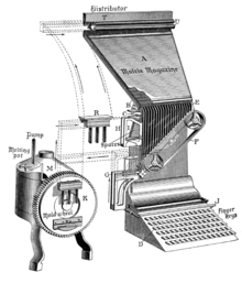
The linotype machine consists of four major sections:[2]
- Magazine
- Keyboard
- Casting mechanism
- Distribution mechanism
The operator interacts with the machine via the keyboard, composing lines of text. The other sections are automatic; they start as soon as a line is completely composed.
Some linotype machines included a paper tape reader. This allowed the text to be typeset to be supplied over a telegraph line (TeleTypeSetter). It also allowed for several tape perforator operators to prepare paper tape to be processed by a single linotype machine, essentially decoupling the typing speed of the operators from the operating speed of the linotype machine.
Design
Matrices
Each matrix contains the letter form for a single character of a font of type; i.e., a particular type design in a particular size. The letter form is engraved into one side of the matrix. For sizes up to 14 points, and in some matrices of size 16 to 24 points, the matrix has two letter forms on it, the normal and auxiliary positions. The normal position has the upright (Roman) form of a given character, and on the auxiliary, the slanted (Italic) form of that character will be used, but this can also be the boldface form or even a different font entirely. The machine operator can select which of the two will be cast by operating the auxiliary rail of the assembler, or, when setting entire lines of italics, by using the flap, which is a piece that can be turned under a portion of the first elevator column. This is the origin of the old typesetting terms upper rail for italic and lower rail for Roman characters. These terms have persisted in phototypesetting technology even though the mechanics of the auxiliary rail do not exist there. The character on a Linotype matrix, when viewed, is not inverted as a letter for conventional movable type would be, and the letter is incised below the surface rather than raised above it. This is because the matrix is not used directly to print onto the paper—rather, it is used as part of a mold from which a metal slug will be cast. The slug has its features reversed: therefore, the matrix does not.
Magazine section
The magazine section is the part of the machine where the matrices are held when not in use, and released as the operator touches keys on the keyboard. The magazine is a flat box with vertical separators that form "channels", one channel for each character in the font. Most main magazines have 90 channels,[3] but those for larger fonts carried only 72 or even 55 channels. The auxiliary magazines used on some machines typically contained 34 channels or, for a magazine carrying larger fonts, 28 channels.
The magazine holds a particular font of type; i.e., a particular type design in a particular size. If a different size or style was needed, the operator would switch to a different magazine. Many models of the Linotype machine could keep several magazines (as many as four) available at a time. In some of these, the operator could shift to a different magazine by raising or lowering the stack of magazines with a crank.[4] Such machines would not allow mixing fonts within a single line. Others, such as the Model 9, allowed arbitrary mixing of text from up to four magazines within a single line.
Escapement
In a linotype machine, the term escapements refers to the mechanisms at the bottom of the magazine that releases matrices one at a time as keys are pressed on the keyboard. There is an escapement for each channel in the magazine.
Maintenance and lubrication
To keep the matrices circulating smoothly throughout the machine, it is necessary that oil not be allowed anywhere near the matrix path. If oil is found in the matrix's path (due to careless maintenance or over-lubrication of nearby parts), it combines with dust, forming a gummy substance that is eventually deposited in the magazine by the matrices. The most common result is that the matrix will not be released from the magazine at its usual speed, and almost always results in a letter or two arriving out of sequence in the assembler — a "matrix transposition". When these machines were in heavy use, it was not uncommon for an operator to set type at the rate of over 4,000 ems per hour (the fastest operators being able to exceed 10,000 ems per hour) so careful lubrication and regular cleaning were essential to keep these machines operating at their full potential.
Keyboard and composing section
In the composing section, the operator enters the text for a line on the keyboard. Each keystroke releases a matrix from the magazine mounted above the keyboard. The matrix travels through channels to the assembler where the matrices are lined up side by side in the order they were released.
When a space is needed, the operator touches the spaceband lever just to the left of the keyboard. This releases a spaceband from the spaceband box. Spacebands are stored separately from the matrices because they are too big to fit in the magazine.
Once enough text has been entered for the line, the operator depresses the casting lever mounted on the front right corner of the keyboard. This lifts the completed line in the assembler up between two fingers in the "delivery channel", simultaneously tripping the catch holding it in position. The spring-operated delivery channel then transports the line into the casting section of the machine, and engages the clutch that drives the casting section and the subsequent transfer into the distribution section. The operator is now finished with the line; the remaining processing is automatic. While the line is being cast, the operator can continue entering text for the next line.
Keyboard
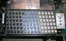
The keyboard has 90 keys. There is no shift key; uppercase letters have keys separate from the lowercase letters. The arrangement of letters corresponds roughly to letter frequency, with the most frequently used letters on the left.
The first two columns of keys are: e, t, a, o, i, n; and s, h, r, d, l, u. A Linotype operator would often deal with a typing error by running the fingers down these two rows, thus filling out the line with the nonsense words etaoin shrdlu. This is known as a "run down". It is often quicker to cast a bad slug than to hand-correct the line within the assembler. The slug with the run down is removed once it has been cast, or by the proofreader.
The linotype keyboard has the same alphabet arrangement given twice, once for lower-case letters, the keys in black, on the left side of the keyboard, and once for upper-case letters, the keys in white, located on the right side of the keyboard. The blue keys in the middle are punctuation, digits, small capital letters and fixed-width spaces. In proper keyboard operation, an experienced operator's left hand operates only the spaceband key and the left column of keys. The operator's right hand strokes the remaining keys on the entire keyboard.
The keys of the keyboard are connected by vertical pushrods to the escapements.[5] When a key is pressed, the corresponding escapement is actuated, which releases a matrix from the magazine. With one exception, each key corresponds directly to a channel in the standard (90 channel) magazine. The one exception is the lower-case letter e: that letter is used so often that the 90 channel magazine actually has 91 channels, with two channels (the leftmost two) both used for the letter e. Similarly, the 72 channel magazine actually has 73 channels, with the leftmost two being used for lower-case e. Alternate lines release matrices alternately from the two e channels in the magazine.[6]
On machines that support multiple magazines, there is a shifting mechanism that controls which magazine is currently connected to the keyboard. In most machines, this is done by raising or lowering the stack of magazines.[7]
Spaceband box
In justified text, the spaces are not fixed width; they expand to make all lines equal in width. In linotype machines this is done by spacebands. A spaceband consists of two wedges, one similar in size and shape to a type matrix, one with a long tail. The wide part of the wedge is at the bottom of the tail, so pushing the tail up expands the spaceband.
Due to their size, spacebands are not held in the magazine, but in a spaceband box[8] and released one at a time by pressing the spaceband lever at the left edge of the keyboard.
Assembler
Matrices released from the magazine, and spacebands released from the spaceband box, drop down into the assembler. This is a rail that holds the matrices and spacebands, with a jaw on the left end set to the desired line width. When the operator judges that the line is close enough to full, he raises the casting lever on the bottom of the keyboard to send the line to the casting section of the linotype machine. The remaining processing for that line is automatic; as soon as the finished line has been transferred to the casting section, the operator can begin composing the next line of text.
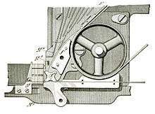
Casting section
The casting section of the machine operates intermittently which is triggered by the operator at the completion of the line. The full casting cycle time is less than 9 seconds. Motive power for this was from a clutch operated drive running large cams (the keyboard and distributor sections ran all the time, since distribution may take much longer, however the front part of the distributor completed its job prior to the next line of matrices to be distributed). The construction of the machine was such that both the return of the former line to the magazine and the composition of the next line could occur while the current line was being cast. Productivity with the machine was high as these three functions occurred simultaneously.
Older machines typically had a 1/3 hp 850 or 1140 revolution per minute motor geared to the main clutch wheel, the inner shaft engaging this wheel while the casting cycle was in operation. An external leather belt on this wheel ran a second jack-shaft, which powered the distributor and keyboard matrix conveyor and escapements through additional belting off this shaft. Gas fired pots, such as in the illustration below, were most common in the earlier years, with the pot being thermostatically controlled (high flame when under temperature and low flame when up to temperature), and then a second smaller burner for the mouth and throat heating, or else, with the more modern installations running on 1500 watt electric pots with an initially rheostat controlled mouth and throat heaters (several hundred watts on the electric models)(to keep the lead and tin type metal liquified just prior to being cast) to precisely adjust temperature. Motors were offered for any standard power used by the worldwide customer, namely direct current either 110 or 220 volts, or alternating current 25, 40, 50, or 60 Hz, and 110 or 220 volts, single, two or three phase. (All electric heaters were arranged for single phase no matter what the supply was, however condensers were installed on pilot contacts to quench sparking if run from DC mains, the heaters running equally well on either dc or ac as long as the voltage was correct). Newer machines, and the larger machines above 36 EM Matrix size typically used the more standardized 1/2 horsepower motor after v-belts came into common use in the 1930s. The large machines also had the so-called 'double pot', with either larger gas burners, or else 2250 watt pot heaters and larger mouth and throat heaters. The most modern Linotypes had the mouth and throat heaters thermostatically controlled, an improvement over the manual rheostat adjustment, or gas flame adjustment.
Prior to the 1930s, a very compact 'pancake' motor was mounted with a drive gear just above the main clutch wheel. The recommended motor was a polyphase model, since it was the physically smallest and had only one moving part (the shaft). But, if the polyphase motor was not selected and it was desired to use a single phase motor on polyphase service, then multiple machines had their motor and heater loads 'balanced' so that any 2 or 3 machines would appear to the electric utility as a balanced polyphase load; in any event the Linotype company would supply whatever drive was necessary, even using kerosene heaters and line-shaft operated machines, in locales without electricity.
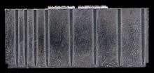
The casting section receives completed lines from the assembler, and uses these to cast the type slugs that are the product of the linotype machine. The casting section is automatic: once it is activated by the operator sending a completed line by raising the casting lever, a series of cams and levers move the matrices through the casting section and control the sequence of steps that produce the slug.
The casting material is an alloy of lead (85%), antimony (11%), and tin (4%),[9] and produces a one-piece casting slug capable of 300,000 impressions before the casting begins to develop deformities and imperfections, and the type must be cast again.
The continuous heating of the molten alloy causes the tin and antimony in the mixture to rise to the top and oxidize along with other impurities into a substance called "dross" which has to be skimmed off. Excessive dross formation leads to the alloy softening as the proportion of lead increases. The mixture must then be assayed and tin and antimony added back (in the form of a specially proportioned alloy) to restore the original strength and properties of the alloy.
Justification

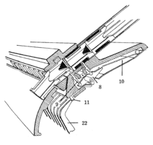
From the assembler, the assembled line moves via the first elevator to the justification vise. The vise has two jaws (1 and 2 in the illustration) which are set to the desired line width. The spacebands are now expanded to justify the line. When the line is justified, the matrices fit tightly between the vise jaws, forming a tight seal which will prevent the molten type metal from escaping when the line is cast.
Justification is done by a spring-loaded ram (5) which raises the tails of the spacebands, unless the machine was equipped with a Star Parts automatic hydraulic quadding attachment or Linotype hydraquadder.[10]
If the operator did not assemble enough characters, the line will not justify correctly: even with the spacebands expanded all the way, the matrices are not tight. A safety mechanism in the justification vise detects this and blocks the casting operation. Without such a mechanism, the result would be a squirt of molten type metal spraying out through the gaps between the matrices, creating a time consuming mess and a possible hazard to the operator.[11] If a squirt did occur, it was generally up to the operator to grab the hell bucket and catch the flowing lead. It was so called because the bucket would often "go to hell", or melt, while holding the molten lead that was still extremely hot. Also, in conjunction with possible hazards facing an operator, toxic lead fumes were possible, as they were the result of melting the lead ingots for casting.
Mold disk and pot

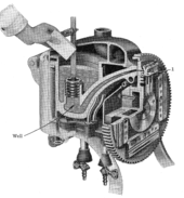
The justification vise holds the assembled line against the face of the mold disk. The mold disk has rectangular openings which correspond to the width and thickness of the slugs (cast lines) to be made. Mold liners fit into these openings for specific slug dimensions.
Behind the mold disk is the type metal pot, which contains molten type metal. A piston in the pot pushes the molten metal down into the pot, which forces the metal through the pot throat and into the mold, forcing it against the faces of the matrices.[12] These have character shapes cut into them, so the result is a cast slug with the character shapes of the line on its front face. The mold disk is sometimes water-cooled, and often air-cooled with a blower, to carry away the heat of the molten type metal and allow the cast slugs to solidify quickly.[13]
When casting is complete, the mold disk turns three-quarters of a turn counterclockwise to the ejector[14] and knife block assembly.[15] The ejector is a rectangular rod that pushes the completed slug from the mold aperture in the mold disk. As it emerges from the mold disk, the slug passes a set of knife edges in the knife block, which trims off any small irregularities in the casting and produces a slug of exactly the desired width and height. From there, the slug drops into the galley tray which holds the lines in the order in which they were cast.[16]
Distribution mechanism

The most significant innovation in the linotype machine was that it automated the distribution step; i.e., returning the matrices and space bands back to the correct place in their respective magazines. This is done by the distributor.
After casting is completed, the matrices are pushed to the second elevator which raises them to the distributor at the top of the magazine. The space bands are separated out at this point and are returned to the spaceband box.[17]
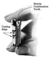
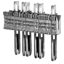
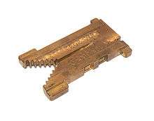
The matrices have a pattern of teeth at the top, by which they hang from the distributor bar. Some of the teeth are cut away; which pattern of teeth is cut away depends on the character on the matrix; i.e., which channel in the magazine it belongs in. Similarly, teeth are cut away along portions of the distributor bar. The bar on the elevator has all teeth, so it will hold any matrix (but not the space bands, which have no teeth at all).
Distributor bar and matrix teeth coding
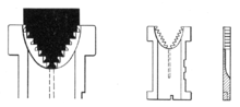
As the matrices are carried along the distributor bar by the distributor screws, they will hang on only so long as there are teeth to hold them. As soon as the matrix reaches the point where each of its teeth corresponds to a cut-away tooth on the distributor bar, it is no longer supported and will drop into the matrix channel below that point.

The pattern of teeth is a 7-bit binary code, with the innermost pair of teeth at the bottom of the notch being the most significant bit. The codes count up from the left side of the main magazine. Code 0 (no teeth) is for spacebands, which are not carried up to the distributor. Code 1 is skipped (no reason for this is given in the Linotype manual). Codes 2 through 92 are for the 91-channel main magazine, and the codes above that are for the auxiliary magazine, if one is installed on the machine. The widest auxiliary magazine has 34 channels, so its rightmost channel is code 125. Code 126 is unused.[18]
Pi matrices
In typesetting, it is sometimes necessary to use characters that are uncommon or obscure enough that it does not make sense to assign them to a magazine channel. These characters are referred to as pi characters or sorts ("pi" in this case refers to an obscure printer's term relating to loose or spilled type). Footnote marks, rarely used fractions, and mathematical symbols are examples of pi characters. In the linotype machine, a pi matrix has all teeth present (code 127, no teeth cut away) so it will not drop from the distributor bar and will not be released into either the main or the auxiliary magazine. Instead, it travels all the way to the end and into the flexible metal tube called the pi chute and is then lined up in the sorts stacker. From the sorts stacker, the machine operator can (manually) pick pi matrices and insert them into the line being assembled as needed.[19]
See also
Notes
- ↑ Lyle L. Miller (1959), Maintaining Reading Efficiency, Holt, p. 34: "The snailpaced process took so many men and so much type that daily newspapers were limited to eight pages".
- ↑ a chapter 1, page 3.
- ↑ a chapter 4, page 57.
- ↑ a chapter 4, page 62.
- ↑ a chapter 3, page 48.
- ↑ a chapter 4, page 59.
- ↑ a chapter 4, page 64.
- ↑ a chapter 6, page 85.
- ↑ "Typesetting" film in the Internet Archive
- ↑ Linotype Hydraquadder Parts Catalog Number 58
- ↑ a chapter 11, pages 123–130.
- ↑ a chapter 13, pages 152–212.
- ↑ a chapter 12, page 134.
- ↑ a chapter 14, pages 213–218.
- ↑ a chapter 15, pages 219–225.
- ↑ a chapter 16, pages 226–231.
- ↑ a chapter 17, pages 232–249.
- ↑ a chapter 20, pages 269–275.
- ↑ a chapter 1, page 36.
References
- ^ Mergenthaler Linotype Company (1940). Linotype Machine Principles. Brooklyn, NY.
- Basil Kahan: Ottmar Mergenthaler – The Man and his Machine; Oak Knoll Press, New Castle (DE), 2000 – ISBN 1-58456-007-X
External links
| Wikimedia Commons has media related to Linotype. |
| Wikisource has the text of the 1921 Collier's Encyclopedia article Linotype. |
- Linotype: The Film – In Search of the Eighth Wonder of the World (Doug Wilson, 2012) is a feature-length documentary centered around the Linotype type casting machine.
- "Farewell, Etaoin Shrdlu". short film about history of Linotype and transition to modern methods. New York Times, 2016-10-14.
- The Printing (Holmes Burton Films Inc., 1947) documentary about linotype tech. in printing industry
- Metal Type—"For Those who Remember Hot Metal Typesetting"
- Intertype Book of Instruction is a complete manual on the operation and maintenance of the Intertype linotype machines
- Linotype Machine on Woodsidepress.com
- Linecast typesetting service at linotypesetting.com
- Typesetting: Linotype vocational instruction film: part 1 and part 2.
- Video of a Linotype being operated in Iowa on YouTube
- 1/13/1894;The Linotype a Machine To Supersede Typesetting
- The 1966 Automatically Controlled Elektron (ACE) Linotype, Teletype, Intertype and more
- Linotype machine patents
- E-book “Linotype – Chronik eines Firmennamens” (in German); (“Linotype – Chronologie of a Company Name”)
| Ways to make impressions |
|  | |||||||||
|---|---|---|---|---|---|---|---|---|---|---|---|
| Typesetting |
| ||||||||||
| Printing press |
| ||||||||||
| Other equipment | |||||||||||