Instrument landing system localizer


Instrument landing system localizer (short: localizer [LOC or LLZ]) is a system of horizontal guidance in the instrument landing system, which is used to guide aircraft along the axis of the runway.
Each radio station or system shall be classified by the service in which it operates permanently or temporarily.
- See also
- Main articles: Radio station and Radiocommunication service
Principle of operation
In aviation, a localizer is the lateral component of the instrument landing system (ILS) for the runway centreline when combined with the vertical glide slope, not to be confused with a locator, although both are parts of aviation navigation systems.
A localizer (like a glideslope) works as a cooperation between the transmitting airport runway and the receiving cockpit instruments. An older aircraft without ILS receiver cannot take advantage of any ILS facilities at any runway, and much more important, the most modern aircraft have no use of their ILS instruments at runways which lack ILS facilities. In parts of Africa and Asia large airports may lack any kind of transmitting ILS system. Some runways have ILS only in one direction, this can however still be used (with a lower precision) known as back beam or "Back Course" which is not associated with a glide slope.
Carrier frequency pairings for localizer and glide slope
Two signals are transmitted on one of 40 ILS channels. One is modulated at 90 Hz, the other at 150 Hz. These are transmitted from co-located antennas. Each antenna transmits a narrow beam.
Localizer (LOC) and glide slope (G/S) carrier frequencies are paired so that the navigation radio automatically tunes the GS frequency which corresponds to the selected LOC frequency. The LOC signal is in the 110 MHz range while the G/S signal is in the 330 MHz range.[1]
LOC carrier frequencies range between 108.10 MHz and 111.95 MHz (with the 100 kHz first decimal digit always odd, so 108.10, 108.15, 108.30, etc., are LOC frequencies and are not used for any other purpose). See Instrument Landing System (ILS) Frequencies on even-numbered TACAN channels from 18X to 56Y.
Localizer in cockpit
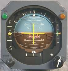
The localizer indicator is (on most aircraft manufactured from the late 1950s) shown below the Attitude Indicator, but is still a part of this instrument together with the glideslope indicator and the cross in the center of the instrument which is called Flight Director.
The glideslope scale is located to the right of the attitude sphere. NB! On aircraft which have a gyro compass (i.o.w. in newer cockpits without video screens or very old ones) are both the localiser and glideslope indicated as a vertical and a horizontal arrow in the compass as well. But they are essentially read in the same way. On some aircraft is only the glideslope indicated on two main instruments, and the oldest version of ILS-instruments was an instrument of its own used instead. This used two dangeling bars, fixed in the middle of the top (localizer indicator) and in the middle of the left side (glideslope indicator), and if the aircraft was located on the intended glidepath, the dangeling bars formed a cross. This is more difficult to learn, but even for pilots with long experience of using that kind of indicators, it meant that the pilot needed to read one gauge more. With the indicators added to the artificial horizon (and to the compass), the pilot can watch the attitude simultaneously with the localiser and glideslope.
In modern cockpits, the localizer is seen as a colored dot (usually in the shape of a diamond) at the bottom of the artificial horizon gauge. It does not appear during cruise, but comes up during the descent and approach to the selected runway, provided that the navigation radio is set to the ILS frequency of that specific runway. If the transmitted localizer beam, which usually, but not always, is directed in the heading of the runway extension. (exceptions exist f.i. in Innsbruck, Austria and in Macao, China) If the aircraft is located on this line, the localizer dot will appear in the middle of the scale. But if the aircraft is located a little left of the beam, the marker will appear to the right on the localizer gauge scale in cockpit. The pilot then knows he or she must adjust the heading towards the dot.
In older cockpits, the localizer scale below the artificial horizon is rather short. But in older style cockpit instrumentation, the localizer also appears as an arrow in the gyro compass below the artificial horizon. The top and bottom of this arrow "is one unit", which shows current heading. But the middle part of this arrow is moving independently of the aircraft's heading. The middle of that arrow could be described as being "stand alone", and moves to the left if the aircraft is located to the right of localizer beam and to the right if the aircraft is located to the left of the localizer beam. When the arrow is "united" to a straight line, then the aircraft is following the localizer beam. (This second "arrow-indicator" is omitted in modern cockpits, but the main compass is still located below the artificial horizon)
At previously mentioned exceptions of runways, where the ILS beam is not leading all the way to the runway, the runway needs to be visible before the final approach begins.
The very first generation of localizer gauges had a different cockpit interface, and were not included in the artificial horizon nor any compass, but at a gauge of its own. The localizer was then represented as a dangling stick hanging from a fixed point at the top of a separate gauge, and the glideslope was represented by a similar, but horizontal, dangling stick, fixed at one of the sides of the gauge. When the aircraft was located exactly at the ILS-beam (or glidepath) the two sticks formed a cross. This interface resembles the flight director, which also forms a cross, but on the artificial horizon. This older ILS instrumentation system was omitted around the same time as jet airliners like Boeing 707 and DC 8 were introduced.
The expression "Catch the localizer" refers to runway approaches with the autopilot on. The angle between the aircraft heading and localizer beam should be less than 30 degrees, and the indicated airspeed at least below 250 knots (for jet airliners), then by pushing a button marked "APP" or "ILS", then the autopilot presumably will turn and then follow the localizer. The autopilot will then also automatically descend according to the glideslope. Normal procedure is to catch the localizer first and then follow the glideslope as well. If the angle is too large or the airspeed too high, catching the localizer might fail.
Modern aircraft can land "themselves", provided the runway ILS is of sufficient standard (class III C) and the cross wind component is low. Pure autolandings are mostly done in foggy weather.
The cockpit ILS gauges is not to be confused with the flight director, which also is located on the artificial horizon gauge. A flight director only shows how the autopilot would fly. If the localizer dot (or arrow) indicate runway is to be found to the left, but the flight director suggests a right turn, and the runway isn't visible, then the pilot in command is having difficulties.
Some runways have ILS beams intended for use in one direction only. However, as the localizer beam by its nature also goes backwards, it can still be of some use. This is called back beam. It's of help during the approach, but the use of back beam localizer gives less precision compared to normal use.
Localizer at runways
When the glideslope is unserviceable, the localizer element can often be conducted as a separate non-precision approach, abbreviated to 'LOC'. A standalone instrument approach installation without an associated glidepath carries the abbreviation 'LLZ'.
In some cases, a course projected by localizer is at an angle to the runway (usually due to obstructions near the airport). It is then referred to as a localizer type directional aid (LDA). The localizer system is placed about 1,000 feet from the far end of the approached runway. Usable volume extends to 18 NM for a path up to 10° either side of runway centerline. At an angle of 35° either side of runway centerline, the useful volume extends up to 10 NM. Horizontal accuracy increases as distance between the aircraft and localizer decreases. Localizer approach specific weather minimums are found on approach plates.
Specifications
- Course line (CL) is where difference in the depth of modulation (DDM) is zero in the horizontal plane.
- Course sector (CS) is the sector in the vertical plane bounded by DDM = 0.155.
- Displacement sensitivity (DS) is the change in DDM per meter at ILS reference datum (the runway threshold) and should be 0.00145 (hence CS is 106.9m at threshold).
- Clearance: from the angle where the DDM is 0.180 to 10° from CL, the DDM shall not be less than 0.180; from 10° to 35° from CL the DDM shall not be less than 0.155.
- Coverage: at 25 nmi (46 km) within 10° from CL; at 17 nmi (31 km) within 10° and 35° from CL; at 10 nmi (19 km) outside 35° if coverage is required.
- Reduced coverage: at 18 nmi (33 km) within 10° from CL; at 10 nmi (19 km) within 10° and 35° from CL.
- Mean course line at ILS reference datum (threshold) shall be adjusted and maintained within:
- CAT I: ± 10.5m (15μA)
- CAT II: ± 7.5m (11μA) (recommended ± 4.5m (6.4μA))
- CAT III: ± 3.0m (4.3μA)
- The DS shall be adjusted and maintained within:
- CAT I: ± 17%
- CAT II / III: ± 10%
See also
- AN/MRN-1
- Andrew Alford
- Instrument approach
- Instrument landing system
- Localizer type directional aid
- Simplified directional facility
References
- ↑ "Frequency allotments" (PDF). ntia.doc.gov. January 2008. Retrieved 28 September 2010.
- Aeronautical Information Manual, published in US by Federal Aviation Administration