Attitude indicator
An attitude indicator (AI), also known as gyro horizon or artificial horizon or attitude director indicator (ADI, when it has a Flight Director), is an instrument used in an aircraft to inform the pilot of the orientation of the aircraft relative to Earth's horizon. It indicates pitch (fore and aft tilt) and bank (side to side tilt) and is a primary instrument for flight in instrument meteorological conditions.
Attitude indicators are also used on manned spacecraft and are called, Flight Director Attitude Indicator (FDAI), where they indicate the craft's yaw angle (nose left or right) as well as pitch (nose up or down), roll, and orbit relative to a fixed-space inertial reference frame.[1] An FDAI, has different modes that allow for known positions relative to Earth or the stars, so that the engineers, scientists and astronauts can communicate the relative position, attitude, and orbit of the craft. [2]
Use
The essential components of the indicator are:[3]
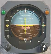
- "miniature airplane", horizontal lines with a dot between them representing the actual wings and nose of the aircraft.
- the center horizon bar separating the two halves of the display, with the top half usually blue in color to represent sky and the bottom half usually dark to represent earth.
- degree indices marking the bank angle. They run along the edge of the dial. On a typical indicator, there is a zero angle of bank index, there may be 10 and 20 degree indices, with additional indices at 30, 60 and 90 degrees.
If the symbolic aircraft dot is above the horizon line (blue background) the aircraft is nose up. If the symbolic aircraft dot is below the horizon line (brown background) the aircraft is nose down. The fact that the horizon moves up and down and turns, while the symbolic aircraft is fixed relative to the rest of the instrument panel, tends to induce confusion in trainees learning to use the instrument; a standard mental corrective provided by flight instructors is "Fly the little airplane, not the horizon."
A 45 degree bank turn is made by placing the indicator equidistant between the 30 and 60 degree marks. A 45 degree bank turn is usually referred to as a steep turn.
The pitch angle is relative to the horizon. During instrument flight, the pilot must infer the total performance by using other instruments such as the airspeed indicator, altimeter, vertical speed indicator, directional gyro, turn rate indicator, and power instruments, e.g. an engine tachometer. "Performance = Attitude + Power".
Most Russian-built aircraft have a somewhat different design. The background display is colored as in a Western instrument, but moves up and down only to indicate pitch. A symbol representing the aircraft (which is fixed in a Western instrument) rolls left or right to indicate bank angle.[4]
It was proposed that a hybrid version of the Western and Russian artificial horizon systems be developed that would be more intuitive than either, although this concept never caught on. [5]
Operation
.svg.png)
Traditional, self-contained attitude indicators use a gyroscope (powered via vacuum or electrically) to establish an inertial platform. The gyroscope is geared to a display that has two degrees of freedom, simultaneously displaying pitch and bank. The display may be colored to indicate the horizon as the division between the two colored segments (typically blue for sky and brown for ground), and is intended to be intuitive to use. The actual bank angle is calibrated around the circumference of the instrument. The pitch angle is indicated by a series of calibration lines, each representing 5° or 10° of pitch depending on design.
The instrument may develop small "precession" errors, in pitch indication during extended periods of acceleration or deceleration and, in bank indication during extended periods in a turn, caused by the mechanism that normally keeps the gyro rotor properly erected. These errors develop very slowly (usually at not more than 2 or 3 degrees per minute) and are not significant in normal flying. Some attitude indicators can only tolerate a specific range of bank angles. If the aircraft rolls too steeply or achieves an extreme pitch attitude — while performing aerobatics, for example — the attitude indicator can "tumble" (or "topple") and become temporarily unusable. For this reason, some attitude indicators are fitted with a "caging mechanism" (a device to restore the gyroscope to an erect position). Some attitude indicators can be manually erected once the airplane is in level flight using the caging mechanism. Most modern instruments are designed to tolerate 360 degrees of rotation in pitch and roll without tumbling, although periods of violent aerobatics may tumble any gyro horizon. Once tumbled, an instrument without a caging mechanism may not be able to re-erect itself until power is removed and the aircraft is in a level pitch and roll attitude for a long enough period that the gyro rotor comes to a stop.
Attitude and Heading Reference Systems (AHRS) are able to provide three-axis information that can be shared with multiple devices in the aircraft, such as "glass cockpit" primary flight displays (PFDs). Rather than using a spinning rotor for the horizon reference, modern AHRS use 3-dimension magnetometers and accelerometers to detect the airplane's pitch and roll attitude. AHRS have been proven to be highly reliable and are in wide use in commercial and business aircraft. Recent advances in MEMS manufacturing have brought the price of FAA-certified AHRS down to less than $15,000, making them practical for general aviation aircraft.
With most AHRS systems, if an aircraft's AIs have failed there will be a standby AI located in the center of the instrument panel, where other standby basic instruments such as the airspeed indicator and altimeter are also available. These mostly mechanical standby instruments may be available even if the electronic flight instruments fail, though the standby attitude indicator may be electrically driven and will, after a short time, fail if its electrical power fails.[6]
See also
- Acronyms and abbreviations in avionics
- Peripheral vision horizon display (PVHD)
- Turn coordinator
- Turn and bank indicator
- Korean Air Cargo Flight 8509
References
- ↑ "Flight-Director/Atitude Indicator". www.hq.nasa.gov. Retrieved 2016-12-01.
- ↑ "Apollo Flight Journal - Apollo Operations Handbook. Volume 1.". history.nasa.gov. Retrieved 2016-12-01.
- ↑ http://www.faa.gov/regulations_policies/handbooks_manuals/aircraft/amt_airframe_handbook/media/ama_ch10.pdf Aircraft Instrument Systems page 10-56
- ↑ Learmount, David (2009-02-09), "Which way is up for Eastern and Western artificial horizons?", flightglobal.com, archived from the original on October 29, 2014
- ↑ Safety expert proposes low-cost loss of control fixes , FlightGlobal, 2011-03-04
- ↑ "NTSB Safety Recommendation". 2010-11-08.