D-17B
The D-17B was the computer used the Minuteman I NS-1OQ missile guidance system.
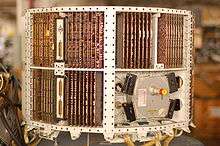
The complete guidance system contained a D-17B computer, the associated stable platform, and power supplies. The D-17B weighed approximately 62 pounds (28 kg), contained 1,521 transistors, 6,282 diodes, 1,116 capacitors, and 504 resistors. These components were mounted on double copper-clad, engraved, gold-plated, glass fiber laminate circuit boards. There were 75 of these circuit boards and each one was coated with a flexible polyurethane compound for moisture and vibration protection. The high degree of reliability and ruggedness of the computer were driven by the strict requirements of the weapons system.
Design constraints
Since an airborne, computer-controlled missile only gets one chance to execute its mission, the design specifications of the D-17B required very high reliability. This was achieved by using DRL (diode-resistor) logic extensively and only using DTL (diode-transistor) logic where gain or inversion was required in this fully solid-state computer. In the early 1960s when the D-17B was designed, transistors were not as reliable as they are now, thus the designers used transistors only when necessary. The rotating disk memory, with non-destructive readout (NDRO), also enhanced the reliability of the computer. In actual, real-time situations involving Minuteman missiles, the mean time between failures (MTBF) was over 5.5 years.
The Soviets had much larger rockets and could use vacuum tubes (thermionic valves) in their guidance systems. (The weights of the minuteman I and II are classified, but the minuteman III was 35,000 kg versus the Soviet R-7 missile (1959) of 280,000 kg.) The US planners had to choose between developing solid state guidance systems and the considerable cost and time delay of developing larger rockets.
Specifications
Minuteman I D-17B Computer Specifications
Year: 1962
The D17B is a synchronous serial general-purpose digital computer.
Manufacturer: Autonetics Division of North American Aviation
Applications: Guidance and control of the Minuteman I ICBM.
Programming and numerical system:
- Number system: Binary, fixed point, 2's complement
- Logic levels: 0 or False, 0V; 1 or True, -10V
- Data word length (bits): 11 or 24 (double precision)
- Instruction word length (bits): 24
- Binary digits/word: 27
- Instructions/word: 1
- Instruction type: One and half address
Number of instructions: 39 types from a 4-bit op code by using five bits of the operand address field for instructions which do not access memory.
Execution times:
- Add (microseconds): 78 1/8
- Multiply (µs): 546 7/8 or 1,015 5/8 (double precision)
- Divide: (software)
(Note: Parallel processing such as two simultaneous single precision operations is permitted without additional execution time.)
Clock channel: 345.6 Hz
Addressing:
- Direct addressing of entire memory
- Two-address (unflagged) and three-address (flagged) instructions
Memory:
- Word length (bits): 24 plus 5 timing
- Type: Ferrous-oxide-coated NDRO disk
- Cycle time (µs): 78 1/8 (minimal)
- Capacity (words): 5,454 or 2,727 (double precision)
Input/output:
- Input lines: 48 digital
- Output lines: 28 digital
- 12 analog
- 3 pulse
- Program: 800 5-bit char/s
Instruction word format:
    +--------+--------+------+--------+---------+--------+--------+
    |   TP   | T24 21 | 20   | 19  13 | 12    8 | 7    1 |   0    |
    +--------+--------+------+--------+---------+--------+--------+
    | Timing | OP     | Flag | Next   | Channel | Sector | Timing |
    |        |        |      | Inst.  |         |        |        |
    |        |        |      | Sector |         |        |        |
    +--------+--------+------+--------+---------+--------+--------+
Registers:
- Phase and voltage output registers
Arithmetic unit (excluding storage access):
- Add: 78 µs
- Multiply: 1,016 µs
Construction (arithmetic unit only): transistor-diode logic is used.
- Timing: Synchronous
- Operation: Sequential
| Medium | No. of Words | Access (µs) | |
|---|---|---|---|
| Rotating disk | 2,688 | 5,000 avg. | (general purpose channels) |
| Rotating disk | 41 | (rapid access loops) | |
| 40 | (1 word loop) | ||
| 160 | (4 word loop) | ||
| 320 | (8 word loop) | ||
| 640 | (16 word loop) |
Input
- 48 digital lines (input)
- 26 specialized incremental inputs
   -Medium-             -Speed-
   Paper/Mylar Tape      600 chars/sec
   Keyboard              Manual
   Typewriter            Manual
OUTPUT
   -Medium-              -Speed-
   Printer Character     78.5–2,433 ms   (Program Control)
   Phase - Voltage       (Program Control)
28 digital lines (output) 12 analog lines (output) 13 pulse lines (output) 25,600 word/s maximum I/O transfer rate
Physical characteristics
- Dimensions: 20 in high, 29 in diameter, 5 in deep
- Power: 28 VDC at 25 A
- Circuits: DRL and DTL
- Weight: 62 pounds (28 kg)
Construction:
- Double copper clad, gold plated, glass fiber laminate, flexible polyurethane-coated circuit boards
Software:
- Minimal delay coding using machine language
- Modular special-purpose subroutines
Reliability: 5.5 years MTBF
Checking features: Parity on fill and on character outputs
Power, space, weight, and site preparation
- Power, computer: 0.25 kW
- Air conditioner: Closed system
- Volume, computer: 1.55 cu ft (44 L)
- Weight, computer: 70 lb (32 kg)
- Designed specifically to fit in cylindrical guidance package.
The word length for this computer Is 27 bits, of which 24 are used In computation. The remaining 3 bits are spare and synchronizing bits. The memory storage capability consists of a 6000 rpm magnetic disk with a storage capacity of 2985 words of which 2728 are addressable. The contents of memory include 20 cold-storage channels of 128 sectors (words) each, a hot-storage channel of 128 sectors, four rapid access loops (U,F,E,H) of 1, 4, 8, and 16 words respectively, four 1-word arithmetic loops (A, L,H,I), and a two 4-word input buffer input loops (V,R).
The outputs that can be realized from the D-17B computer are binary, discrete, single character, phase register status, telemetry, and voltage outputs. Binary outputs are computer generated levels of +1 or −1 available on the binary output lines.
Instruction set
D-17B Instruction Repertoire

Numeric Code		Code	Description
------------		----	-----------
00 20, s 		SAL 	Split accumulator left shift
00 22, s 		ALS 	Accumulator left shift
00 24, 2 		SLL 	Split left word left shift
00 26, r 		SLR 	Split left word right shift
00 30, s 		SAR 	Split accumulator right shift
00 32, s 		ARS 	Accumulator right shift
00 34, s 		SRL 	Split right word left shift
00 36, s 		SRR 	Split right word right shift
00 60, s 		COA 	Character output A
04  c, S 		SCL 	Split Compare and .ivt
10  c, S 		TMI 	Transfer on minus
20  c, s 		SMP 	Split multiply
24  c, s 		MPY 	Multiply
30  c, s 		SMM 	Split multiply modified
34  c, s 		MPM 	Multiply modified
40 02, s 		BOC 	Binary output C
40 10, s 		BCA 	Binary output A
40 12, s 		BOB 	Binary output B
40 20, s 		RSD 	Reset detector
40 22, s 		HPR 	Halt and Proceed
40 26, s 		DOA 	Discrete output A
40 30, s 		VOA 	Voltage output A
40 32, s 		VOB 	Voltage output B
40 34, s 		VOC 	Voltage output C
40 40, s 		ANA 	And to accumulator
40 44, s 		MIM 	Minus magnitude
40 46, s 		COM 	Complement
40 50, s 		DIB 	Discrete input B
40 52, s 		DIA 	Discrete input A
40 60, s 		HFC 	Halt fine countdown
40 70, s 		LPR 	Load phase register
44  c, s 		CIA 	Clear and Add
50  c, s 		TRA 	Transfer
54  c, s 		STO 	Store accumulator
60  c, s 		SAD 	Split add
64  c, s 		ADD 	Add
70  c, s 		SSU 	Split subtract
74  c, s 		SUB 	Subtract

Special features of the D-17B computer include flag store, split-word arithmetic, and minimized access timing. Flag store provides the capability of storing the present contents of the accumulator while executing the next Instruction. Split-word arithmetic is used in performing arithmetic operations on both halves of a split word at the same time. A split word on the D-17B consists of 11 bits. Minimized access timing is the placing of instructions and data in memory so that they are available with minimum delay from the disk memory.
Guidance software
Autonetics was the associate contractor for the Minuteman (MM) guidance system, which included the flight and prelaunch software. This software was programmed in assembly language into a D17 disk computer. TRW provided the guidance equations that Autonetics programmed and was also responsible for the verification of the flight software. When MM I became operational, the flight computer was the only digital computer in the system. The targeting was done at Strategic Air Command (SAC) Headquarters by the Operational Targeting Program developed by TRW to execute on an IBM 709 mainframe computer.[1]
Sylvania Electronics Systems was selected to develop the first ground-based command and control system using a programmable computer. They developed the software, the message processing and control unit for Wing 6. To support the deployment of the Wing 6 system, TRW, Inc. developed the execution plan program (EPP) from a mainframe computer at SAC and performed an independent checkout of the command and control software. The EPP assisted in assigning targets and launch time for the missiles.[2]
The MM II missile was deployed with a D-37C disk computer. Autonetics also programmed functional simulators and the code inserter verifier that was used at Wing headquarters to generate and test the flight program codes to go into the airborne computer.[2]
Notes
- ↑ Tony C. Lin. "Development of U.S. Air Force Intercontinental Ballistic Missile Weapon Systems." Journal of Spacecraft and Rockets, vol. 40, no. 4, 2003. Pp. 491-509
- 1 2 Lin, Pp. 491-509
References
- Autonetics Division of North American Rockwell. Inc.; Minuteman D-17 Computer Training Data. Anaheim, California, 8 June 1970.
- Autonetics Division of North American Rockwell. Inc.; Part I - Preliminary Maintenance Manual of the Minuteman D-17A Computer and Associated Test Equipment. P.O. Memo 71. Anaheim, California, Inc., January 1960.
- Beck, C.H. Minuteman Computer Users Group, Report MCUG-l-71. New Orleans, Louisiana: Tulane University, April 1971.
- Beck, C.H. Minuteman Computer Users Group. D-17B Computer Programming Manual. Report MCUG-4-71. New Orleans. Louisiana: Tulane University, September 1971.
- Beck, Charles H. Investigation of Minuteman D-17B Computer Reutilization. Available from NTIS/DTIC as document AD0722476, January 1971, 54 pp.
- Lin, Tony C.; "Development of U.S. Air Force Intercontinental Ballistic Missile Weapon Systems." Journal of Spacecraft and Rockets, vol. 40, no. 4, 2003. pp. 491–509.
- Weik, Martin H.; A Fourth Survey of Domestic Electronic Digital Computing Systems. Ballistic Research Laboratories, Aberdeen Proving Ground, MD, Report No. 1227, January 1964.