Coast Artillery fire control system
In the U.S. Coast Artillery,[1] the term fire control system was used to refer to the personnel, facilities, technology and procedures that were used to observe designated targets, estimate their positions, calculate firing data for guns directed to hit those targets, and assess the effectiveness of such fire, making corrections where necessary.[2]
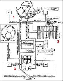
In brief, the fire control system in use from about 1900 through WW2 involved observers, often situated in base end stations, using optical instruments (like azimuth telescopes or depression position finders) to measure bearings and/or distances to targets (usually moving ships).[3] Both horizontal and vertical base position finding systems were used.[4] These observations were communicated to personnel in battery plotting rooms, who used a mechanical device called a plotting board to indicate the target's observed location on a map of the area. The red "1" on the diagram at right indicates this first stage of the fire control process.
Once several positions had been plotted for the target (blue circles on Figure 1 at left), plotting board operators estimated the position of the target at the instant a salvo, fired by the battery, was expected to land. This position was called the set forward point (green square in Figure 1), since it involved "setting forward" the target's expected position (assuming continued forward travel at the same speed and in the same direction) during two intervals of time: (1) the dead time between the time the observation had been made and the time the guns were actually fired at that target plus (2) the time of flight--the time the projectile spent in the air before hitting something. The set forward point was expressed in terms of firing data: a range (in yards) and an azimuth (a compass heading in degrees)[5] at which the gun/s should be pointed by the gun crews in order to hit the target.
Before these firing data were sent to the guns, however, they were corrected for a variety of "non-standard conditions", like temperature (which affected the explosive power of the powder charge) or wind strength and direction (which affected the flight of the projectile). The red "2" in the diagram at right indicates this stage in the fire control process. Special devices, like the deflection board (for corrections in azimuth) or the range correction board (for corrections in range) were used to produce corrected firing data.[6]
The final stage (the red "3" in the diagram at right) had to do with using feedback from the battery's observers, who spotted the fall of the projectiles (over or under range, left or right in azimuth, or on target) and telephoned their data to the plotting room so that the aim of the guns could be corrected for future salvos.[7]
The importance of timing

Fire control in the Coast Artillery involved a sequence of steps that was carried out over and over again while a target was being tracked and fired upon. First, observers sighted on the target and sent their observations to the plotting room. Next, plotters calculated the target's position and probable future movement, as well as adjustments to range and azimuth (direction). Then firing data were sent to the batteries and used by gun crews to point their guns. The guns were fired. Finally, spotters might spot the fall of the projectiles, sending this information back to the plotting room for use in correcting fire. After this, observers would sight on the (new) position of the target, beginning another cycle. The time period between sequential sightings by the observers was called the observing interval.[8] It was typically set at 20 sec. for controlling batteries of larger guns.[9]
Not only did everyone in the fire control system have to stay in synch (for example, knowing which one of a series of sets of fire control data they were working with at any given time) but certain functions (notably the making of target sightings by the observers and the firing of the guns by the gun crews) had to be carried out at precise intervals if the accuracy of the system was to be maintained.
To enable all battery personnel to stay in synch, a time interval bell (or buzzer) would be rung in every observation or spotting station serving the battery, in the plotting room, and at each gun, using bells or buzzers wired together with a centrally located master clock.[10] Five seconds before the start of the next cycle, the bell would ring. After a one second delay, it would ring again. And after another one-second gap the bell would ring a third time, and on this third ring the observations were made again and/or the guns were fired.
A well trained battery could observe, plot, adjust, and transmit the firing data to its guns, which could then be loaded and laid, all before the next 20-second bell, at which point the guns would be fired.[11] If for some reason the firing data were not received in time by the guns, or if a hold-up or a misfire occurred, then firing happened at the end of the following interval. In such a case, the command "Relay!" (re-lay) was given at the guns.[12]
See also
- List of U.S. Army fire control and sighting material by supply catalog designation
- Gun Data Computer
- Fire-control system
- Seacoast defense in the United States
References
- ↑ The U.S. Coast Artillery Corps was created in 1907, separated from the Field Artillery Corps as part of the U.S. Army artillery. It was abolished in 1950. Over the 35 years of its most active period (about 1905 to 1940), the coast artillery system in the United States involved over 2,000 guns and mortars of 3-inch caliber or greater, defending some 30 locations (generally harbors) across the country. Designed to protect major U.S. harbors against attack from the sea, the coast artillery system in the continental United States never actually fired upon an enemy target. By 1942, with the course of WW2 turning in the Allies' favor, the Coast Artillery was scaled back, and was dissolved altogether in 1946.
- ↑ For a complete description of fire control in the Coast Artillery, see "FM 4-15 Coast Artillery Field Manual-Seacoast Artillery Fire Control and Position Finding," U.S. War Department, Government Printing Office, Washington, 1940.
- ↑ During WW2, the M8 gun data computer emerged. This trailer-mounted electro-mechanical computer required the same observations as the earlier system. But now telephone operators linked to the observers entered position data to the computer by turning hand wheels, instead of shouting them out to operators on the plotting board. Triangulation, correction of firing data, and relocation to particular guns was handled by the computer, much more quickly and accurately than by the older, manual methods.
- ↑ See Bolling W. Smith, "Vertical and Horizontal-Base Position Finding Systems," The Coast Defense Study Group Journal, Vol. 13, Issue 3, August, 1999.
- ↑ In the U.S. Coast Artillery, azimuths were expressed as bearings with reference to true South as opposed to true North.
- ↑ Coast Artillery manuals and publications between 1910 and 1940 describe many different instruments, devices, scales and schedules that were proposed and adopted for correcting (before firing) and adjusting (after firing) firing data. Many pieces of fire control equipment had to be made specific to just one type of gun or another and/or for each different type of ammunition. A useful source is the Coast Artillery Journal. See the on-line index.
- ↑ Prior to about 1920, little use seems to have been made of spotting data, the guns being fired on the basis of direct sighting from the gun commander's position or plotting board calculations, corrected for non-standard conditions. The argument was made that adjusting these data for the fall of fire simply slowed down gun-laying and introduced a new source of error into the system. See "Seacoast Artillery Firing," in the "Coast Artillery Journal," Vol. 63, No. 4, October, 1925.
- ↑ Supra, Note 2, Chapter 6.
- ↑ Larger guns here refers to guns of more than 3-inch caliber.
- ↑ In WW2, the time interval "bell" could also be a tone injected over a telephone line. For a description of the timing equipment, see Bolling W. Smith, "WW-II Time Interval Systems," The Coast Defense Study Group Journal, Vol. 10, May 1966, p. 76
- ↑ The example in Figure 1 above assumes that a longer time is needed to lay and fire the guns, so the set forward point is computed based upon Observation #4 and firing does not occur until the end of observing interval #6. Establishing a longer firing interval or "skipping" an interval as above for a given battery was often done if battery personnel were not skillful enough to fire on the shorter interval.
- ↑ Sometimes interim firing data would be sent to the guns between the primary intervals, enabling gunners to set up their guns more quickly or fire additional salvos at important targets.
Bibliography
- Berhow, Mark A., Ed. (2015). American Seacoast Defenses, A Reference Guide, Third Edition. McLean, Virginia: CDSG Press. ISBN 978-0-9748167-3-9.
External links
- Coast Defense Study Group website
- FM 4-15, Seacoast Artillery Fire Control and Position Finding