Wireless telegraphy


Wireless telegraphy is the transmission of electric telegraphy signals without wires (wirelessly). It is now used as a historical term for early radio telegraphy systems which communicated with radio waves, although when the term originated in the late 19th century it was also used for a variety of other experimental techniques for communicating telegraphically without wires, such as photoelectric and induction telegraphy.[1][2]
Wireless telegraphy came to mean Morse code transmitted by radio waves (electromagnetic waves), initially called "Hertzian waves", discovered by Heinrich Hertz in 1886. The first practical wireless telegraphy transmitters and receivers were developed by Guglielmo Marconi beginning in 1895. By 1910 communication by Hertzian waves was universally referred to as "radio",[3] and the term wireless telegraphy has been largely replaced by the more modern term "radiotelegraphy". The transmission of speech (radiotelephony) began to displace wireless telegraphy by the 1920s for many applications, making possible radio broadcasting. Wireless telegraphy continued to be used for private point-to-point business, governmental, and military communication, such as telegrams and diplomatic communications, and evolved into radioteletype networks. Continuous wave (CW) radiotelegraphy is regulated by the International Telecommunication Union (ITU) as emission type A1A.
Today, due to more modern text transmission methods, Morse code radiotelegraphy for commercial use has become obsolete. On shipboard the computer and satellite linked GMDSS system has largely replaced Morse as a means of communication. Telegraphy is taught on a very limited basis by the military.[4] A CW coastal station, KSM, still exists in California, run primarily as a museum by volunteers,[5] and occasional contacts with ships are made. Radio beacons, particularly in the aviation service, but also as "placeholders" for commercial ship-to-shore systems, also transmit Morse but at very slow speeds.
The US Federal Communications Commission does still issue a lifetime commercial Radiotelegraph Operator License. This requires passing a simple written test on regulations, a more complex written exam on technology, and demonstrating Morse reception at 20 words per minute plain language and 16 wpm code groups. (Credit is given for amateur extra class licenses earned under the old 20 wpm requirement.)[6] Wireless telegraphy is still used widely today by amateur radio hobbyists where it is commonly referred to as radio telegraphy, continuous wave, or just CW. However its knowledge is not required to obtain any class of amateur license.
History of development
Ground and water conduction
A number of wireless electrical signaling schemes including electric currents through water and the ground were investigated for telegraphy before practical radio systems became available.
The original telegraph used two wires between two stations to form a complete electrical circuit or "loop." In 1837, however, Carl August von Steinheil of Munich, Germany found that by connecting one leg of the apparatus at each station to metal plates buried in the ground, he could eliminate one wire and use a single wire for telegraphic communication. This led to speculation that it might be possible to eliminate both wires and therefore transmit telegraph signals through the ground without any wires connecting the stations. Other attempts were made to send the electric current through bodies of water, in order to span rivers, for example. Prominent experimenters along these lines included Samuel F. B. Morse in the United States and James Bowman Lindsay in Great Britain, who in August 1854, was able to demonstrate transmission across a mill dam at a distance of 500 yards (457 metres).[7]
Telegraphic communication using earth conductivity was eventually found to be limited to impractically short distances, as was communication conducted through water, or between trenches during World War I.
Optical
The first wireless voice telecommunication device, invented in 1880, was the photophone, which carried voice communications optically on a lightbeam transmitted to a distant receiver.
Electrostatic and electromagnetic
Both electrostatic and electromagnetic induction were used to develop wireless telegraph systems that saw limited commercial application. In the United States, Thomas Edison, in the mid-1880s, patented an electromagnetic induction system he called "grasshopper telegraphy", which allowed telegraphic signals to jump the short distance between a running train and telegraph wires running parallel to the tracks.[8] This system was successful technically but not economically, as there turned out to be little interest by train travelers in an on-board telegraph service. During the Great Blizzard of 1888, this system was used to send and receive wireless messages from trains buried in snowdrifts. The disabled trains were able to maintain communications via their Edison induction wireless telegraph systems,[9] perhaps the first successful use of wireless telegraphy to send distress calls.
The most successful creator of an electromagnetic induction telegraph system was William Preece in the United Kingdom. Beginning with tests across the Bristol Channel in 1892, Preece was able to telegraph across gaps of about 5 kilometres (3.1 miles). However, his induction system required extensive lengths of antenna wires, many kilometers long, at both the sending and receiving ends. The length of those sending and receiving wires needed to be about the same length as the width of the water or land to be spanned. For example, for Preece's station to span the English Channel from Dover, England, to the coast of France would require sending and receiving wires of about 30 miles (48 kilometres) along the two coasts. These facts made the system impractical on ships, boats, and ordinary islands, which are much smaller than Great Britain or Greenland. In addition, the relatively short distances that a practical Preece system could span meant that it had few advantages over underwater telegraph cables.
Electromagnetic wave (radio)
Wireless telegraphy dates as far back as Faraday in the early 19th century, when it was discovered that radio waves could be used to send telegraph messages.
In the mid-1860s, James Clerk Maxwell predicted the existence of electromagnetic waves and showed that their propagation speed is identical to that of light. After that, in reality, it required very little to demonstrate by experiment the existence of such waves.
Calzecchi-Onesti
By 1884, Temistocle Calzecchi-Onesti in Fermo, Italy, developed a primitive device that responded to radio waves.[10] It consisted of a tube filled with iron filings, called a "coherer". This kind of device would later be developed to become the first practical radio detector. Writing in the Rendiconti of the Lombardy Institution[11] regarding the discovery of the coherer, directs attention to his experiments made in 1884, before Branly had worked on the subject. He further points out the part played by Augusto Righi in wireless telegraphy.[12]
Calzecchi found that the conductivity of metal powder varied depending on the incidence of radio waves.[13] However, Calzecchi's experiments were not widely reported.[13] He would later write Le mie esperienze e quelle di Edoardo Branly: Sulla conduttività elettrica delle limature metalliche[14] (tr., "My experiences and those of Edward Branly: The electrical conductivity of metal filings").
Heinrich Hertz
Between 1886 and 1888, Heinrich Rudolf Hertz[15] studied Maxwell's theory and validated it through experiment.[16] He demonstrated the transmission and reception of the electromagnetic waves predicted by Maxwell, and he intentionally transmitted and received radio. Hertz changed the frequency of his radiated waves by altering the inductance or capacity of his radiating conductor or antenna, and reflected and focused the electromagnetic waves, thus demonstrating the correctness of Maxwell's electromagnetic theory of light.[17] Famously, he saw no practical use for his discovery.
In his Ultra high frequency (UHF) experiments, Hertz transmitted and received radio waves over short distances and showed that the properties of radio waves were consistent with Maxwell’s electromagnetic theory. He demonstrated that radio radiation had all the properties of waves (now called electromagnetic radiation), and discovered that the electromagnetic equations could be reformulated into a partial differential equation called the wave equation.
He demonstrated the existence of electromagnetic radiation (radio waves) in a series of experiments in Germany during the 1880s. Hertz showed methods of producing, detecting, and measuring these waves. It had been known for many years – from the predictions of Kelvin and Von Helmholtz, and confirmed by the experiments of Fedderssen – that in many cases an electric discharge is of an oscillatory character. In the years 1887-8, Lodge, Fitzgerald, and others were investigating the nature of these oscillations, and the manner in which they are guided by conducting wires, when Hertz conceived the idea of investigating the disturbances caused by such oscillatory discharges in the surrounding space.
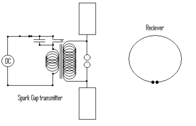
Hertz used the damped oscillating currents in a dipole antenna, triggered by a high-voltage electrical capacitive spark discharge, as his source of radio waves. His detector in some experiments was another dipole antenna connected to a narrow spark gap, thereby creating a spark-gap transmitter. A small spark in this gap signified detection of the radio waves. When he added cylindrical reflectors behind his dipole antennas, Hertz could detect radio waves about 20 metres (22 yards) from the transmitter in his laboratory at the Karlsruhe Technical High School. He did not try to transmit further because his aim was proving electromagnetic theory, not developing wireless communication.
In the collection of physical instruments in Karlsruhe, Hertz had found and used for lecture purposes a pair of so-called Eiess spirals or Knochenhauer spirals. Hertz had been surprised to find that it was not necessary to discharge large batteries through one of these spirals in order to obtain sparks in the other; small Leyden jars amply sufficed for this purpose, and even the discharge of a small induction coil would do, provided it had to spring across a spark gap. In altering the conditions, Hertz came upon the phenomenon of side-sparks, which formed the starting point of his research. At first Hertz thought the electrical disturbances would be too turbulent and irregular to be of any further use, but when he had discovered the existence of a neutral point in the middle of a side-conductor – and therefore discovered a clear and orderly phenomenon – he felt convinced that the problem of the Berlin Academy was now capable of solution. His ambition at the time did not go further than this. Hertz's conviction was naturally strengthened by finding that the oscillations were regular.[18]
Hertz’s setup for a source and detector of radio waves (then called Hertzian waves[19] in his honor) was the first intentional and unequivocal transmission and reception of radio waves through free space.[20] The first of the papers published ("On Very Rapid Electric Oscillations") gives, generally in the actual order of time, the course of the investigation as far as it was carried out up to the end of the year 1886 and the beginning of 1887.[18]
Hertz, however, did not devise a system for actual general use nor describe the application of the technology, and he seemed uninterested in the practical importance of his experiments. He stated that "It's of no use whatsoever ... this is just an experiment that proves Maestro Maxwell was right — we just have these mysterious electromagnetic waves that we cannot see with the naked eye. But they are there."[21] Asked about the ramifications of his discoveries, Hertz replied, "Nothing, I guess." Hertz also stated, "I do not think that the wireless waves I have discovered will have any practical application".[21] Hertz died in 1894, so the art of radio was left to others to implement into a practical form.
Branly
In 1890, Édouard Branly[22][23][24] demonstrated what he later called the "radio-conductor,"[25] which Lodge in 1893 named the coherer, the first sensitive device for detecting radio waves.[26] Shortly after the experiments of Hertz, Dr. Branly discovered that loose metal filings, which in a normal state have a high electrical resistance, lose this resistance in the presence of electric oscillations and become conductors of electricity. This Branly showed by placing metal filings in a glass box or tube and making them part of an ordinary electric circuit. According to the common explanation, when electric waves are set up in the neighborhood of this circuit, electromotive forces are generated in it which appear to make the filings move closer together, that is, to cohere, and thus their electrical resistance decreases accordingly, Sir Oliver Lodge termed this piece of apparatus a coherer.[27] Hence the receiving instrument, which may be a telegraph relay, that normally would not indicate any sign of current from the small battery, can be operated when electric oscillations are set up.[28] Prof. Branly further found that when the filings had once cohered, they retained their low resistance until shaken apart, for instance, by tapping on the tube.[29]
In "On the Changes in Resistance of Bodies under Different Electrical Conditions", he described how the electrical circuit was made by means of two narrow strips of copper parallel to the short sides of the rectangular plate, and forming good contact with it by means of screws. When the two copper strips were raised, the plate was cut out of the circuit. He also used as conductors fine metallic filings,[30] which he sometimes mixed with insulating liquids. The filings were placed in a tube of glass or ebonite and were held between two metal plates. When the electrical circuit, consisting of a Daniell cell, a galvanometer of high resistance, and the metallic conductor, consisting of the ebonite plate, and the sheet of copper, or of the tube containing the filings, was completed, only a very small current flowed; but there was a sudden diminution of the resistance, which was proved by a large deviation of the galvanometer needle when one or more electric discharges were produced in the neighbourhood of the circuit. In order to produce these discharges, a small Wimshurst influence machine was used, with or without a condenser, or a Ruhmkorff coil. The action of the electrical discharge diminished as the distance increases; but Branley observed it easily, and without taking any special precautions, at a distance of several yards. By using a Wheatstone bridge, he observed this action at a distance of 20 yards, although the machine producing the sparks was working in a room separated from the galvanometer and the bridge by three large apartments, and the noise of the sparks was not audible. The changes of resistance were considerable with the conductors described. They varied, for instance, from several millions of ohms to 2000, or even to 100, from 150,000 to 500 ohms, from 50 to 35, and so on. The diminution of resistance was not momentary, and sometimes it was found to remain for 24 hours. Another method of making the test was by connecting the electrodes of a capillary electrometer to the two poles of a Daniell cell with a sulphate of cadmium solution. The displacement of mercury which took place when the cell was short-circuited, only took place very slowly when an ebonite plate, covered with a sheet of copper of high resistance, was inserted between one of the poles of the cell, and the corresponding electrode of the electrometer; but when sparks were produced by a machine, the mercury was rapidly thrown into the capillary tube owing to the sudden diminution in the resistance of the plate.[31]
Upon examination of the conditions necessary to produce the phenomena, Branly found that:[31]
- The circuit need not be closed to produce the result.
- The passage of an induced current in the body produces a similar effect to that of a spark at a distance.
- An induction coil with two equal lengths of wire was used, a current is sent through the primary while the secondary forms part of a circuit containing the tube with filings and a galvanometer.[32] The two induced currents caused the resistance of the filings to vary.[33]
- When working with continuous currents, the passage of a strong current lowers the resistance of the body for feeble currents.[34]
Summing up, he stated that in all these tests, the use of ebonite plates covered with copper or mixtures of copper and tin was less satisfactory than the use of filings; with the plates, he was unable to obtain the initial resistance of the body after the action of the spark or of the current, while with the tubes and filings, the resistance could be brought back to its normal value by striking a few sharp blows on the support of the tube.[31]
The disadvantages of the coherer are its erratic sensitivity, which may be much decreased by local discharges, such as the spark discharges of the transmitter, and its response to atmospheric disturbances or lightning discharges. Consequently, the coherer cannot be relied upon as a calling-up apparatus. With strong impulses of energy in the receiver, it enables one to print the received message, but for long-distance work, it is not as sensitive as some other detectors that were developed in the inter-war period before the roaring Twenties.[35]
Landell de Moura
Roberto Landell de Moura, a Brazilian priest and scientist, went to Rome in 1878 and studied at the South American College[36] and Pontifical Gregorian University, where he studied physics and chemistry. He completed his clerical training in Rome, graduating in theology, and was ordained priest in 1886. In Rome, he started studying physics and electricity. When he returned to Brazil, he conducted experiments in wireless in Campinas and São Paulo (1892–1893).[37][38] In the "Porto Jornal da Manha", he is said to have conducted between 1890 and 1894 wireless transmissions in telegraphy and telephony over distances of up to 8 kilometres (5.0 mi).
Tesla
During his visit to the Paris Exposition Universelle in 1889 the Serbian-American engineer Nikola Tesla learned of Hertz's experiments with electromagnetic waves using coils and spark gaps and proceeded to duplicate those experiments.[39][40] Tesla came to the conclusion that Maxwell and Hertz were wrong in their findings that airborne electromagnetic waves (radio waves) were being transmitted and instead attributed it to what he called “electrostatic thrusts”,[41] with the real signals being conducted by Earth currents.[42]
By 1891 he had developed various alternator apparatus that produced 15,000 cycles per second and developed his own very large air gapped coil, known now as a Tesla coil.[43][44] Tesla's primary interest in wireless phenomenon was as a power distribution system.[45] By 1892 he was delivering lectures on high potential/high frequency alternate currents"[46] and went on to demonstrate "wireless lighting"[41] in 1893[47] including lighting Geissler tubes wirelessly. Tesla proposed this wireless technology could not only deliver power but could also be used for the telecommunication of information. In 1894, Thomas Commerford Martin published "The Inventions, Researches and Writings of Nikola Tesla", detailing the work of Tesla in the previous years.
Tesla (like many scientists of that time[48]) thought, even if radio waves existed, they would probably only travel in straight lines making them useless for long range transmission. His laboratory work and later large scale experiments at Colorado Springs led him to the conclusion that a worldwide wireless system would have to use the Earth itself (via injecting very large amounts of electric current into the ground) as the means to conduct the signal to overcome this limitation.[49] He proceed to develop an earth-conductive (wireless) system similar to the ground conduction systems proposed earlier which he thought could achieve his goal of wireless power transmission as well as communication.[50][51] By 1900 Tesla had received financial backing of banker J. P. Morgan and other investors to try to implement his promised ideas of worldwide wireless telecommunication in his very large Wardenclyffe Tower wireless transmission project.[52] The project ran into many problems including Guglielmo Marconi starting regular transatlantic transmission in 1903 with far less expensive equipment.[53] Financial backing dried up and Tesla had abandoned the project by 1906.
Marconi

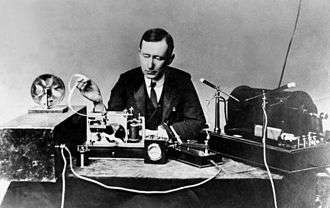
By 1897, Guglielmo Marconi conducted a series of demonstrations with a radio system for signalling for communications over long distances. Marconi is said to have read, while on vacation in 1894, about the experiments that Hertz did in the 1880s. Marconi also read parts of Thomas Commerford Martin's book about the inventions of Nikola Tesla and Scientific American.[54] It was at this time that Marconi began to understand that radio waves could be used for wireless communications.[55] Marconi's early apparatus was a development of Hertz’s laboratory apparatus into a system designed for communications purposes. At first, Marconi used a transmitter to ring a bell in a receiver in his attic laboratory. He then moved his experiments out-of-doors on the family estate near Bologna, Italy, to communicate farther. He replaced Hertz’s vertical dipole with a vertical wire topped by a metal sheet, with an opposing terminal connected to the ground. On the receiver side, Marconi replaced the spark gap with a metal powder coherer, a detector developed by Edouard Branly and other experimenters. Marconi transmitted radio signals for about a mile at the end of 1895.[56]
By 1896, Marconi introduced to the public a device in London and he filed a patent on his earliest system with the British Patent Office on June 2, 1896. In 1897, Marconi was awarded a patent for radio with British patent No. 12,039,[57] Improvements in Transmitting Electrical Impulses and Signals and in Apparatus There-for. The complete specification was filed March 2, 1897. This was Marconi's initial patent for the radio, though it used various earlier techniques of various other experimenters (primarily Tesla) and resembled the instrument demonstrated by others (including Popov). During this time, spark-gap wireless telegraphy was widely researched. In July 1896, Marconi got his invention and new method of telegraphy to the attention of Preece, then engineer-in-chief to the British Government Telegraph Service, who had for the previous twelve years interested himself in the development of wireless telegraphy by the inductive-conductive method. On June 4, 1897, Preece delivered his lecture, "Signalling through Space without Wires".[58][59] Preece devoted considerable time to exhibiting and explaining the Marconi apparatus at the Royal Institution in London, stating that Marconi had invented a new relay which had high sensitivity and delicacy.[60]
In 1896, Jagdish Chandra Bose went to London on a lecture tour and met Marconi, who was conducting wireless experiments for the British post office. In 1897, Marconi founded the Marconi Company Ltd.. Also in 1897, Marconi established the radio station at Niton, Isle of Wight, England. Marconi's wireless telegraphy was inspected by the Post Office telegraph authorities; they made a series of experiments with Marconi's system in the Bristol Channel. In October 1897, wireless signals were sent from Salisbury Plain to Bath, a distance of 34 miles.[61] Marconi's reputation is largely based on the formulation of Marconi's law (1897), and other accomplishments in radio communications and commercializing a practical system.
.jpg)
Other experimental stations were established at Lavernock Point, near Penarth; on Flat Holm, off Cardiff in the Bristol Channel, and at Brean Down, a promontory on the Somerset side. Signals were obtained between the first and last-named points, a distance of approximately eight miles.[62] The receiving instrument used was a Morse inkwriter[63][64] of the Post Office pattern.[65][66]
In a famous 1910 murder case, the culprit (Dr. Hawley Harvey Crippen) was apprehended with the assistance of a transatlantic message sent by wireless telegraphy.
Period 1898–1902
The term wireless telegraphy came into widespread use around the turn of the 19th century, when spark-gap transmitters and primitive receivers made it practical to send telegraph messages over great distances, enabling transcontinental and ship-to-shore signalling. Before that time, wireless telegraphy was an obscure experimental term that applied collectively to an assortment of sometimes unrelated signalling schemes. In 1898, Tesla demonstrated a radio-controlled boat in Madison Square Garden that allowed secure communication[67][68] between transmitter and receiver.[69]
In 1899, Landell de Moura transmitted the human voice from the College of the Sisters of St. Joseph,[70] high in the district of Santana, Brazil, north of the capital city. He also publicly demonstrated his invention on June 3, 1900. As the Jornal do Commercio[71] reported (June 10, 1900), "Last Sunday, on top of Santana in São Paulo, Padre Landell de Moura has particular experience with various devices of his invention. In order to demonstrate some laws which he discovered in studying the propagation of sound, the light and electricity through space, which were crowned with brilliant success." The experiments were performed in the presence of the English Vice Consul S. Paul, Percy Parmenter, Charles Lupton, and other persons of high social position. Upon observing the experiments, Rodriguez Botet, giving news of the trials, said he was not far from the moment of consecrating Landell de Moura as an author of radio discoveries. Landell de Moura later received several patents on wireless technology.[72][73] He would later obtain U.S. Patent 775,337 for a wireless telephone.
In 1898, Marconi opened a radio factory in Hall Street, Chelmsford, England, employing around 50 people. In 1899, Marconi announced his invention of the "iron-mercury-iron coherer with telephone detector" in a paper presented at the Royal Society, London. In May, 1898, communication was established for Lloyd's of London between Ballycastle and the lighthouse on Rathlin Island in the North of Ireland.[74] In July, 1898, the Marconi telegraph was employed to report the results of yacht races at the Kingston Regatta for the Dublin Express newspaper. One set of instruments was set up in a room at Kingstown, and another on board a steamer, the Flying Huntress. The aerial conductor on shore was a strip of wire netting attached to a mast 40 feet high. Several hundred messages were sent and correctly received during the progress of the races.[75]
At this time King Edward VII, then Prince of Wales, had the misfortune to injure his knee and was confined on board the royal yacht Osborne in Cowes Bay.[76] Marconi fitted up his apparatus on board the royal yacht by request, and also at Osborne House, Isle of Wight, and kept up wireless communication for three weeks between these stations.[77] The distances covered were small; but as the yacht moved about, on some occasions high hills were interposed, so that the aerial wires were overtopped by hundreds of feet, yet this was no obstacle to communication. These demonstrations led the Corporation of Trinity House to afford an opportunity for testing the system in practice between the South Foreland Lighthouse, near Dover, and the East Goodwin Lightship, on the Goodwin Sands. This installation was set in operation on December 24, 1898, and proved to be of value. It was shown that when once the apparatus was set up, it could be worked by ordinary seamen with very little training.
At the end of 1898 electric wave telegraphy established by Marconi had demonstrated its utility, especially for communication between ship and ship and ship and shore.[78] The Haven Hotel station[79] and Wireless Telegraph Mast was where much of Marconi's research work on wireless telegraphy was carried out after 1898.[80] In 1899, W. H. Preece delivered a lecture on "Aetheric Telegraphy", stating that the experimental stage in wireless telegraphy had been passed in 1894 and inventors were then entering the commercial stage.[81] Preece, continuing in the lecture, detailed the work of Marconi and other British inventors. The Marconi Company was renamed the Wireless Telegraph Trading Signal Company in 1900. In 1899 he transmitted messages across the English Channel. The British Navy experiments with Marconi's system in the Anglo-Boer War from 1899-1902 were the first use of operational wireless telegraphy in the field.[82]
In 1901, Marconi claimed to have received daytime transatlantic radio frequency signals at a wavelength of 366 metres (820 kHz).[84][85][86] Marconi established a wireless transmitting station at Marconi House, Rosslare Strand, Co. Wexford in 1901 to act as a link between Poldhu in Cornwall and Clifden in Co. Galway. His announcement on 12 December 1901 stated that signals transmitted by the company's new high-power station at Poldhu, Cornwall were received at Signal Hill in St John's, Newfoundland (now part of Canada), using a 152.4-metre (500 ft) kite-supported antenna for reception. The message received was the Morse letter 'S' - three dots. This has recently been contested, however, based on theoretical work as well as a reenactment of the experiment; it is possible that Marconi heard only random atmospheric noise, which was mistaken for a signal, or that he heard a shortwave harmonic of the signal.[85][86] The distance between the two points was about 3,500 kilometres (2,200 mi).[87]
Marconi transmitted from England to Canada and the United States.[88] In 1902, a Marconi station was established in the village of Crookhaven, County Cork, Ireland to provide marine radio communications to ships arriving from the Americas. A ship's master could contact shipping line agents ashore to enquire which port was to receive their cargo without the need to come ashore at what was the first port of landfall.[89] Ireland was also, due to its western location, to play a key role in early efforts to send trans-Atlantic messages. Marconi transmitted from his station in Glace Bay, Nova Scotia, Canada across the Atlantic, and on 18 January 1903 a Marconi station[90] sent a message of greetings from Theodore Roosevelt, the President of the United States, to the King of the United Kingdom, marking the first transatlantic radio transmission originating in the United States.
Period after 1902
In the early 20th century Jozef Murgas, the "Radio Priest",[91] conducted a great deal of revolutionary work in wireless telegraphy. He established a laboratory in Wilkes-Barre, in which he primarily investigated radiotelegraphy. His article in the Tovaryšstvo magazine of 1900 shows that his radiotelegraphy studies had achieved a high level. In 1904, he received his first two US patents: the Apparatus for wireless telegraphy and The way of transmitted messages by wireless telegraphy. Another 11 patents followed between 1907 and 1911. Based on the first two patents, he created the Universal Ether Telegraph Co., which organized a public test of Murgaš's transmitting and receiving facilities in September 1905. The test was successful, but a storm destroyed the antenna masts three months later, which led to the dissolution of the company.
In 1906, Lee De Forest brought out a vacuum tube device which he called the "audion". This was a very sensitive detector of electric oscillations. It consisted of three electrodes in a vacuum tube; one of the electrodes could be heated to incandescence with the result that it emitted electrons (the Edison effect).
American physicist Theodore Case, while studying at Yale University, became interested in using modulated light as a means to transmit and record speech. In 1914, he opened the Case Research Lab to experiment with the photo-electric properties of various materials, leading to the development of the Thallofide (short for thallium oxysulfide), a light-sensitive vacuum tube. The Thallofide tube was originally used by the United States Navy in a top secret ship-to-ship infrared signaling system developed at Case's lab with his assistant Earl Sponable. Case and Sponable's system was first tested off the shores of New Jersey in 1917, and attending the test was Thomas Edison, contracted by the Navy to evaluate new technologies. The test was a success, and the U.S. Navy used the system during and after World War I. This technology, in conjunction with de Forest's Audion, was adapted after the war, as a means to record and play back optical sound in motion pictures.[92] Another inventor, Charles A. Hoxie, invented a similar device, the Pallophotophone, that also became a speech recorder, used by General Electric to record President Calvin Coolidge in 1921 for radio broadcasts.
When the United States entered World War I, private radiotelegraphy stations were prohibited, which put an end to several pioneers' work in this field. By the 1920s, there was a worldwide network of commercial and government radiotelegraphic stations, plus extensive use of radiotelegraphy by ships for both commercial purposes and passenger messages. The ultimate implementation of wireless telegraphy was telex, using radio signals, which was developed in the 1930s and was for many years the only reliable form of communication between many distant countries. The most advanced standard, CCITT R.44, automated both routing and encoding of messages by short wave transmissions. (See telegraphy for more information).
Gallery
-

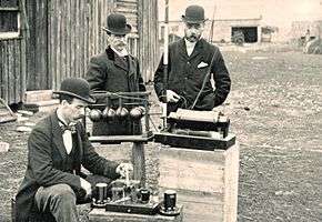
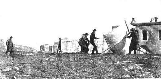
German troops erecting a wireless field telegraph station during World War I
-

German officers and troops manning a wireless field telegraph station during World War I
See also
- AT&T Corporation originally American Telephone and Telegraph Company
- Electrical telegraph
- Imperial Wireless Chain
References and notes
- General
- American Institute of Electrical Engineers. (1908). "Wireless Telephony — By R. A. Fessenden (Illustrated.)", Transactions of the American Institute of Electrical Engineers. New York: American Institute of Electrical Engineers.
- Citations
- ↑ Maver, William Jr. (1903). American Telegraphy and Encyclopedia of the Telegraph: Systems, Apparatus, Operation. New York: Maver Publishing Co. p. 333.
- ↑ Steuart, William Mott; et al. (1906). Special Reports: Telephones and Telegraphs 1902. Washington D.C.: U.S. Bureau of the Census. pp. 118–119.
- ↑ earlyradiohistory.us, UNITED STATES EARLY RADIO HISTORY THOMAS H. WHITE, s e c t i o n 22, Word Origins-Radio
- ↑ Morse code training moving to Goodfellow
- ↑ Coast Station KSM
- ↑ TITLE 47—Telecommunication CHAPTER I—FEDERAL COMMUNICATIONS COMMISSION SUBCHAPTER A—GENERAL PART 13—COMMERCIAL RADIO OPERATORS
- ↑ Fahie, J. J., A History of Wireless Telegraphy, 1838-1899, 1899, p. 29.
- ↑ (U.S. Patent 465,971, Means for Transmitting Signals Electrically, US 465971 A, 1891
- ↑ "Defied the storm's worst-communication always kept up by 'train telegraphy,'" New York Times, March 17, 1888, page 8. Proquest Historical Newspapers (subscription). Retrieved February 6, 2008.
- ↑ Tapan K. Sarkar, History of wireless. Page 262.
- ↑ Rendiconti, xxxix., p. 14.
- ↑ Nature, Volume 75, edited by Sir Norman Lockyer. Page 158.
- 1 2 Bulletin By Société française des électriciens, Société internationale des électriciens. Pg 19-20
- ↑ Rendicontidel R. Ist. Lomb, di te, e lett., Series II, Vol. XLIV. 1911.
- ↑ Hertz, H. (1893). Electric waves: Being researches on the propagation of electric action with finite velocity through space. Dover Publications.
- ↑ Massie, W. W., & Underhill, C. R. (1911). Wireless telegraphy and telephony popularly explained. New York: D. Van Nostrand.
- ↑ Transactions, Volume 27, Part 1 By American Institute of Electrical Engineers.
- 1 2 Electric waves; being research on the propagation of electric action with finite velocity through space by Heinrich Rudolph Hertz, Daniel Evan Jones 1 Review Macmillan and co., 1893. Pages1 - 5.
- ↑ "Hertzian Waves (1901)". Retrieved 2008-08-11.
- ↑ "Hertz wave". Tfcbooks.com. Retrieved 2010-01-31.
- 1 2 Eugenii Katz, "Heinrich Rudolf Hertz". Biographies of Famous Electrochemists and Physicists Contributed to Understanding of Electricity, Biosensors & Bioelectronics.
- ↑ Variations of Conductivity under Electrical Influences, By Edouard Branly. Minutes of proceedings of the Institution of Civil Engineers, Volume 103 By Institution of Civil Engineers (Great Britain) Page 481 (Contained in, Comptes rendus de I'Acade'mie des Sciences, Paris, vol. cii., 1890, p. 78.)
- ↑ On the Changes in Resistance of Bodies under Different Electrical Conditions. By E. Branly. Minutes of proceedings, Volume 104 By Institution of Civil Engineers (Great Britain). 1891. Page 416 (Contained in, Comptes Rendus de l'Academie des Sciences, Paris, 1891, vol. exit., p. 90.)
- ↑ Experiments on the conductivity of insulating bodies, By M. Edouard Branly, M.D. Philosophical magazine. Taylor & Francis., 1892. Page 530 (Contained in, Comples Rendus de l' Academic des Sciences, 24 November 1890 and 12 January 1891, also, Bulletin de la Societi internationals d'electriciens, no. 78, May 1891)
- ↑ Increase of Resistance of Radio-conductors. E. Branly. (Comptes Rendus, 130. pp. 1068-1071, April 17, 1900.)
- ↑ "Wireless Telegraphy". Modern Engineering Practice. VII. American School of Correspondence. 1903. p. 10.
- ↑ although Dr. Branly himself termed it a radio-conductor.
- ↑ Maver's wireless telegraphy: theory and practice By William Maver (jr.)
- ↑ United States Naval Institute (1902). Proceedings: Volume 28, Part 2. Page 443.
- ↑ Branly's filings used, were iron, aluminium, antimony, cadmium, bismuth, &c
- 1 2 3 Minutes of proceedings, Volume 104 By Institution of Civil Engineers (Great Britain)
- ↑ Before closing the circuit a test is made to see that the current at make and break gives the same deviation on the galvanometer. The filings are then placed in the secondary circuit, and the primary opened and closed at regular intervals
- ↑ These deviations were obtained with an induction coil without core. The results obtained with a core were almost identical.
- ↑ A circuit was used consisting of a battery, the body to be tested, and a galvanometer; the electromotive force of the battery used was 1 volt at first, then 100 volts, and then again 1 volt.
- ↑ Text-book on wireless telegraphy, Volume 1 By Rupert Stanley. Pg 299.
- ↑ Collegio Pio-Latino-Americano Pontificio
- ↑ Dias, A., & Raposo, L. (1907). The Brazil of to-day: A book of commercial, political and geographical information on Brazil; impressions of voyage, descriptive and picturesque data about the principal cities, prominent men and leading events of our days, with illustrations and statistics. Nivelles: Lanneau & Despret, printers.
- ↑ Arthur Dias, in his book The Brazil of To-day, refers to Landell de Moura, describing, among other things, the following:
[...] as soon as they arrived in São Paulo in 1893, began making preliminary experiments in order to achieve its purpose of conveying the voice of humans to a distance of 8, 10 or 12 miles, without wires.
- ↑ James O'Neill, Prodigal Genius: The Life of Nikola Tesla, page 86
- ↑ Marc Seifer, Wizard: The Life and Times of Nikola Tesla - page 1721
- 1 2 W. Bernard Carlson, Tesla: Inventor of the Electrical Age, page 127
- ↑ Margaret Cheney, Robert Uth, Jim Glenn, Tesla, Master of Lightning, page 66
- ↑ "Nikola Tesla". ieeeghn.org
- ↑ U.S. Patent 447,921, Tesla, Nikola, "Alternating Electric Current Generator".
- ↑ Radio: Brian Regal, The Life Story of a Technology, page 22
- ↑ note:Experiments with Alternate Currents of High Potential and High Frequency" before the Institution of Electrical Engineers of London where he introduced his high frequency experiments with his "Tesla coil". He repeated this presentation at the Royal Institution and at the Société Française de Physique in Paris. (Tesla: man out of time By Margaret Cheney. page 357)
- ↑ note: at St. Louis, Missouri, Tesla public demonstration called, "On Light and Other High Frequency Phenomena", (Journal of the Franklin Institute, Volume 136 By Persifor Frazer, Franklin Institute (Philadelphia, Pa)
- ↑ Brian Regal, Radio: The Life Story of a Technology, page 22
- ↑ earlyradiohistory.us, Thomas H. White, Nikola Tesla: The Guy Who DIDN'T "Invent Radio", November 1, 2012
- ↑ Sungook Hong, Wireless: From Marconi's Black Box to the Audion, Massachusetts Institute of Technology Press in 2001
- ↑ Bernard Carlson, Tesla: Inventor of the Electrical Age, page 5
- ↑ Brian Regal, Radio: The Life Story of a Technology, page 23
- ↑ Margaret Cheney , Tesla: Man Out of Time, 2011 - pages 203 - 208
- ↑ The Wireless age. (1914). N.Y. [New York] City: Macroni Pub. Corp'n (Wireless Press). "Wireless as a Commercial Fact, From the Inventor's Testimony in the United States Court in Brooklyn. G. Marconi, Part III". Page 75.(cf. "I read parts of a book by Martin, entitled "Inventions, Researches and Writings of Nikola Tesla," published in 1894".)
- ↑ Henry M. Bradford, "Marconi's Three; Transatlantic Radio Stations In Cape Breton". Read before the Royal Nova Scotia Historical Society, 31 January 1996. (ed. the site is reproduced with permission from the Royal Nova Scotia Historical Society Journal, Volume 1, 1998.)
- ↑ Marconi's Three; Transatlantic Radio Stations In Cape Breton.
- ↑ Date of Application 2 June 1896; Complete Specification Left, 2 March 1897; Accepted, 2 July 1897
- ↑ WH Preece, "Signalling through Space without Wires," Proc. Roy. Inst. Lond., 1897, vol. xv. p. 467.
- ↑ Report of the Board of Regents By Smithsonian Institution. Board of Regents, United States National Museum, Smithsonian Institution. 1899. Pg 249+
- ↑ The principles of electric wave telegraphy By Sir John Ambrose Fleming Pg. 429
- ↑ Wireless telegraphy and telephony without wires By Charles Robert Gibson. Pg 79
- ↑ Signals were also exchanged between Lavernock Point and the Flat Holm.
- ↑ Also known as a "Morse Inker".
- ↑ James Erskine-Murray (1907). A handbook of wireless telegraphy: its theory and practice, for the use of electrical engineers, students, and operators. Crosby Lockwood and Son. Page 39
- ↑ Marconi Receiver (Early Form), described from "Electrician" Primer No. 67, had an Aerial Wire, an Earth Wire, a Coherer, a Tapper, Choking Coils, a Dry Cell, a Relay, Battery, Shunts, and a Morse Inkwriter. The coherer consisted of silver electrodes contained in a vacuum tube (4 millimeters), the electrodes being separated by a thin layer composed of nickel and silver filings (nickel, 96 per cent.; silver, 4 per cent.).(The Electrical review, Volume 40. IPC Electrical-Electronic Press, 1897. Page 715.)
- ↑ Marconi's coherer consists of silver electrodes contained in a vacuum tube (4 millimeters), the electrodes being separated by a thin layer composed of nickel and silver filings (nickel, 96 per cent.; silver, 4 per cent). The resistance of this is enormously reduced when electric waves imping upon the tube, and upon the resistance falling, a battery, in circuit with a Morse "inker," is able to work that instrument and record the signals sent out by the transmitter. In series with the Morse "inker" there is an electromagnetic "tapper" which restores the high resistance of the metallic mixture as soon as the signal has been received. Mr. Marconi's transmitter is of the Right pattern; that is to say, an induction coil causes sparks to pass between a succession of hollow metallic spheres, the middle ones of which arc partly immersed in vaseline oil. With a view, it would seem, of increasing the capacity (although the inventor says it is with a view of clearing intervening obstacles and thus obtain a free passage for his waves), he connects electrically to his transmitter either a metallic cone at the top of a pole, 100 feet high, or to a kite. (The Electrical world, Volume 29 Page 822.)
- ↑ Tesla, N., & Anderson, L. I. (1998). Nikola Tesla: guided weapons & computer technology. Tesla presents series, pt. 3. Breckenridge, Colo: Twenty First Century Books.
- ↑ Tesla, N., & Anderson, L. I. (2002). Nikola Tesla on his work with alternating currents and their application to wireless telegraphy, telephony, and transmission of power: an extended interview. Tesla presents series, pt. 1. Breckenridge, Colo: Twenty-First Century Books.
- ↑ The schematics are illustrated in U.S. Patent 613,809 and describes "rotating coherers".
- ↑ Santana High School (Brazil) today
- ↑ Journal of Commerce, a Brazilian economic newspaper (list of newspapers in Brazil)
- ↑ U.S. Patent 771,917 and U.S. Patent 775,337.
- ↑ U.S. Patent 775,846 claims a set of Hertz wave antennae, a source of cathodic waves, and a source of actinic waves, means whereby the changes of a pre-arranged code may be impressed upon one or more sets of the waves, and means to direct them toward a distant station.
- ↑ The distance being 7-5 miles.
- ↑ The distances were from 5 to 20 miles.
- ↑ Earlier, in 1885, a wired telephonic system was established here also. See, The Electrical review, Volume 17. Pg 81
- ↑ The shore mast was 105 feet high, and the wire on board the yacht 83 feet high.
- ↑ A summary of his work on wireless telegraphy up to the beginning of 1899 is given in a paper read by Marconi to the Institution of Electrical Engineers on March 2, 1899. See Journal of the li st. Elee. Eng., 1899, vol. 28, p. 273.
- ↑ Sandbanks, Poole
- ↑ The principles of electric wave telegraphy By Sir John Ambrose Fleming. Page 431-432.
- ↑ Journal of the Society of Arts, Volume 47 By Society of Arts (Great Britain). 1899. Page 519+
- ↑ "Milestones:First Operational Use Of Wireless Telegraphy, 1899-1902". IEEE Global History Network. IEEE. Retrieved 29 July 2011.
- ↑ Wireless telegraphy: its origins, development, inventions, and apparatus By Charles Henry Sewall, pg 144
- ↑ Henry M. Bradford, "Marconi in Newfoundland: The 1901 Transatlantic Radio Experiment"
- 1 2 Henry M. Bradford, Did Marconi Receive Transatlantic Radio Signals in 1901? - Part 1. Wolfville, N.S.
- 1 2 Henry M. Bradford, Did Marconi Receive Transatlantic Radio Signals in 1901? Part 2, Conclusion: The Trans-Atlantic Experiments. Wolfville, N.S.
- ↑ Heralded as a great scientific advance, there was—and continues to be—some skepticism about this claim, partly because the signals had been heard faintly and sporadically.
- ↑ In December, 1902, he established wireless telegraphic communication between Canada (Cape Breton) and England, the first message inaugurating the system being transmitted from the Governor General of Canada to King Edward VII, and a few weeks later a message inaugurating wireless connection between America (Cape Cod, Massachusetts) and Cornwall, England was transmitted from the President of the United States to the British King. (Encyclopaedia of ships and shipping edited by Herbert B. Mason. The Shipping Encyclopaedia, 1908.)
- ↑ "Marconi at Mizen Head Visitor Centre Ireland Visitor Attractions". Mizenhead.net. Retrieved 2012-04-15.
- ↑ built in Wellfleet, Massachusetts in 1901
- ↑ Washburn, D. E. (1980). The peoples of Pennsylvania. Pittsburgh, Pa.: Univ. Center for International Studies. Page 193.
- ↑ Fielding, Raymond (1967). A Technological History of Motion Pictures and Television: An Anthology from the Pages of "The Journal of the Society of Motion Pictures and Television". University of California Press. p. 179. ISBN 0-520-03981-5.
Further reading
Listed by date [latest to earliest]
- Sarkar, T. K., & Baker, D. C. (2006). History of wireless. Hoboken, NJ: Wiley-Interscience.
- Hugh G. J. Aitken, Syntony and Spark: the Origins of Radio, ISBN 0-471-01816-3. 1976.
- Elliot N. Sivowitch, A Technological Survey of Broadcasting’s Pre-History, Journal of Broadcasting, 15:1-20 (Winter 1970-71).
- Colby, F. M., Williams, T., & Wade, H. T. (1930). "Wireless Telegraphy", The New international encyclopaedia. New York: Dodd, Mead and Co.
- "Wireless telegraphy", The Encyclopaedia Britannica. (1922). London: Encyclopædia Britannica.
- Stanley, R. (1919). Text-book on wireless telegraphy. London: Longmans, Green
- Miessner, B. F. (1916). Radiodynamics: The wireless control of torpedoes and other mechanisms. New York: D. Van Nostrand Co
- Thompson, S. P. (1915). Elementary lessons in electricity and magnetism. New York: Macmillan.
- Stanley, R. (1914). Text book on wireless telegraphy. London: Longmans, Green.
- Ashley, C. G., & Hayward, C. B. (1912). Wireless telegraphy and wireless telephony: an understandable presentation of the science of wireless transmission of intelligence. Chicago: American School of Correspondence.
- Massie, W. W., & Underhill, C. R. (1911). Wireless telegraphy and telephony popularly explained. New York: D. Van Nostrand.
- Captain S.S. Robison(1911). Developments in Wireless Telegraphy. International marine engineering, Volume 16. Simmons-Boardman Pub. Co.
- Bottone, S. R. (1910). Wireless telegraphy and Hertzian waves. London: Whittaker & Co.
- Erskine-Murray, J. (1909). A handbook of wireless telegraphy: its theory and practice, for the use of electrical engineers, students, and operators. New York: Van Nostrand.
- Twining, H. L. V., & Dubilier, W. (1909). Wireless telegraphy and high frequency electricity; a manual containing detailed information for the construction of transformers, wireless telegraph and high frequency apparatus, with chapters on their theory and operation. Los Angeles, Cal: The author.
- The New Physics and Its Evolution. Chapter VII: A Chapter in the History of Science: Wireless telegraphy by Lucien Poincaré, eBook #15207, released February 28, 2005. [originally, published: New York, D. Appleton and Company. 1909].
- Fleming, J. A. (1908). The principles of electric wave telegraphy. London: New York and Co.
- Simmons, H. H. (1908). "Wireless telegraphy", Outlines of electrical engineering. London: Cassell and Co.
- Murray, J. E. (1907). A handbook of wireless telegraphy. New York: D. Van Nostrand Co.; [etc.].
- Mazzotto, D., & Bottone, S. R. (1906). Wireless telegraphy and telephony. London: Whittaker & Co.
- Collins, A. F. (1905). Wireless telegraphy; its history, theory and practice. New York: McGraw Pub.
- Sewall, C. H. (1904). Wireless telegraphy: its origins, development, inventions, and apparatus. New York: D. Van Nostrand.
- Trevert, E. (1904). The A.B.C. of wireless telegraphy; a plain treatise on Hertzian wave signaling; embracing theory, methods of operation, and how to build various pieces of the apparatus employed. Lynn, Mass: Bubier Pub.
- Fahie, J. J. (1900). A history of wireless telegraphy, 1838-1899: including some bare-wire proposals for subaqueous telegraphs. Edinburgh: W. Blackwood and Sons.
- Telegraphing across space, Electric wave method. The Electrical engineer. (1884). London: Biggs & Co.
- American Institute of Electrical Engineers. (1884). Transactions of the American Institute of Electrical Engineers. New York: American Institute of Electrical Engineers. (ed., Contains Radio Telephony — By E. B. Craft and E. H. Colpitts (Illustrated). Page 305)
External links
- John Joseph Fahie, A History of Wireless Telegraphy, 1838-1899: including some bare-wire proposals for subaqueous telegraphs, 1899 (first edition).
- John Joseph Fahie, A History of Wireless Telegraphy: including some bare-wire proposals for subaqueous telegraphs, 1901 (second edition).
- John Joseph Fahie, A History of Wireless Telegraphy: including some bare-wire proposals for subaqueous telegraphs, 1901 (second edition, in HTML format).
- Alfred Thomas Story, The Story of Wireless Telegraphy, 1904
- James Bowman Lindsay A short biography on his efforts on electric lamps and telegraphy.
- Sparks Telegraph Key Review
- Principles of Radiotelegraphy (1919)