Wind tunnel
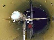

A wind tunnel is a tool used in aerodynamic research to study the effects of air moving past solid objects. A wind tunnel consists of a tubular passage with the object under test mounted in the middle. Air is made to move past the object by a powerful fan system or other means. The test object, often called a wind tunnel model, is instrumented with suitable sensors to measure aerodynamic forces, pressure distribution, or other aerodynamic-related characteristics.
The earliest wind tunnels were invented towards the end of the 19th century, in the early days of aeronautic research, when many attempted to develop successful heavier-than-air flying machines. The wind tunnel was envisioned as a means of reversing the usual paradigm: instead of the air standing still and an object moving at speed through it, the same effect would be obtained if the object stood still and the air moved at speed past it. In that way a stationary observer could study the flying object in action, and could measure the aerodynamic forces being imposed on it.
The development of wind tunnels accompanied the development of the airplane. Large wind tunnels were built during the Second World War. Wind tunnel testing was considered of strategic importance during the Cold War development of supersonic aircraft and missiles.
Later on, wind tunnel study came into its own: the effects of wind on man made structures or objects needed to be studied when buildings became tall enough to present large surfaces to the wind, and the resulting forces had to be resisted by the building's internal structure. Determining such forces was required before building codes could specify the required strength of such buildings and such tests continue to be used for large or unusual buildings.
Still later, wind-tunnel testing was applied to automobiles, not so much to determine aerodynamic forces per se but more to determine ways to reduce the power required to move the vehicle on roadways at a given speed. In these studies, the interaction between the road and the vehicle plays a significant role, and this interaction must be taken into consideration when interpreting the test results. In an actual situation the roadway is moving relative to the vehicle but the air is stationary relative to the roadway, but in the wind tunnel the air is moving relative to the roadway, while the roadway is stationary relative to the test vehicle. Some automotive-test wind tunnels have incorporated moving belts under the test vehicle in an effort to approximate the actual condition, and very similar devices are used in wind tunnel testing of aircraft take-off and landing configurations.
The advances in computational fluid dynamics (CFD) modelling on high speed digital computers has reduced the demand for wind tunnel testing. However, CFD results are still not completely reliable and wind tunnels are used to verify CFD predictions.
Measurement of aerodynamic forces
Air velocity and pressures are measured in several ways in wind tunnels.
Air velocity through the test section is determined by Bernoulli's principle. Measurement of the dynamic pressure, the static pressure, and (for compressible flow only) the temperature rise in the airflow. The direction of airflow around a model can be determined by tufts of yarn attached to the aerodynamic surfaces. The direction of airflow approaching a surface can be visualized by mounting threads in the airflow ahead of and aft of the test model. Smoke or bubbles of liquid can be introduced into the airflow upstream of the test model, and their path around the model can be photographed (see particle image velocimetry).
Aerodynamic forces on the test model are usually measured with beam balances, connected to the test model with beams,strings, or cables.
The pressure distributions across the test model have historically been measured by drilling many small holes along the airflow path, and using multi-tube manometers to measure the pressure at each hole. Pressure distributions can more conveniently be measured by the use of pressure-sensitive paint, in which higher local pressure is indicated by lowered fluorescence of the paint at that point. Pressure distributions can also be conveniently measured by the use of pressure-sensitive pressure belts, a recent development in which multiple ultra-miniaturized pressure sensor modules are integrated into a flexible strip. The strip is attached to the aerodynamic surface with tape, and it sends signals depicting the pressure distribution along its surface.[1]
Pressure distributions on a test model can also be determined by performing a wake survey, in which either a single pitot tube is used to obtain multiple readings downstream of the test model, or a multiple-tube manometer is mounted downstream and all its readings are taken.
The aerodynamic properties of an object can not all remain the same for a scaled model.[2] However, by observing certain similarity rules, a very satisfactory correspondence between the aerodynamic properties of a scaled model and a full-size object can be achieved. The choice of similarity parameters depends on the purpose of the test, but the most important conditions to satisfy are usually:
- Geometric similarity: all dimensions of the object must be proportionally scaled;
- Mach number: the ratio of the airspeed to the speed of sound should be identical for the scaled model and the actual object (having identical Mach number in a wind tunnel and around the actual object is -not- equal to having identical airspeeds)
- Reynolds number: the ratio of inertial forces to viscous forces should be kept. This parameter is difficult to satisfy with a scaled model and has led to development of pressurized and cryogenic wind tunnels in which the viscosity of the working fluid can be greatly changed to compensate for the reduced scale of the model.
In certain particular test cases, other similarity parameters must be satisfied, such as e.g. Froude number.
History
Origins
English military engineer and mathematician Benjamin Robins (1707–1751) invented a whirling arm apparatus to determine drag[3] and did some of the first experiments in aviation theory.
Sir George Cayley (1773–1857) also used a whirling arm to measure the drag and lift of various airfoils.[4] His whirling arm was 5 feet (1.5 m) long and attained top speeds between 10 and 20 feet per second (3 to 6 m/s).
However, the whirling arm does not produce a reliable flow of air impacting the test shape at a normal incidence. Centrifugal forces and the fact that the object is moving in its own wake mean that detailed examination of the airflow is difficult. Francis Herbert Wenham (1824–1908), a Council Member of the Aeronautical Society of Great Britain, addressed these issues by inventing, designing and operating the first enclosed wind tunnel in 1871.[5] Once this breakthrough had been achieved, detailed technical data was rapidly extracted by the use of this tool. Wenham and his colleague John Browning are credited with many fundamental discoveries, including the measurement of l/d ratios, and the revelation of the beneficial effects of a high aspect ratio.
Konstantin Tsiolkovsky built an open-section wind tunnel with a centrifugal blower in 1897, and determined the drag coefficients of flat plates, cylinders and spheres.
Danish inventor Poul la Cour applied wind tunnels in his process of developing and refining the technology of wind turbines in the early 1890s.
Carl Rickard Nyberg used a wind tunnel when designing his Flugan from 1897 and onwards.
In a classic set of experiments, the Englishman Osborne Reynolds (1842–1912) of the University of Manchester demonstrated that the airflow pattern over a scale model would be the same for the full-scale vehicle if a certain flow parameter were the same in both cases. This factor, now known as the Reynolds number, is a basic parameter in the description of all fluid-flow situations, including the shapes of flow patterns, the ease of heat transfer, and the onset of turbulence. This comprises the central scientific justification for the use of models in wind tunnels to simulate real-life phenomena. However, there are limitations on conditions in which dynamic similarity is based upon the Reynolds number alone.


The Wright brothers' use of a simple wind tunnel in 1901 to study the effects of airflow over various shapes while developing their Wright Flyer was in some ways revolutionary.[6] It can be seen from the above, however, that they were simply using the accepted technology of the day, though this was not yet a common technology in America.
In France, Gustave Eiffel (1832-1923) built his first open-return wind tunnel in 1909, powered by a 50 kW electric motor, at Champs-de-Mars, near the foot of the tower that bears his name. Between 1909 and 1912 Eiffel ran about 4000 tests in his wind tunnel, and his systematic experimentation set new standards for aeronautical research. In 1912 Eiffel's laboratory was moved to Auteuil, a suburb of Paris, where his wind tunnel with a 2-metre test section is still operational today. Eiffel significantly improved the efficiency of the open-return wind tunnel by enclosing the test section in a chamber, designing a flared inlet with a honeycomb flow straightener and adding a diffuser between the test section and the fan located at the downstream end of the diffuser; this was an arrangement followed by a number of wind tunnels later built; in fact the open-return low speed wind tunnel is often called the Eiffel-type wind tunnel.
Subsequent use of wind tunnels proliferated as the science of aerodynamics and discipline of aeronautical engineering were established and air travel and power were developed.
The US Navy in 1916 built one of the largest wind tunnels in the world at that time at the Washington Navy Yard. The inlet was almost 11 feet (3.4 m) in diameter and the discharge part was 7 feet (2.1 m) in diameter. A 500 hp electric motor drove the paddle type fan blades.[7]
In 1931 the NACA built a 30-foot by 60-foot "full scale" wind tunnel at Langley Research Center in Langley, Virginia. The tunnel was powered by a pair of fans driven by 4000 hp electric motors. The layout was a double-return, closed-loop format and could accommodate many full-size real aircraft as well as scale models. The tunnel was eventually closed and, even though it was declared a historic national landmark in 1995, demolition began in 2010.
Until World War Two, the world's largest wind tunnel was built in 1932-1934 and located in a suburb of Paris, Chalais-Meudon, France. It was designed to test full size aircraft and had six large fans driven by high powered electric motors.[8] The Chalais Meudon wind tunnel was used by ONERA under the name S1Ch until 1976, e.g. in the development of the Caravelle and Concorde airplanes. Today, this wind tunnel is preserved as a national monument.
Ludwig Prandtl was Theodore von Kármán’s teacher at Gottingen University and suggested the construction of a wind tunnel for tests of airships they were designing.[9]:44 The vortex street of turbulence downstream of a cylinder was tested in the tunnel.[9]:63 When he later moved to Aachen University he recalled use of this facility:
- I remembered the wind tunnel in Gottingen was started as a tool for studies of Zeppelin behavior, but that it had proven to be valuable for everything else from determining the direction of smoke from a ship’s stack, to whether a given airplane would fly. Progress at Aachen, I felt, would be virtually impossible without a good wind tunnel.[9]:76
When von Kármán began to consult with Caltech he worked with Clark Millikan and Arthur L. Klein.[9]:124 He objected to their design and insisted on a return flow making the device "independent of the fluctuations of the outside atmosphere". It was completed in 1930 and used for Northrop Alpha testing.[9]:169 In 1939 General Arnold asked what was required to advance the USAF, and von Kármán answered, "The first step is to build the right wind tunnel."[9]:226 On the other hand, after the successes of the Bell X-2 and prospect of more advanced research, he wrote, "I was in favor of constructing such a plane because I have never believed that you can get all the answers out of a wind tunnel."[9]:302,3
World War Two
In 1941 the US constructed one of the largest wind tunnels at that time at Wright Field in Dayton, Ohio. This wind tunnel starts at 45 feet (14 m) and narrows to 20 feet (6.1 m) in diameter. Two 40-foot (12 m) fans were driven by a 40,000 hp electric motor. Large scale aircraft models could be tested at air speeds of 400 mph (640 km/h).[10]
The wind tunnel used by German scientists at Peenemünde prior to and during WWII is an interesting example of the difficulties associated with extending the useful range of large wind tunnels. It used some large natural caves which were increased in size by excavation and then sealed to store large volumes of air which could then be routed through the wind tunnels. This innovative approach allowed lab research in high-speed regimes and greatly accelerated the rate of advance of Germany's aeronautical engineering efforts. By the end of the war, Germany had at least three different supersonic wind tunnels, with one capable of Mach 4.4 (heated) airflows.[11]
A large wind tunnel under construction near Oetztal, Austria would have had two fans directly driven by two 50,000 horsepower hydraulic turbines. The installation was not completed by the end of the war and the dismantled equipment was shipped to Modane, France in 1946 where it was re-erected and is still operated there by the ONERA. With its 8m test section and airspeed up to Mach 1 it is the largest transonic wind tunnel facility in the world.[12]
On June 22, 1942 Curtiss-Wright financed construction of one of the nation's largest subsonic wind tunnels in Buffalo, N.Y. The first concrete for building was poured on June 22, 1942 on a site that eventually would become Calspan, where the largest independently-owned wind tunnel in the United States still operates.[13]
By the end of World War Two, the US had built eight new wind tunnels, including the largest one in the world at Moffett Field near Sunnyvale, California, which was designed to test full size aircraft at speeds of less than 250 mph[14] and a vertical wind tunnel at Wright Field, Ohio, where the wind stream is upwards for the testing of models in spin situations and the concepts and engineering designs for the first primitive helicopters flown in the US.[15]
Post World War Two
.webm.jpg)
Later research into airflows near or above the speed of sound used a related approach. Metal pressure chambers were used to store high-pressure air which was then accelerated through a nozzle designed to provide supersonic flow. The observation or instrumentation chamber ("test section") was then placed at the proper location in the throat or nozzle for the desired airspeed.
In the United States, concern over the lagging of American research facilities compared to those built by the Germans lead to the Unitary Wind Tunnel Plan Act of 1949, which authorized expenditure to construct new wind tunnels at universities and at military sites. Some German war-time wind tunnels were dismantled for shipment to the United States as part of the plan to exploit German technology developments.[16]
For limited applications, Computational fluid dynamics (CFD) can supplement or possibly replace the use of wind tunnels. For example, the experimental rocket plane SpaceShipOne was designed without any use of wind tunnels. However, on one test, flight threads were attached to the surface of the wings, performing a wind tunnel type of test during an actual flight in order to refine the computational model. Where external turbulent flow is present, CFD is not practical due to limitations in present-day computing resources. For example, an area that is still much too complex for the use of CFD is determining the effects of flow on and around structures, bridges, terrain, etc.

The most effective way to simulative external turbulent flow is through the use of a boundary layer wind tunnel.
There are many applications for boundary layer wind tunnel modeling. For example, understanding the impact of wind on high-rise buildings, factories, bridges, etc. can help building designers construct a structure that stands up to wind effects in the most efficient manner possible. Another significant application for boundary layer wind tunnel modeling is for understanding exhaust gas dispersion patterns for hospitals, laboratories, and other emitting sources. Other examples of boundary layer wind tunnel applications are assessments of pedestrian comfort and snow drifting. Wind tunnel modeling is accepted as a method for aiding in Green building design. For instance, the use of boundary layer wind tunnel modeling can be used as a credit for Leadership in Energy and Environmental Design (LEED) certification through the U.S. Green Building Council.
Wind tunnel tests in a boundary layer wind tunnel allow for the natural drag of the Earth's surface to be simulated. For accuracy, it is important to simulate the mean wind speed profile and turbulence effects within the atmospheric boundary layer. Most codes and standards recognize that wind tunnel testing can produce reliable information for designers, especially when their projects are in complex terrain or on exposed sites.
In the USA many wind tunnels have been decommissioned in the last 20 years, including some historic facilities. Pressure is brought to bear on remaining wind tunnels due to declining or erratic usage, high electricity costs, and in some cases the high value of the real estate upon which the facility sits. On the other hand, CFD validation still requires wind-tunnel data, and this is likely to be the case for the foreseeable future. Studies have been done and others are under way to assess future military and commercial wind tunnel needs, but the outcome remains uncertain.[17] More recently an increasing use of jet-powered, instrumented unmanned vehicles ["research drones"] have replaced some of the traditional uses of wind tunnels.[18]
How it works

Air is blown or sucked through a duct equipped with a viewing port and instrumentation where models or geometrical shapes are mounted for study. Typically the air is moved through the tunnel using a series of fans. For very large wind tunnels several meters in diameter, a single large fan is not practical, and so instead an array of multiple fans are used in parallel to provide sufficient airflow. Due to the sheer volume and speed of air movement required, the fans may be powered by stationary turbofan engines rather than electric motors.
The airflow created by the fans that is entering the tunnel is itself highly turbulent due to the fan blade motion (when the fan is blowing air into the test section – when it is sucking air out of the test section downstream, the fan-blade turbulence is not a factor), and so is not directly useful for accurate measurements. The air moving through the tunnel needs to be relatively turbulence-free and laminar. To correct this problem, closely spaced vertical and horizontal air vanes are used to smooth out the turbulent airflow before reaching the subject of the testing.
Due to the effects of viscosity, the cross-section of a wind tunnel is typically circular rather than square, because there will be greater flow constriction in the corners of a square tunnel that can make the flow turbulent. A circular tunnel provides a smoother flow.
The inside facing of the tunnel is typically as smooth as possible, to reduce surface drag and turbulence that could impact the accuracy of the testing. Even smooth walls induce some drag into the airflow, and so the object being tested is usually kept near the center of the tunnel, with an empty buffer zone between the object and the tunnel walls. There are correction factors to relate wind tunnel test results to open-air results.
The lighting is usually embedded into the circular walls of the tunnel and shines in through windows. If the light were mounted on the inside surface of the tunnel in a conventional manner, the light bulb would generate turbulence as the air blows around it. Similarly, observation is usually done through transparent portholes into the tunnel. Rather than simply being flat discs, these lighting and observation windows may be curved to match the cross-section of the tunnel and further reduce turbulence around the window.
Various techniques are used to study the actual airflow around the geometry and compare it with theoretical results, which must also take into account the Reynolds number and Mach number for the regime of operation.
Pressure measurements
Pressure across the surfaces of the model can be measured if the model includes pressure taps. This can be useful for pressure-dominated phenomena, but this only accounts for normal forces on the body.
Force and moment measurements
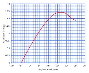
With the model mounted on a force balance, one can measure lift, drag, lateral forces, yaw, roll, and pitching moments over a range of angle of attack. This allows one to produce common curves such as lift coefficient versus angle of attack (shown).
Note that the force balance itself creates drag and potential turbulence that will affect the model and introduce errors into the measurements. The supporting structures are therefore typically smoothly shaped to minimize turbulence.
Flow visualization
Because air is transparent it is difficult to directly observe the air movement itself. Instead, multiple methods of both quantitative and qualitative flow visualization methods have been developed for testing in a wind tunnel.
Qualitative methods
- Smoke
- Tufts
Tufts are applied to a model and remain attached during testing. Tufts can be used to gauge air flow patterns and flow separation.


- Evaporating suspensions
Evaporating suspensions are simply a mixture of some sort or fine powder, talc, or clay mixed into a liquid with a low latent heat of evaporation. When the wind is turned on the liquid quickly evaporates leaving behind the clay in a pattern characteristic of the air flow.

- Oil
When oil is applied to the model surface it can clearly show the transition from laminar to turbulent flow as well as flow separation.

- Fog
Fog (usually from water particles) is created with an ultrasonic piezoelectric nebulizer. The fog is transported inside the wind tunnel (preferably of the closed circuit & closed test section type). An electrically heated grid is inserted before the test section which evaporates the water particles at its vicinity thus forming fog sheets. The fog sheets function as streamlines over the test model when illuminated by a light sheet.

Video of a wind tunnel fog visualization
- Sublimation
If the air movement in the tunnel is sufficiently non-turbulent, a particle stream released into the airflow will not break up as the air moves along, but stay together as a sharp thin line. Multiple particle streams released from a grid of many nozzles can provide a dynamic three-dimensional shape of the airflow around a body. As with the force balance, these injection pipes and nozzles need to be shaped in a manner that minimizes the introduction of turbulent airflow into the airstream.
High-speed turbulence and vortices can be difficult to see directly, but strobe lights and film cameras or high-speed digital cameras can help to capture events that are a blur to the naked eye.
High-speed cameras are also required when the subject of the test is itself moving at high speed, such as an airplane propeller. The camera can capture stop-motion images of how the blade cuts through the particulate streams and how vortices are generated along the trailing edges of the moving blade.
Classification
There are many different kinds of wind tunnels, an overview is given in the list below:
- Low-speed wind tunnel
- High-speed wind tunnel
- Supersonic wind tunnel
- Hypersonic wind tunnel
- Subsonic and transonic wind tunnel
Wind tunnels are also classified based on their main use.
Aeronautical wind tunnels
The main subcategories in the aeronautical wind tunnels are
High Reynolds number tunnels
Reynolds number is one of the governing similarity parameters for the simulation of flow in a wind tunnel. For mach number less than 0.3, it is the primary parameter that governs the flow characteristics. There are three main ways to simulate high Reynolds number, since it is not practical to obtain full scale Reynolds number by use of a full scale vehicle.
- Pressurised tunnels - Here test gases are pressurised to increase the Reynolds number.
- Heavy gas tunnels - Heavier gases like freon and R-134a are used as test gases. The transonic dynamics tunnel at NASA Langley is an example of such a tunnel.
- Cryogenic tunnels - Here test gas is cooled down to increase the Reynolds number. The European transonic wind tunnel uses this technique.
- High-Altitude Tunnels - These are designed to test the effects of shock waves against various aircraft shapes in near vacuum. In 1952 the University of California constructed the first two high-altitude wind tunnels. One for testing objects at 50 to 70 miles above earth and the second one for tests at 80 to 200 miles above earth.[19]
V/STOL tunnels
V/STOL tunnels require large cross section area, but only small velocities. Since power varies with the cube of velocity, the power required for the operation is also less. An example for a V/STOL tunnel is the NASA Langley 14' X 22'tunnel.[20]
Spin tunnels
Aircraft have a tendency to go to spin when they stall. These tunnels are used to study that phenomenon.
Automotive tunnels
Automotive wind tunnels fall into two categories:
- external flow tunnels - Used to study the external flow through the chassis
- climatic tunnels - Used to evaluate the performance of door systems, braking systems etc. under various climatic conditions. Most of the leading automobile manufacturers have their own climatic wind tunnels
Wunibald Kamm "built the first full-scale wind tunnel for motor vehicles."[21]
For external flow tunnels various systems are used to compensate for the effect of the boundary layer on the road surface, including systems of moving belts under each wheel and the body of the car (5 or 7 belt systems) or one large belt under the entire car, or other methods of boundary layer control such as scoops or perforations to suck it away.[22]
Aeroacoustic tunnels
These tunnels are used in the studies of noise generated by flow and its suppression.

Aquadynamic flume
The aerodynamic principles of the wind tunnel work equally on watercraft, except the water is more viscous and so sets greater forces on the object being tested. A looping flume is typically used for underwater aquadynamic testing. The interaction between 2 different types of fluids means that pure windtunnel testing is only partly relevant. However, a similar sort of research is done in a towing tank.
Low-speed oversize liquid testing
Air is not always the best test medium to study small-scale aerodynamic principles, due to the speed of the air flow and airfoil movement. A study of fruit fly wings designed to understand how the wings produce lift was performed using a large tank of mineral oil and wings 100 times larger than actual size, in order to slow down the wing beats and make the vortices generated by the insect wings easier to see and understand.[23]
Fan testing
Wind tunnel tests are also performed to precisely measure the air movement of fans at a specific pressure. By determining the environmental circumstances during measurement, and by revising the air-tightness afterwards, the standardization of the data is ensured.
There are two possible ways of measurement: a complete fan, or an impeller on a hydraulic installation. Two measuring tubes enable measurements of lower air currents (< 30.000 m³/h) as well as higher air currents (< 60.000 m³/h). The determination of the Q/h curve of the fan is one of the main objectives. To determine this curve (and to define other parameters) air technical, mechanical as well as electro technical data are measured:
Air technical:
- Static pressure difference (Pa)
- Amount of moved air (m³/h)
- Average air speed (m/s)
- Specific efficiency (W/1000m³/h)
- Efficiency
Electro technical:
- Tension (V)
- Current (A)
- Cos φ
- Admitted power (W) fan / impeller
- Rotations per minute (RPM)
The measurement can take place on the fan or in the application in which the fan is used.
Wind engineering testing
In Wind Engineering, wind tunnel tests are used to measure the velocity around, and forces or pressures upon structures. Very tall buildings, buildings with unusual or complicated shapes (such as a tall building with a parabolic or a hyperbolic shape), cable suspension bridges or cable stayed bridges are analyzed in specialized atmospheric boundary layer wind tunnels. These feature a long upwind section to accurately represent the wind speed and turbulence profile acting on the structure. Wind tunnel tests provide the necessary design pressure measurements in use of the dynamic analysis and control of tall buildings.[24][25]
See also
- Arsenal (Vienna), climatic wind tunnel centre used by the rail industry
- Automobile design
- Doriot Climatic Chambers, climatic wind tunnel centre operated by the United States military
- Sting (fixture)
- Vertical wind tunnel, a recreational device simulating sky-diving
- Water tunnel, the hydrodynamics-oriented version of a wind tunnel.
- List of Wind Tunnels
References
- ↑ Going with the flow, Aerospace Engineering & Manufacturing, March 2009, pp. 27-28 Society of Automotive Engineers
- ↑ Lissaman, P. B. S. (1 January 1983). "Low-Reynolds-Number Airfoils". 15 (1): 223–239. doi:10.1146/annurev.fl.15.010183.001255 – via Annual Reviews.
- ↑ James Wilson, ed., Mathematical Tracts of the late Benjamin Robins, Esq; … (London, England: J. Nourse, 1761), vol. 1, "An account of the experiments, relating to the resistance of the air, exhibited at different times before the Royal Society, in the year 1746." ; see pp. 202-203.
- ↑ J. A. D. Ackroyd (2011) "Sir George Cayley: The Invention of the Aeroplane near Scarborough at the Time of Trafalgar," Journal of Aeronautical History, 1 : 130–181 ; see pp. 147-149 and 166. Available on-line at: Royal Aeronautical Society
- ↑ Note:
- That Wenham and Browning were attempting to build a wind tunnel is briefly mentioned in: Sixth Annual Report of the Aeronautical Society of Great Britain for the Year 1871, p. 6. From p. 6: "For this purpose [viz, accumulating experimental knowledge about the effects of wind pressure], the Society itself, through Mr. Wenham, had directed a machine to be constructed by Mr. Browning, who, he was sure, would take great interest in the work, and would give to it all the time and attention required."
- In 1872, the wind tunnel was demonstrated to the Aeronautical Society. See: Seventh Annual Report of the Aeronautical Society of Great Britain for the Year 1872, pp. 6-12.
- ↑ Dodson, MG (2005). "An Historical and Applied Aerodynamic Study of the Wright Brothers' Wind Tunnel Test Program and Application to Successful Manned Flight". US Naval Academy Technical Report. USNA-334. Retrieved 2009-03-11.
- ↑ "US Navy Experimental Wind Tunnel" Aerial Age Weekly, 17 January 1916, pages 426-427
- ↑ "Man Made Hurricane Tests Full Size Planes" Popular Mechanics, January 1936, pp.94-95
- 1 2 3 4 5 6 7 Theodore von Kármán (1967) The Wind and Beyond
- ↑ "400mph Wind Tests Planes" Popular Mechanics, July 1941
- ↑ "Video Player > Test Pilot discussion". Space.co.uk. Retrieved 2011-06-28.
- ↑ Ernst Heinrich Hirschel, Horst Prem, Gero Madelung, Aeronautical Research in Germany: From Lilienthal Until Today Springer, 2004 ISBN 354040645X, page 87
- ↑ "Calspan History > Wind Tunnel Construction". calspan.com. Retrieved 2015-04-23.
- ↑ "Wind at Work For Tomorrow's Planes." Popular Science, July 1946, pp. 66-72.
- ↑ "Vertical Wind Tunnel." Popular Science, February 1945, p. 73.
- ↑ HIEBERT, DAVID M. (2002). "PUBLIC LAW 81-415: THE UNITARY WIND TUNNEL PLAN ACT OF 1949 AND THE AIR ENGINEERING DEVELOPMENT CENTER ACT OF 19491" (PDF). Retrieved 2014-04-03.
- ↑ Goldstein, E., "Wind Tunnels, Don't Count Them Out," Aerospace America, Vol. 48 #4, April 2010, pp. 38-43
- ↑ Benjamin Gal-Or, "Vectored Propulsion, Supermaneuverability & Robot Aircraft", Springer Verlag, 1990, ISBN 0-387-97161-0, ISBN 3-540-97161-0
- ↑ "Windless Wind Tunnels for High Altitude Tests." Popular Mechanics, February 1952, p. 105.
- ↑ 14'x22' Subsonic Wind Tunnel. Aeronautics.nasa.gov (2008-04-18). Retrieved on 2014-06-16.
- ↑ "History (1930-1945)". Forschungsinstitut für Kraftfahrwesen und Fahrzeugmotoren Stuttgart. Retrieved 3 September 2010.
- ↑ http://www.dnw.aero/skills-and-specialities/simulation-techniques/ground-simulation.aspx
- ↑ "''Popular Science, Dec 2002''". Carlzimmer.com. Retrieved 2011-06-28.
- ↑ ALY, Aly Mousaad; Alberto Zasso; Ferruccio Resta (2011). "Dynamics and Control of High-Rise Buildings under Multidirectional Wind Loads". Smart Materials Research.
- ↑ ALY, Aly Mousaad; Alberto Zasso; Ferruccio Resta (2011). "On the dynamics of a very slender building under winds: response reduction using MR dampers with lever mechanism". The Structural Design of Tall and Special Buildings. doi:10.1002/tal.647.
- Jewel B. Barlow, William H. Rae, Jr., Allan Pope: "Low speed wind tunnels testing" (3rd ed.) ISBN 978-0-471-55774-6
External ink
![]() Media related to Wind tunnels at Wikimedia Commons
Media related to Wind tunnels at Wikimedia Commons