Weir
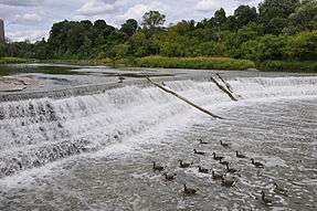

A weir /ˈwɪər/ is a barrier across a river designed to alter the flow characteristics. In most cases weirs take the form of a horizontal barrier across the width of a river that pools water behind it whilst still allowing it to flow steadily over the top. Weirs are commonly used to prevent flooding, measure discharge and help render rivers navigable. In some places the crest of an overflow spillway on a large dam may also be called a weir.
Function
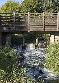
There is not a set definition as to what constitutes a 'weir' and they are normally defined by their purpose. Weirs can vary in size both horizontally and vertically, with the smallest being only a few inches in height whilst the largest may be hundreds of metres long and many metres tall. Unlike a dam, which specifically impounds water, a weir's purpose can be less obvious. They most commonly exist to alter or control river flow characteristics. A particular distinction between dams and weirs is that water flows over the top (crest) of a weir at least some of its length. Common weir types and purposes are outlined below.
Flow measurement
Weirs allow hydrologists and engineers a simple method of measuring the volumetric flow rate in small to medium-sized streams or in industrial discharge locations. Since the geometry of the top of the weir is known and all water flows over the weir, the depth of water behind the weir can be converted to a rate of flow. The calculation relies on the fact that fluid passes through the critical depth of the flow regime in the vicinity of the crest of the weir. If water is not carried away from the weir, it can make flow measurement complicated or even impossible.
The discharge can be summarised as:

Where
- Q is flow rate of fluid
- C is a constant for structure
- L is the width of the crest
- H is the height of head of water over the crest
- n varies with structure (e.g., 3/2 for horizontal weir, 5/2 for v-notch weir)
When used for flow measurement, the weir crest must be free of rust or nicks. Roughness of any form makes the weir discharge more water than indicated by standard discharge equations or tables. Air must also freely circulate under the nappe, as discharge errors of as much as 25% may occur if the nappe is not adequately ventilated.[1]
Control of Invasive Species
As weirs are a physical barrier they can impede the longitudinal movement of fish up and down a river. This can have a negative effect of fish species that migrate as part of their breeding cycle (e.g., Salmonids), but can also be useful as a method of preventing invasive species moving upstream. Although in most cases not the weirs primary purpose, weirs in the Great Lakes region have helped to prevent invasive Sea Lampreys from colonising further upstream. Weirs in this context may also sometimes be referred to as 'low-head dams'.
Watermills
Mill ponds are created by a weir impounding water that then flows over the structure. The energy created by the change in height of the water can then be used to power waterwheels and power mill and other equipment.
Flood Control & Altering River Conditions
Weirs are commonly used to control the flow rates of rivers during periods of high discharge. Sluice gates (or in some cases the height of the weir crest) can be altered to increase or decrease the volume of water flowing downstream. Weirs of this purpose are commonly found upstream of towns and villages and can either be automated or manually operated. By slowing the rate at which water moves downstream even slightly a disproportionate effect can be had on the likelihood of flooding. On larger rivers a weir can also alter the flow characteristics of a river to the point that vessels are able to navigate areas previously inaccessible.
Drawbacks

- Because a weir typically increases oxygen content of the water as it passes over the crest, a weir can harm the local ecology of a river system. A weir artificially reduces the upstream water velocity, which can increase siltation (deposition of fine particles of silt and clay on the river bottom).
- Weirs can have a significant effect on fish migration. Any weir that exceeds either the maximum vertical height a species can jump or creates flow conditions that cannot be bypassed (e.g., due to excessive water velocity) effectively limits the maximum point upstream that fish can migrate. In some cases this can mean that huge lengths of breeding habitat are lost and over time this can have a significant impact of fish populations. In many countries it is now a requirement by law to build fish ladders into the design of a weir that ensures that fish can bypass the barrier.
- Even though the water around weirs can often appear relatively calm, they can be extremely dangerous places to boat, swim, or wade, as the circulation patterns on the downstream side—typically called a hydraulic jump— can submerge a person indefinitely. This phenomenon is so well known to canoeists, kayakers, and others who spend time on rivers that they even have a rueful name for weirs: "drowning machines".[2][3]
Types


There are many different types of weirs. A weir can vary from a simple stone structure that is barely noticeable, to elaborate and very large structures that require extensive management and maintenance.
Labyrinth weir
A labyrinth weir uses a trapezoidal-shaped weir wall geometry (plan view) to increase the weir length. They are versatile structures and can be modified to fit many applications.[4]
Broad-crested weir
A broad-crested weir is a flat-crested structure, with a long crest compared to the flow thickness.[5] When the crest is "broad", the streamlines become parallel to the crest invert and the pressure distribution above the crest is hydrostatic. The hydraulic characteristics of broad-crested weirs were studied during the 19th and 20th centuries. Practical experience showed that the weir overflow is affected by the upstream flow conditions and the weir.
Sharp crested weir (fayoum weir)
A sharp-crested weir allows the water to fall cleanly away from the weir. Sharp crested weirs are typically 1⁄4 inch (6.4 mm) or thinner metal plates. Sharp crested weirs come in many different shapes and styles, such as rectangular (with and without end contractions), V-notch and Cipoletti weirs. Under controlled conditions, sharp crested weirs can exhibit accuracies as good as +/-2%, although under field conditions accuracies greater than +/-5% should not be expected.[6]
The crest of a sharp crested weir should be no thicker than 1⁄8 inch (3.2 mm) to ensure that the nappe springs clear of the weir's crest. Where the weir plate is thicker than 1⁄8 inch (3.2 mm), the downstream face of the weir must be beveled.[7]
Piano keys weir (PKW)
To reduce the risks related to large flooding EDF (French electricity company) has equipped some of its weirs with crests in shape of piano keys. This design makes possible the evacuation of a large flowrate of excess of water in case of extreme flooding.
Compound weir
Sharp crested weirs can be consolidated into three geometrical groups : a) rectangular weir, b) V or triangular notch, and c) special notches, such as trapezoidal, circular or parabolic weirs. For accurate flow measurement over a wider range of flow rates, a compound weir combines two or more types - typically a V-notch weir with a rectangular weir.[8]
These weirs are a combination of a V-notch weir and a rectangular weir and are available for insertion in pipes from 6 to 15 inches (150 to 380 mm) - with secondary adapters available for larger pipe sizes. The weirs are intended to measure no more than 35% of the pipe's open channel flow capacity.
V-notch weir
The V-notch weir is a triangular channel section, used to measure small discharge values. The upper edge of the section is always above the water level, so the channel is always triangular simplifying calculation of the cross-sectional area. V-notch weirs are preferred for low discharges as the head above the weir crest is more sensitive to changes in flow compared to rectangular weirs, for example, the Rehbock weir. Under laboratory conditions, V-notch weirs typically achieve accuracies of 2% to 5%, while field condition accuracies from 5% to 15% may be expected.[9]
V-notch weirs are sized between 22-1/2° and 120°, with 22-1/2°, 30°, 45°, 60°, 90°, and 120° the common size increments - although free-flow discharge equations can be developed from one universal equation for V-notch weirs from 25° to 120° in size.[10]
Sharp crested weir background
The v notch weir is one type of sharp crested weir for which background information is given in Open Channel Flow Measurement 1. Additional general sharp crested weir information is given in this section and then v notch weir equations are discussed in the next two sections. The diagram at the left shows some parameters and terminology used with a sharp crested weir for open channel flow rate measurement.
The weir crest is the top of the weir. For a v notch weir it is the point of the notch, which is the lowest point of the weir opening. The term nappe is used for the sheet of water flowing over the weir. The equations to meter flow in this article require free flow, which takes place when there is air under the nappe. The drawdown is the decrease in water level going over the weir due to the acceleration of the water. The head over the weir is shown as H in the diagram; the height of the weir crest is shown as P; and the open channel flow rate or discharge is shown as Q.
Fully contracted, 90 degree, V notch weir equation
The equation recommended by the Bureau of Reclamation in their Water Measurement Manual, for use with a fully contracted, 90°, v notch, sharp crested weir with free flow conditions and 0.2 ft < H < 1.25 ft, is:
- Where
- Q is discharge in cfs, and
- H is head over the weir in ft.

The conditions for the v notch weir to be fully contracted are .


V notch weir equation for notch angles other than 90 degrees
For notch angles other than 90°, the Kindsvater-Carter equation, as given below, from the Bureau of Reclamation, Water Measurement Manual, should be used. That equation is:
- Where
- Q and H are as previously defined, including units
- θ is the angle of the v notch
- is the effective discharge coefficient
- k is a head correction factor


The diagram at the left is a graph of as a function of notch angle, θ, and the diagram at the right gives k as a function of θ.
A v notch weir is simply a 'v notch' in a plate that is placed so that it obstructs an open channel flow, causing the water to flow over the v notch. It is used to meter flow of water in the channel, by measuring the head of water over the v notch crest. The v notch weir is especially good for measuring a low flow rate, because the flow area decreases rapidly as the head over the v notch gets small.[11]
Minimum Energy Loss weir
The concept of the Minimum Energy Loss (MEL) structure was developed by Gordon McKay in 1971.[12] The first MEL structure was the Redcliffe storm waterway system, also called Humpybong Creek drainage outfall, completed in 1960 in the Redcliffe Peninsula in Queensland, Australia. It consisted of a MEL weir acting as a streamlined drop inlet followed by a 137 m long culvert discharging into the Pacific Ocean. The weir was designed to prevent beach sand being washed in and choking the culvert, as well as to prevent salt intrusion in Humpybong Creek without afflux (rise in water level on the upstream side of an obstruction). The structure is still in use and passed floods greater than the design flow in several instances without flooding (McKay 1970, Chanson 2007).
The concept of the Minimum Energy Loss (MEL) weir was developed to pass large floods with minimum energy loss and afflux, and nearly-constant total head along the waterway. The flow in the approach channel is contracted through a streamlined chute and the channel width is minimum at the chute toe, just before impinging into the downstream natural channel. The inlet and chute are streamlined to avoid significant form losses and the flow may be critical from the inlet lip to the chute toe at design flow. MEL weirs were designed specifically for situations where the river catchment is characterized by torrential rainfalls and by very small bed slope. The first major MEL weir was the Clermont weir (Qld, Australia 1963), if the small control weir at the entrance of Redcliffe culvert is not counted. The largest, Chinchilla weir (Qld, Australia 1973), is listed as a "large dam" by the International Commission on Large Dams.
See also
References
- Notes
- ↑ Factors affecting weir flow measurement accuracy
- ↑ Michael Robinson, Ph.D. P.E., Robert Houghtalen, Ph.D., P.E. "Dangerous dams". Rhode Island Canoe/Kayak Association. Rhode Island. Archived from the original on 2010-08-12. Retrieved 2011-06-26.
- ↑ Lowhead Dams, Ohio DNR
- ↑ Crookston, Brian Mark, "Labyrinth Weirs" (2010). All Graduate Theses and Dissertations. Paper 802.http://digitalcommons.usu.edu/etd/802
- ↑ Chanson 1999, 2004; Henderson 196;, Sturm 2001
- ↑ "Flow Characteristics for Sharp-Crested / Thin-Plate Weirs". Openchannelflow. Retrieved 2015-03-10.
- ↑ "Weir Plate Materials". Openchannelflow. 2013-05-20. Retrieved 2015-03-10.
- ↑ "Compound Weirs for Wide Ranging Flows". Openchannelflow. 2013-04-19. Retrieved 2015-03-10.
- ↑ / V-notch weir accuracy
- ↑
- ↑ by Atif Siddiqui
- ↑ Chanson, H. (2009). Embankment Overtopping Protections System and Earth Dam Spillways. in "Dams: Impact, Stability and Design", Nova Science Publishers, Hauppauge NY, USA, Ed. W.P. Hayes and M.C. Barnes, Chapter 4, pp. 101-132. ISBN 978-1-60692-618-5.
- Bibliography
- Chanson, H. (2004). "The Hydraulics of Open Channel Flow : An Introduction." Butterworth-Heinemann, Oxford, UK, 2nd edition, 630 pages (ISBN 978 0 7506 5978 9).
- Chanson, H. (2007). Hydraulic Performances of Minimum Energy Loss Culverts in Australia, Journal of Performances of Constructed Facilities, ASCE, Vol. 21, No. 4, pp. 264–272 doi:10.1061/(ASCE)0887-3828(2007)21:4(264).
- Gonzalez, C.A., and Chanson, H. (2007). Experimental Measurements of Velocity and Pressure Distribution on a Large Broad-Crested Weir, Flow Measurement and Instrumentation, 18 3-4: 107-113 doi:10.1016/j.flowmeasinst.2007.05.005.
- Henderson, F.M. (1966). "Open Channel Flow." MacMillan Company, New York, USA.
- McKay, G.R. (1971). "Design of Minimum Energy Culverts." Research Report, Dept of Civil Eng., Univ. of Queensland, Brisbane, Australia, 29 pages & 7 plates.
- Sturm, T.W. (2001). "Open Channel Hydraulics." McGraw Hill, Boston, USA, Water Resources and Environmental Engineering Series, 493 pages.
Sources
- Clemmens, Albert (2010). Water Measurement with Flumes and Weirs. ISBN 978-1887201544.
- Akers, Peter (1978). Weirs and Flumes for Flow Measurement. ISBN 978-0471996378.
External links
| Wikimedia Commons has media related to Weirs. |
| Look up weir in Wiktionary, the free dictionary. |
- Hydraulics of Minimum Energy Loss (MEL) culverts and bridge waterways (Click "proceed" at the UQ-ITS Advisory webapge)