Watt's linkage

Watt's linkage (also known as the parallel linkage) is a type of mechanical linkage invented by James Watt (19 January 1736 – 25 August 1819) in which the central moving point of the linkage is constrained to travel on an approximation to a straight line. It was described in Watt's patent specification of 1784 for the Watt steam engine. It is also used in automobile suspensions, allowing the axle of a vehicle to travel vertically while preventing sideways motion.
Description
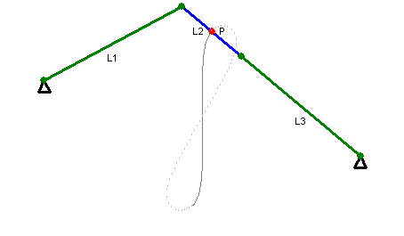
Watt's linkage consists of a chain of three rods, two longer and equal length ones on the outside ends of the chain, connected by a short rod in the middle. The outer endpoints of the long rods are fixed in place relative to each other, and otherwise the three rods are free to pivot around the joints where they meet. Thus, counting the fixed-length connection between the outer endpoints as another bar, Watt's linkage is an example of a four-bar linkage.
History
The idea of its genesis using links is contained in a letter Watt wrote to Matthew Boulton in June 1784.
I have got a glimpse of a method of causing a piston rod to move up and down perpendicularly by only fixing it to a piece of iron upon the beam, without chains or perpendicular guides [...] and one of the most ingenious simple pieces of mechanics I have invented.[2]
This type of linkage is one of several types described in Watt's 28 April 1784 patent specification. However, in his letter to Boulton he was actually describing a development of the linkage which was not included in the patent. The slightly later design, called a parallel motion linkage, led to a more convenient space-saving design which was actually used in his reciprocating (or rotary) beam engines.[3]
The context of Watt's innovation has been described by C. G. Gibson:
- During the Industrial Revolution, mechanisms for converting rotary into linear motion were widely adopted in industrial and mining machinery, locomotives and metering devices. Such devices had to combine engineering simplicity with a high degree of accuracy, and the ability to operate at speed for lengthy periods. For many purposes approximate linear motion is an acceptable substitute for exact linear motion. Perhaps the best known example is the Watt four bar linkage, invented by the Scottish engineer James Watt in 1784.[4]
Shape traced by the linkage
This linkage does not generate a true straight line motion, and indeed Watt did not claim it did so. Rather, it traces out Watt's curve, a lemniscate or figure eight shaped curve; when the lengths of its bars and its base are chosen to form a crossed square, it traces the lemniscate of Bernoulli.[5] In a letter to Boulton on 11 September 1784 Watt describes the linkage as follows.
The convexities of the arches, lying in contrary directions, there is a certain point in the connecting-lever, which has very little sensible variation from a straight line.
Although the Peaucellier–Lipkin linkage, Hart's inversor, and other straight line mechanisms generate true straight-line motion, Watt's linkage has the advantage of much greater simplicity than these other linkages. It is similar in this respect to the Chebyshev linkage, a different linkage that produces approximate straight-line motion; however, in the case of Watt's linkage, the motion is perpendicular to the line between its two endpoints, whereas in the Chebyshev linkage the motion is parallel to this line.
Applications
Double-acting piston
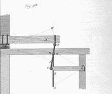
The earlier single-action beam engines used a chain to connect the piston to the beam and this worked satisfactorily for pumping water from mines, etc. However, for rotary motion a linkage that works both in compression and tension provides a better design and allows a double-acting cylinder to be used. Such an engine incorporates a piston acted upon by steam alternately on the two sides, hence doubling its power. The linkage actually used by Watt (also invented by him) in his later rotary beam engines was called the parallel motion linkage, a development of "Watt's linkage", but using the same principle. The piston of the engine is attached to the central point of the linkage, allowing it to act on the two outer beams of the linkage both by pushing and by pulling. The nearly linear motion of the linkage allows this type of engine to use a rigid connection to the piston without causing the piston to bind in its containing cylinder. This configuration also results in a smoother motion of the beam than the single-action engine, making it easier to convert its back-and-forth motion into rotation.[3][6]
An example of Watt's linkage can be found on the high and intermediate pressure piston rod of the 1865 Crossness engines. In these engines, the low pressure piston rod uses the more conventional parallel motion linkage, but the high and intermediate pressure rod does not connect to the end of the beam so there is no requirement to save space.
Automobile suspension
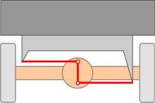

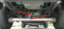
Watt's linkage is used in the rear axle of some car suspensions as an improvement over the Panhard rod, which was designed in the early twentieth century. Both methods intend to prevent relative sideways motion between the axle and body of the car. Watt’s linkage approximates a vertical straight line motion more closely, and does so while locating the centre of the axle rather than toward one side of the vehicle, as more commonly used when fitting a long Panhard rod.[7]
It consists of two horizontal rods of equal length mounted at each side of the chassis. In between these two rods, a short vertical bar is connected. The center of this short vertical rod – the point which is constrained in a straight line motion - is mounted to the center of the axle. All pivoting points are free to rotate in a vertical plane.
In a way, Watt’s linkage can be seen as two Panhard rods mounted opposite each other. In Watt’s arrangement, however, the opposing curved movements introduced by the pivoting Panhard rods largely balance each other in the short vertical rotating bar.
The linkage can be inverted, in which case the centre P is attached to the body, and L1 and L3 mount to the axle. This reduces the unsprung mass and changes the kinematics slightly. This is used on Australian V8 Supercars.
Watt's linkage can also be used to prevent axle movement in the longitudinal direction of the car. This application involves two Watt's linkages on each side of the axle, mounted parallel to the driving direction, but just a single 4-bar linkage is more common in racing suspension systems
References
| Wikimedia Commons has media related to Watt's linkage. |
- ↑ Franz Reuleaux, The Kinematics of Machinery (1876), page 4.
- ↑ As quoted in the 1890 Encyclopædia Britannica, "James Watt", Vol. 24, p. 413.
- 1 2 Ferguson, Eugene S. (1962). "Kinematics of Mechanisms from the Time of Watt". United States National Museum Bulletin. 228: 185–230. Retrieved 12 May 2013.. Also available at https://www.gutenberg.org/files/27106/27106-h/27106-h.htm
- ↑ C. G. Gibson (1998) Elementary Geometry of Algebraic Curves, pp 12, 13, Cambridge University Press ISBN 0-521-64140-3
- ↑ Bryant, John; Sangwin, Christopher J. (2008), How round is your circle? Where Engineering and Mathematics Meet, Princeton University Press, pp. 58–59, ISBN 978-0-691-13118-4.
- ↑ Hills, Richard (2006). James Watt, vol 3: Triumph through Adversity, 1785-1819. LandmarkPublishing Ltd. pp. 34–38.
- ↑ Adams, Herb (1993), Chassis Engineering, Penguin, p. 62, ISBN 978-1-55788-055-0.
External links
- Watt Beam Engine
- How to draw a straight line, by A.B. Kempe, B.A.
- Lemniscoidal (figure 8 curved) linkage of the first kind by Watt
- Lemniscoidal linkage of the second and third kind by Watt
- A simulation using the Molecular Workbench software.