Vortex tube
The vortex tube, also known as the Ranque-Hilsch vortex tube, is a mechanical device that separates a compressed gas into hot and cold streams. The air emerging from the "hot" end can reach temperatures of 200 °C (392 °F), and the air emerging from the "cold end" can reach −50 °C (−58 °F).[1] It has no moving parts.
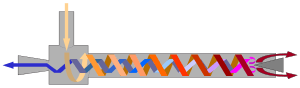
Pressurised gas is injected tangentially into a swirl chamber and accelerated to a high rate of rotation. Due to the conical nozzle at the end of the tube, only the outer shell of the compressed gas is allowed to escape at that end. The remainder of the gas is forced to return in an inner vortex of reduced diameter within the outer vortex.
Method of operation
To explain the temperature separation in a vortex tube, there are two main approaches:
Fundamental approach: the physics
This approach is based on first-principles physics alone and is not limited to vortex tubes only, but applies to moving gas in general. It shows that temperature separation in a moving gas is due only to enthalpy conservation in a moving frame of reference.
The thermal process in the vortex tube can be estimated in the following way: 1) The adiabatic expansion of the incoming gas, which cools the gas and turns its heat energy into the kinetic energy of rotation. The total enthalpy (which is the sum of the enthalpy and the kinetic energy), however, is being conserved. 2) The peripheric rotating gas flow moves towards the hot outlet. Here the heat recuperation effect takes place between the quickly rotating peripheric flow and the opposite slowly rotating axial flow. Here the heat transfers from axial flow to the peripheric one. 3) The kinetic energy of rotation turns into the heat energy by the means of the viscous dissipation. The temperature of the gas rises. As the total enthalpy has been increased during the heat recuperation process, this temperature is higher than the incoming gas. 4) Some of the hot gas leaves the hot outlet, carrying away the excess heat. 5) The rest of the gas turns towards the cold outlet. As it passes its way to the cold outlet, its heat energy is transferred to the peripheric flow. Although the temperature at the axis and at the periphery is about the same everywhere, the rotation is slower at the axis, so the total enthalpy is lower as well. 6) The low total enthalpy cooled gas from the axial flow leaves the cold outlet.
The main physical phenomenon of the vortex tube is the temperature separation between the cold vortex core and the warm vortex periphery. The "vortex tube effect" is fully explained with the work equation of Euler,[2] also known as Euler's turbine equation, which can be written in its most general vectorial form as:[3]
- ,

where is the total, or stagnation temperature of the rotating gas at radial position , the absolute gas velocity as observed from the stationary frame of reference is denoted with ; the angular velocity of the system is and is the isobaric heat capacity of the gas. This equation has been published in 2012; it explains the fundamental operating principle of vortex tubes. The search for this explanation began in 1933 when the vortex tube was discovered and continued for more than 80 years.


The above equation is valid for an adiabatic turbine passage; it clearly shows that while gas moving towards the center is getting colder the peripheral gas in the passage is "getting faster". Therefore, vortex cooling is due to angular propulsion. The more the gas cools by reaching the center, the more rotational energy it delivers to the vortex and thus the vortex rotates even faster. This explanation stems directly from the law of energy conservation. Compressed gas at room temperature is expanded in order to gain speed through a nozzle; it then climbs the centrifugal barrier of rotation during which energy is also lost. The lost energy is delivered to the vortex, which speeds its rotation. In a vortex tube, the cylindrical surrounding wall confines the flow at periphery and thus forces conversion of kinetic into internal energy, which produces hot air at the hot exit.
Therefore, the vortex tube is a rotorless turboexpander.[4] It consists of a rotorless radial inflow turbine (cold end, center) and a rotorless centrifugal compressor (hot end, periphery). The work output of the turbine is converted into heat by the compressor at the hot end.
Phenomenological approach
This approach relies on observation and experimental data. It is specifically tailored to the geometrical shape of the vortex tube and the details of its flow and is designed to match the particular observables of the complex vortex tube flow, namely turbulence, acoustic phenomena, pressure fields, air velocities and many others. The earlier published models of the vortex tube are phenomenological. They are:
- Radial pressure difference: centrifugal compression and air expansion
- Radial transfer of angular momentum
- Radial acoustic streaming of energy
- Radial heat pumping
More on these models can be found in recent review articles on vortex tubes.[5][6]
The phenomenological models were developed at an earlier time when the turbine equation of Euler was not thoroughly analyzed; in the engineering literature, this equation is studied mostly to show the work output of a turbine; while temperature analysis is not performed since turbine cooling has more limited application unlike power generation, which is the main application of turbines. Phenomenological studies of the vortex tube in the past have been useful in presenting empirical data. However, due to the complexity of the vortex flow this empirical approach was able to show only aspects of the effect but was unable to explain its operating principle. Dedicated to empirical details, for a long time the empirical studies made the vortex tube effect appear enigmatic and its explanation – a matter of debate.
History
The vortex tube was invented in 1931 by French physicist Georges J. Ranque.[7] German physicist Rudolf Hilsch improved the design and published a widely read paper in 1947 on the device, which he called a Wirbelrohr (literally, whirl pipe).[8] The vortex tube was used to separate gas mixtures, oxygen and nitrogen, carbon dioxide and helium, carbon dioxide and air in 1967 by Linderstrom-Lang.[9] [10] Vortex tubes also seem to work with liquids to some extent, as demonstrated by Hsueh and Swenson in a laboratory experiment where free body rotation occurs from the core and a thick boundary layer at the wall. Air is separated causing a cooler air stream coming out the exhaust hoping to chill as a refrigerator.[11] In 1988 R.T.Balmer applied liquid water as the working medium. It was found that when the inlet pressure is high, for instance 20-50 bar, the heat energy separation process exists in incompressible (liquids) vortex flow as well. Note that this separation is only due to heating; there is no longer cooling observed since cooling requires compressibility of the working fluid.
Efficiency
Vortex tubes have lower efficiency than traditional air conditioning equipment.[12] They are commonly used for inexpensive spot cooling, when compressed air is available.
Applications
Current applications
Commercial vortex tubes are designed for industrial applications to produce a temperature drop of up to 71 °C (127 °F). With no moving parts, no electricity, and no Freon, a vortex tube can produce refrigeration up to 6,000 BTU/h (1,800 W) using only filtered compressed air at 100 PSI (6.9 bar). A control valve in the hot air exhaust adjusts temperatures, flows and refrigeration over a wide range.[13]
Vortex tubes are used for cooling of cutting tools (lathes and mills, both manually-operated and CNC machines) during machining. The vortex tube is well-matched to this application: machine shops generally already use compressed air, and a fast jet of cold air provides both cooling and removal of the "chips" produced by the tool. This completely eliminates or drastically reduces the need for liquid coolant, which is messy, expensive, and environmentally hazardous.
See also
References
- ↑ Walker, Jearl (1975). "The madness of stirring tea". The Flying Circus of Physics. John Wiley & Sons, Inc. p. 97. ISBN 0-471-91808-3.
- ↑ - Z.S. Spakovszky. Unified: thermodynamics and propulsion (Lecture notes), Massachusetts Institute of Technology, Cambridge, Mass. 2007. ch. 12.3.
- ↑ Polihronov, J.; et al. "Thermodynamics of angular propulsion in fluids". Physical Review Letters. 109 (5): 054504. Bibcode:2012PhRvL.109e4504P. doi:10.1103/PhysRevLett.109.054504.
- ↑ Polihronov, J.; et al. "Vortex tube effect without walls". Canadian Journal of Physics. 93 (8): 850–854. doi:10.1139/cjp-2014-0227.
- ↑ Xue, Y.; et al. (2010). "A critical review of temperature separation in a vortex tube". Exper. Therm. Fluid Sci. 34 (8): 1367–1374. doi:10.1016/j.expthermflusci.2010.06.010.
- ↑ Eiamsa-ard, S.; et al. (2008). "Review of Ranque–Hilsch effects in vortex tubes". Renewable and Sustainable Energy Reviews. 12 (7): 1822–1842. doi:10.1016/j.rser.2007.03.006.
- ↑ Georges Joseph Ranque, “Method and apparatus for obtaining from a fluid under pressure two currents of fluids at different temperatures,” U.S. Patent no. 1,952,281 (filed: December 6, 1932 ; issued: March 27, 1934).
- ↑ Hilsch, Rudolf (1947). "The use of the expansion of gases in a centrifugal field as cooling process". The Review of Scientific Instruments. 18 (2): 108–113. doi:10.1063/1.1740893. Translated from the original German article: Rudolf Hilsch (1946) "Die Expansion von Gasen im Zentrifugalfeld als Kälteprozeß" (The expansion of gases in a centrifugal field as a cooling process), Zeitschrift für Naturforschung, 1 : 208–214. Available on-line at: Zeitschrift für Naturforschung
- ↑ Chengming Gao, Experimental Study on the Ranque-Hilsch Vortex Tube, (2005) page 2
- ↑ Vortex tubes are constructed of stainless steel and use a generator and valve made of brass and sealed with viton o-rings to allow their use in the widest range of environments.
- ↑ R.T. Balmer. Pressure-driven Ranque-Hilsch temperature separation in liquids. Trans. ASME, J. Fluids Engineering, 110:161–164, June 1988.
- ↑ Polihronov, J.; et al. "The maximum coefficient of performance (COP) of vortex tubes". Canadian Journal of Physics. 93: 1279–1282. doi:10.1139/cjp-2015-0089.
- ↑ Newman Tools Inc. http://www.newmantools.com/vortex.htm
Further reading
- G. Ranque, Expériences sur la Détente Giratoire avec Productions Simultanées d'un Echappement d'air Chaud et d'un Echappement d'air Froid, J. de Physique et Radium 4(7)(1933) 112S.
- H. C. Van Ness, Understanding Thermodynamics, New York: Dover, 1969, starting on page 53. A discussion of the vortex tube in terms of conventional thermodynamics.
- Mark P. Silverman, And Yet it Moves: Strange Systems and Subtle Questions in Physics, Cambridge, 1993, Chapter 6
- Samuel B. Hsueh and Frank R. Swenson,"Vortex Diode Interior Flows," 1970 Missouri Academy of Science Proceedings, Warrensburg, Mo.
- C. L. Stong, The Amateur Scientist, London: Heinemann Educational Books Ltd, 1962, Chapter IX, Section 4, The "Hilsch" Vortex Tube, p514-519.
- Van Deemter, J. J. "On the Theory of the Ranque-Hilsch Cooling Effect". Applied Science Research. 3: 174–196.
- Saidi, M.H.; Valipour, M.S. (2003). "Experimental Modeling of Vortex Tube Refrigerator". J. of Applied Thermal Engineering. 23: 1971–1980. doi:10.1016/s1359-4311(03)00146-7.
- Valipour, MS; Niazi, N (2011). "Experimental modeling of a curved Ranque–Hilsch vortex tube refrigerator". International Journal of Refrigeration. 34 (4): 1109–1116. doi:10.1016/j.ijrefrig.2011.02.013.
- M. Kurosaka, Acoustic Streaming in Swirling Flow and the Ranque-Hilsch (vortex-tube) Effect, Journal of Fluid Mechanics, 1982, 124:139-172
- M. Kurosaka, J.Q. Chu, J.R. Goodman, Ranque-Hilsch Effect Revisited: Temperature Separation Traced to Orderly Spinning Waves or 'Vortex Whistle', Paper AIAA-82-0952 presented at the AIAA/ASME 3rd Joint Thermophysics Conference (June 1982)
- Gao, Chengming. Experimental Study on the Ranque-Hilsch Vortex Tube. Eindhoven : Technische Universiteit Eindhoven. ISBN 90-386-2361-5.
- R. Ricci, A. Secchiaroli, V. D’Alessandro, S. Montelpare. Numerical analysis of compressible turbulent helical flow in a Ranque-Hilsch vortex tube. Computational Methods and Experimental Measurement XIV, pp. 353–364, Ed. C. Brebbia, C.M. Carlomagno, ISBN 978-1-84564-187-0.
- A. Secchiaroli, R. Ricci, S. Montelpare, V. D’Alessandro. Fluid Dynamics Analysis of a Ranque-Hilsch Vortex-Tube. Il Nuovo Cimento C, vol.32, 2009, ISSN 1124-1896.
- A. Secchiaroli, R. Ricci, S. Montelpare, V. D’Alessandro. Numerical simulation of turbulent flow in a Ranque-Hilsch vortex-tube. Int. J. of Heat and Mass Transfer, Vol. 52, Issues 23-24, November 2009, pp. 5496–5511, ISSN 0017-9310.
- N. Pourmahmoud, A. Hassanzadeh, O. Moutaby. Numerical Analysis of The Effect of Helical Nozzles Gap on The Cooling Capacity of Ranque Hilsch Vortex Tube. Int. J. of Refrigeration, Vol. 35, Issue 5, 2012, pp. 1473–1483, ISSN 0140-7007.
- [1] M. G. Ranque, 1933, "Experiences sur la detente giratoire avec production simulanees d’un echappement d’air chaud et d’air froid", Journal de Physique et le Radium (in French), Supplement, Vol. 7, No. 4, pp. 112–114.
- [2] R. Hilsch, 1947, "The Use of the Expansion of Gases in a Centrifugal Field as Cooling Process", The Review of Scientific Instruments, Vol. 18, No. 2, pp. 108–113.
- [3].J Reynolds, 1962, "A Note on Vortex Tube Flows", Journal of Fluid Mechanics, Vol. 14, pp. 18–20.
- [4]. T. T. Cockerill, 1998, "Thermodynamics and Fluid Mechanics of a Ranque-Hilsch Vortex Tube", Ph.D. Thesis, University of Cambridge, Department of Engineering.
- [5] W. Fröhlingsdorf, and H. Unger, 1999, "Numerical Investigations of the Compressible Flow and the Energy Separation in the Ranque-Hilsch Vortex Tube", Int. J. Heat Mass Transfer, Vol. 42, pp. 415–422.
- [6] J. Lewins, and A. Bejan, 1999, "Vortex Tube Optimization Theory", Energy, Vol. 24, pp. 931–943.
- [7] J. P. Hartnett, and E. R. G. Eckert, 1957, "Experimental Study of the Velocity and Temperature Distribution in a high-velocity vortex-type flow", Transactions of the ASME, Vol. 79, No. 4, pp. 751–758.
- [8] M. Kurosaka, 1982, "Acoustic Streaming in Swirling Flows", Journal of Fluid Mechanics, Vol. 124, pp. 139–172.
- [9] K. Stephan, S. Lin, M. Durst, F. Huang, and D. Seher, 1983, "An Investigation of Energy Separation in a Vortex Tube", International Journal of Heat and Mass Transfer, Vol. 26, No. 3, pp. 341–348.
- [10] B. K. Ahlborn, and J. M. Gordon, 2000, "The Vortex Tube as a Classical Thermodynamic Refrigeration Cycle", Journal of Applied Physics, Vol. 88, No. 6, pp. 3645–3653.
- [11] G. W. Sheper, 1951, Refrigeration Engineering, Vol. 59, No. 10, pp. 985–989.
- [12] J. M. Nash, 1991, "Vortex Expansion Devices for High Temperature Cryogenics", Proc. of the 26th Intersociety Energy Conversion Engineering Conference, Vol. 4, pp. 521–525.
- [13] D. Li, J. S. Baek, E. A. Groll, and P. B. Lawless, 2000, "Thermodynamic Analysis of Vortex Tube and Work Output Devices for the Transcritical Carbon Dioxide Cycle", Preliminary Proceedings of the 4th IIR-Gustav Lorentzen Conference on Natural Working Fluids at Purdue, E. A. Groll & D. M. Robinson, editors, Ray W. Herrick Laboratories, Purdue University, pp. 433–440.
- [14] H. Takahama, 1965, "Studies on Vortex Tubes", Bulletin of JSME, Vol. 8, No. 3, pp. 433–440.
- [15] B. Ahlborn, and S. Groves, 1997, "Secondary Flow in a Vortex Tube", Fluid Dyn. Research, Vol. 21, pp. 73–86.
- [16] H. Takahama, and H. Yokosawa, 1981, "Energy Separation in Vortex Tubes with a Divergent Chamber", ASME Journal of Heat Transfer, Vol. 103, pp. 196–203.
- [17] M. Sibulkin, 1962, "Unsteady, Viscous, Circular Flow. Part 3: Application to the Ranque-Hilsch Vortex Tube", Journal of Fluid Mechanics, Vol. 12, pp. 269–293.
- [18] K. Stephan, S. Lin, M. Durst, F. Huang, and D. Seher, 1984, "A Similarity Relation for Energy Separation in a Vortex Tube", Int. J. Heat Mass Transfer, Vol. 27, No. 6, pp. 911–920.
- [19] H. Takahama, and H. Kawamura, 1979, "Performance Characteristics of Energy Separation in a Steam-Operated Vortex Tube", International Journal of Engineering Science, Vol. 17, pp. 735–744.
- [20] G. Lorentzen, 1994, "Revival of Carbon Dioxide as a Refrigerant", H&V Engineer, Vol. 66. No. 721, pp. 9–14.
- [21] D. M. Robinson, and E. A. Groll, 1996, "Using Carbon Dioxide in a Transcritical Vapor Compression Refrigeration Cycle", Proceedings of the 1996 International Refrigeration Conference at Purdue, J. E. Braun and E. A. Groll, editors, Ray W. Herrick Laboratories, Purdue University, pp. 329–336.
- [22] W. A. Little, 1998, "Recent Developments in Joule-Thomson Cooling: Gases, Coolers, and Compressors", Proc. Of the 5th Int. Cryocooler Conference, pp. 3–11.
- [23] A. P. Kleemenko, 1959, "One Flow Cascade Cycle (in schemes of Natural Gas Liquefaction and Separation)", Proceedings of the 10th International Congress on Refrigeration, Pergamon Press, London, p. 34.
- [24] J. Marshall, 1977, "Effect of Operating Conditions, Physical Size, and Fluid Characteristics on the Gas Separation Performance of a Linderstrom-Lang Vortex Tube", Int. J. Heat Mass Transfer, Vol. 20, pp. 227–231
- [25] s.chhimpa ,Dr. vikas bansal "application of vortex tube in refrigeration "
External links
- G. J. Ranque's U.S. Patent
- Detailed explanation of the vortex tube effect with many pictures
- Oberlin college physics demo
- Articles On Vortex Tube