Vibrator (electronic)
In electronics before the development of switch-mode power supplies and the introduction of semiconductor devices operating off low voltage, there was a requirement to generate voltages of about 50 to 250V DC from vehicle batteries. Electromechanical components known as vibrators were used in a circuit similar to modern solid state inverter circuits to provide a pulsating DC which could be converted to a higher voltage with a transformer, rectified, and filtered to create higher-voltage DC. This "vibrator" is essentially a relay using normally closed contacts to supply power to the relay coil, thus immediately breaking the connection, only to be reconnected very quickly through the normally closed contacts. It happens so rapidly it vibrates, and sounds like a buzzer. This same rapidly pulsing contact applies the rising and falling DC voltage to the transformer which can step it up to a higher voltage.[1]
The primary use for this type of circuit was to operate vacuum tube radios in vehicles, but it also saw use with other mobile electronic devices with a 6 or 12V accumulator, especially in places with no mains electricity supply such as farms. These vibrator power supplies became popular in the 1940s, replacing more bulky motor-generator systems for the generation of AC voltages for such applications.[2][3] Vacuum tubes require plate voltages ranging from about 45 volts to 250 volts in electronic devices such as radios. For portable radios, hearing aids and similar equipment, B batteries were manufactured with various voltage ratings. In order to provide the necessary voltage for a radio from the typical 6 or 12 volt DC supply available in a car or from a farm lighting battery, it was necessary to convert the steady DC supply to a pulsating DC and use a transformer to increase the voltage.
Vibrators often experienced mechanical malfunctions, being constantly in motion, such as the springs losing tension, and the contact points wearing down.[3] As tubes began to be replaced by transistor based electrical systems, the need to generate such high voltages began to diminish. Mechanical vibrators fell out of production near the end of the 20th century, but solid-state electronic vibrators are still manufactured to be backwards compatible with older units.[4]
Use
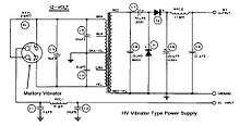
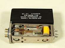
The vibrator was a device with switch contacts on flexible metal strips. When the vibrator was operated the strips vibrated rapidly in such a way as to make contacts presenting a 6 or 12V DC from the battery in alternating sense, rapidly exchanging positive and negative, effectively generating a square wave. Unlike DC, an alternating voltage applied to the terminals of the primary winding of a transformer will induce a different (and often higher) voltage of any desired value at the secondary; this voltage can be rectified by a thermionic diode or copper-oxide or selenium rectifier, or by an additional set of mechanical contacts making the vibrator output a synchronous rectifier. The rectified output is then filtered, ultimately converting a DC voltage to a higher one, with some losses dissipated as heat.
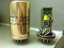
This arrangement is an electromechanical inverter circuit. The vibrator switches used for this purpose wore out after a time, so were usually encased in a steel or aluminum can with a plug for easy replacement when mounted in a socket similar to those used for tubes.
See also
References
- ↑ Bedford, B. D.; Hoft, R. G. (1964). Principles of Inverter Circuits. New York: John Wiley & Sons, Inc. ISBN 0-471-06134-4.
- ↑ Fundamental Principals of Vibrator Power Supply Design (PDF) (First ed.). Indianapolis, Indiana: P. R. Mallory & Co., Inc. March 1947. p. 9.
- 1 2 "Vibrator Power Supplies". www.radioremembered.org. Retrieved 2016-01-24.
- ↑ "Radio Vibrators MikeHaganAntiqueAutoRadio.com". www.mikehaganantiqueautoradio.com. Retrieved 2016-01-24.