Variable pitch fan
The Variable Pitch Fan is a mechanism used to vary the fan pitch similar to that of a variable-pitch propeller. One example is the Turbomeca Astafan turbofan engine. Another is the proposed Rolls-Royce Trent Ultrafan. Variable Pitch Fans are also used in some other applications, such as industrial.
Technology
In a conventional turbofan, usually a single shaft (the "low-pressure" or LP shaft) connects the fan, the intermediate-pressure compressor and the low-pressure turbine, whilst a second concentric shaft (the "high-pressure" or HP shaft) connects the high-pressure compressor and high-pressure turbine. However, in the Rolls-Royce RB211 and Trent engine series, the intermediate-pressure compressor is not connected to the LP shaft but is mounted on a concentric IP shaft, which is driven by the intermediate-pressure (IP) turbine
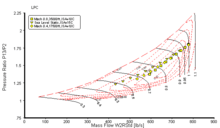
Each compression component (e.g. fan) has a compressor map which (usually) has been generated by comprehensive testing of the unit on a compressor rig. Engineers can superimpose operating lines on these compressor maps to show the locus of operation of the unit in terms of pressure ratio, corrected flow and efficiency. Speed and surge margin can also be inferred.
On a modern civil turbofan engine, the fan is a single stage device, usually developing a pressure ratio of less than 1.9:1 at maximum corrected speed.
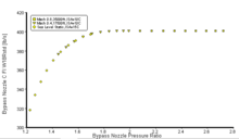
At cruise flight speed (e.g. Mach 0.8), the ram rise in the intake supplements the fan pressure ratio to choke the secondary (i.e. cold) nozzle, so that the cold air in the bypass stream reaches sonic velocity (i.e. Mach 1.0) at the nozzle throat. As the engine is throttled back the reducing cold nozzle pressure ratio is sufficient to still choke the nozzle resulting in a straight, positive slope, operating line on the fan map. At lower engine thrust the cold nozzle may well unchoke causing the operating line to start curving away from the straight choked line. At a lower cruise flight speed (e.g. Mach 0.75) the cold nozzle may well be still choked at full throttle, but will unchoke early as the is engine throttled back.
However, the situation changes at low flight speeds. The ram rise in the intake is negligible, so the cold nozzle pressure ratio is not even as high as the fan pressure ratio because of the bypass duct pressure loss. Consequently, the cold nozzle is likely to be unchoked, resulting in a highly curved operating line, significantly closer to the surge line than the high speed cruise operating line, resulting in a lower fan surge margin particularly at low thrust settings.
At intermediate flight speeds the fan operating lines will be curved and lie somewhere between the low speed and cruise speed operating lines. If a curved low flight speed operating line is extrapolated to higher flow, it tends to coalesce with the straight high flight speed operating line, also extrapolated.
For simplicity, the description given above is for an unmixed turbofan where there are separate primary (i.e. hot) and secondary (i.e. cold) nozzles. However, although it is more complicated to explain, a mixed turbofan (with a single mixed stream nozzle) would behave in much the same way, albeit with slightly steeper operating lines.
The trend with new civil turbofans is towards a lower specific thrust to reduce jet noise and improve specific fuel consumption. A lower specific thrust means that the fan mass flow is higher for a given net thrust. Consequently, the optimum fan pressure ratio tends to reduce, making the cold nozzle even more unchoked, particularly at low flight speeds. This means that, relatively speaking, the low flight speed working lines tend to be higher on the map and even nearer surge.
Incidentally, lower specific thrust turbofans also tend to have a higher bypass ratio, so a geared turbofan configuration might be adopted
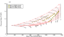
There are two different ways around the fan surge margin problem highlighted above: 1) Incorporate a variable area cold nozzle, possibly integrating it into the thrust reverser; 2) Specify a variable pitch fan, which may also provide a reverse thrust capability.
In the first option, the cold nozzle throat area is increased at low flight speeds, which drops the fan operating line away from the surge line. The fan surge line is unaffected.
With the second option, reducing the fan pitch tends to raise the surge pressure ratio for a given mass flow without affecting the position of the fan operating lines (e.g. low and high flight speed). At a given flow, the fan has to run faster because the pitch reduction reduces the fan swallowing capacity. There may also be an efficiency benefit. Typically the fan pitch would be scheduled to close progressively as the engine is throttled back. Consequently, the slope of effective surge line becomes shallower, in much the same way as closing variable stator vanes in a multi-stage compressor.
If the intermediate-pressure compressor is attached to the LP shaft there are IP compressor surge margin implications. Basically when a VP fan engine is throttled back, the reduction in fan pitch initially tends to keep the LP shaft speed at a high level. Naturally, the throttling process reduces the IPC flow, but it is at (roughly) constant IP corrected speed, so the IPC operating point drifts towards surge. At some point the scheduled reduction in fan pitch must be slowed (or even stopped momentarily) to enable LP speed to decrease, easing the IP compressor away from surge.
Reversing the fan pitch, air enters the bypass duct (via a secondary intake system) and flows forward mostly through the fan, but some is diverted though the core compression system to keep the gas generator functioning. The fan air is compressed and expelled out through the main air intake thus providing reverse thrust (even down to zero ground speed without stone ingestion). The pitch of the fan can be reversed through feather as in the Turbomeca Astafan.[1] or through fine pitch as employed in the Rolls-Royce/SNECMA M45SD-02.[2][3]
Engines
- Turbomeca Astafan
- Rolls-Royce/SNECMA M45H (SD-02 derivative)
- Rolls-Royce Trent (Proposed Ultrafan development)
Tentatives
- IAE SuperFan, an IAE V2500 derivative proposed for the Airbus A340 between 1987 and 1992
References
- ↑ FlightGlobal/Archivearticle:http://www.flightglobal.com/pdfarchive/view/1972/1972%20-%200931.html?search=Astafan
- ↑ FlightGlobal/Archivearticle:http://www.flightglobal.com/pdfarchive/view/1973/1973%20-%201027.html?search=M45SD-02
- ↑ FlightGlobal/Archivearticle:http://www.flightglobal.com/pdfarchive/view/1979/1979%20-%200130.html?search=M45SD-02