Valve audio amplifier technical specification
Technical specifications and detailed information on the valve audio amplifier, including its development history.
Circuitry and performance
Characteristics of valves
Valves (also known as vacuum tubes) are very high input impedance (near infinite in most circuits) and high-output impedance devices. They are also high-voltage / low-current devices.
The characteristics of valves as gain devices have direct implications for their use as. audio amplifiers, notably that power amplifiers need output transformers (OPTs) to translate a high-output-impedance high-voltage low-current signal into a lower-voltage high-current signal needed to drive modern low-impedance loudspeakers (cf. transistors and FETs which are relatively low voltage devices but able to carry large currents directly).
Another consequence is that since the output of one stage is often at ~100 V offset from the input of the next stage, direct coupling is normally not possible and stages need to be coupled using a capacitor or transformer. Capacitors have little effect on the performance of amplifiers. Interstage transformer coupling is a source of distortion and phase shift, and was avoided from the 1940s for high-quality applications; transformers also add cost, bulk, and weight.
Basic circuits
The following circuits are simplified conceptual circuits only, real world circuits also require a smoothed or regulated power supply, heater for the filaments (the details depending on if the selected valve types are directly or indirectly heated), and the cathode resistors are often bypassed, etc.
The common cathode gain stage
.png)
The basic gain stage for a valve amplifier is the auto-biased common cathode stage, in which an anode resistor, the valve, and a cathode resistor form a potential divider across the supply rails. The resistance of the valve varies as a function of the voltage on the grid, relative to the voltage on the cathode.
In the auto-bias configuration, the "operating point" is obtained by setting DC potential of the input grid at zero volts relative to ground via a high-value "grid leak" resistor. The anode current is set by the value of the grid voltage relative to the cathode and this voltage is now dependent upon the value of the resistance selected for the cathode branch of the circuit.
The anode resistor acts as the load for the circuit and is typically order of 3-4 times the anode resistance of the valve type in use. The output from the circuit is the voltage at the junction between the anode and anode resistor. This output varies relative to changes in the input voltage and is a function of the voltage amplification of the valve "mu" and the values chosen for the various circuit elements.
Almost all audio preamplifier circuits are built using cascaded common cathode stages.
The signal is usually coupled from stage to stage via a coupling capacitor or a transformer, although direct coupling is done in unusual cases.
The cathode resistor may or may not be bypassed with a capacitor. Feedback may also be applied to the cathode resistor.
The single-ended triode (SET) power amplifier
.gif)
A simple SET power amplifier can be constructed by cascading two stages, using an output transformer as the load.
Differential stages
Two triodes with the cathodes coupled together to form a differential pair. This stage has the ability to cancel common mode (equal on both inputs) signals, and if operated in class A also has the merit of having the ability to largely reject any supply variations (since they affect both sides of the differential stage equally), and conversely the total current drawn by the stage is almost constant (if one side draws more instantaneously the other draws less), resulting in minimal variation in the supply rail sag, and this possibly also interstage distortion.
Two power valves (may be triodes or tetrodes) being differentially driven to form a push–pull output stage, driving a push–pull transformer load. This output stage makes much better use of the transformer core than the single-ended output stage.
The long-tail pair
.gif)
A long tail is a constant current (CC) load as the shared cathode feed to a differential pair. In theory the more constant current linearises the differential stage.
The CC may be approximated by a resistor dropping a large voltage, or may be generated by an active circuit (either valve, transistor or FET based)
The long-tail pair can also be used as a phase splitter. It is often used in guitar amplifiers (where it is referred to as the "phase inverter") to drive the power section.
The concertina phase splitter
As an alternate to the long-tail pair, the concertina uses a single triode as a variable resistance within a potential divider formed by Ra and Rk either side of the valve. The result is that the voltage at the anode swings exactly and opposite to the voltage at the cathode, giving a perfectly balanced phase split. the disadvantage of this stage (cf the differential long-tail pair) is that it does not give any gain. Using a double triode (typically octal or noval) to form a SET input buffer (giving gain) to then feed a concertina phase splitter is a classic push–pull front end, typically followed by a driver (triode) and (triode or pentode) output stage (in ultra linear in many cases) to form the classic push–pull amplifier circuit.
The push–pull power amplifier
.gif)
The push–pull output circuit shown is a simplified variation of the Williamson topology, which comprises four stages:
- a SET input stage to buffer the input and give some voltage gain.
- a phase splitter, usually of the cathodyne or "concertina" type. This generates exactly equal but opposite drive signals for the following push–pull circuitry, but gives no gain. Note that as shown, the Williamson topology concertina phase splitter is direct coupled (with a resistor) to the input stage. This requires careful design of the input stage since the nominal voltage of the input valve anode will define the operating point of the concertina as well. Other topologies include the paraphase, floating paraphase and differential (long-tailed pair).
- a driver stage. This gives further voltage gain for each of the push–pull signals, and depending on the output stage valve's requirements may be a type selected for higher voltage or lower Z drive capability.
- The output stage, where the load is the transformer rather than an anode resistor. The original Williamson used KT66 pentodes "triode strapped" (operating as triodes). The majority of later push–pull amplifiers used the ultralinear connection instead.
Cascode

The word cascode is a contraction of the phrase cascade to cathode. The cascode is a two-stage amplifier composed of a transconductance amplifier followed by a current buffer. In valve circuits, the cascode is often constructed from two triodes connected in series, with one operating as a common grid and thus acting as a voltage regulator, providing a nearly constant anode voltage to the other, which operates as a common cathode. This improves input-output isolation (or reverse transmission) by eliminating the Miller effect and thus contributes to a much higher bandwidth, higher input impedance, high output impedance, and higher gain than a single-triode stage.
Tetrode/pentode stages
The tetrode has a screen grid (g2) which is between the anode and the first grid and normally serves, like the cascode, to eliminate the Miller effect and therefore also allows a higher bandwidth and/or higher gain than a triode, but at the expense of linearity and noise performance.
A pentode has an additional suppressor grid (g3) to eliminate the tetrode kink. This is used for improved performance rather than extra gain and is usually not accessible externally. Some of these valves use aligned grids to minimise grid current and beam plates instead of a third grid, these are known as "beam tetrodes".
It was realised (and many pentodes were specifically designed to permit) that by strapping the screens to the grid/anode a tetrode/pentode just became a triode again, as such making these late design valves very flexible. "Triode strapped" tetrodes are often used in modern amplifier designs that are optimised for quality rather than power output.
Ultra-linear
In 1937, Alan Blumlein originated a configuration between a "triode strapped" tetrode and normal tetrode, that connects the extra grid (screen) of a tetrode to a tap from the OPT part way between the anode voltage and the supply voltage. This electrical compromise gives a gain and linearity equal to the best traits of both extremes. In a 1951 engineering paper published by David Hafler and Herbert Keroes, they determined that when the screen tap was set to approximately 43% of anode voltage, an optimized condition within the output stage occurred, which they referred to as ultra-linear. By the late 1950s, this design became the dominant configuration for high-fidelity PP amplifiers.
Output transformerless
Julius Futterman pioneered a type of amplifier known as "output transformerless" (OTL). These use paralleled valves to match with speaker impedances (typically 8 ohms). This design require numerous valves, run hot, and because they attempt to match impedances in a way fundamentally different from a transformer, they often have a unique sound quality. 6080 triodes, designed for regulated power supplies, were low-impedance types sometimes pressed into transformerless use.
Single-ended triode (SET) power amplifiers
Some valve amplifiers use the single-ended triode (SET) topology that uses the gain device in class A. SETs are extremely simple and have low parts count. Such amplifiers are expensive because of the output transformers required.
This type of design results in an extremely simple distortion spectrum comprising a monotonically decaying series of harmonics. Some consider this distortion characteristic is a factor in the attractiveness of the sound such designs produce. Compared with modern designs SETs adopt a minimalist approach, and often have just two stages, a single stage triode voltage amplifier followed by a triode power stage. However, variations using some form of active current source or load, not considered a gain stage, are used.
The typical valve using this topology in (rare) current commercial production is the 300B, which yields about 5 watts in SE mode. Rare amplifiers of this type use valves such as the 211 or 845, capable of about 18 watts. These valves are bright emitter transmitting valves, and have thoriated tungsten filaments which glow like light bulbs when powered.
See paragraphs further down regarding high-power commercially available SET amplifers offering up to 40 watts with no difficulty, following the development of output transformers to overcome the above restrictions.
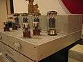
The pictures below are of a commercial SET amplifier, and also a prototype of a hobbyist amplifier.
 A commercial SE amplifier
 A prototype hobbyist constructed SET amplifier
One reason for SETs being (usually) limited to low power is the extreme difficulty (and consequent expense) of making an output transformer that can handle the plate current without saturating, while avoiding excessively large capacitive parasitics.
Push–pull (PP) / differential power amplifiers
The use of differential ("push–pull") output stages cancels standing bias current drawn through the output transformer by each of the output valves individually, greatly reducing the problem of core saturation and thus facilitating the construction of more powerful amplifiers at the same time as using smaller, wider bandwidth and cheaper transformers.
The cancellation of the differential output valves also largely cancels the (dominant) even-order harmonic distortion products of the output stage, resulting in less THD, albeit dominated now by odd-order harmonics and no longer monotonic.
Ideally, cancellation of even-order distortion is perfect, but it the real world it is not, even with closely matched valves. PP OPTs usually have a gap to prevent saturation, though less than required by a single-ended circuit.
Since the 1950s the vast majority of high-quality valve amplifiers, and almost all higher-power valve amplifiers have been of the push–pull type.
Push–pull output stages can use triodes for lowest Zout and best linearity, but often use tetrodes or pentodes which give greater gain and power. Many output valves such as KT88, EL34, and EL84 were specifically designed to be operated in either triode or tetrode mode, and some amplifiers can be switched between these modes. Post-Williamson, most commercial amplifiers have used tetrodes in the "ultra-linear" configuration.
Class A
Class A pure triode PP stages are sufficiently linear that they can be operated without feedback, although modest NFB to reduce distortion, reduce Zout, and control gain may be desirable. Their power efficiency is, however, much less than class AB (and, of course, class B); significantly less output power is available for the same anode dissipation.
Class A PP designs have no crossover distortion and distortion becomes negligible as signal amplitude is reduced. The effect of this is that class A amplifiers perform extremely well with music that has a low average level (with negligible distortion) with momentary peaks.
A disadvantage of Class A operation for power valves is a shortened life, because the valves are always fully "on" and dissipate maximum power all of the time. Voltage amplifier valves not operating at high power are not affected in this way.
Power supply regulation (variation of voltage available with current drawn) is not an issue, as current is essentially constant; AB amplifiers, which draw current dependent upon signal level, require attention to supply regulation.
Class AB and B
Class B and AB amplifiers are more efficient than class A, and can deliver higher power output levels from a given power supply and set of valves.
However, the price for this is that they suffer from crossover distortion, of more or less constant amplitude regardless of signal amplitude. This means that class AB and B amplifiers produce their lowest distortion percentage at near maximum amplitude, with poorer distortion performance at low levels. As the circuit changes from pure class A, through AB1 and AB2, to B, open-loop crossover distortion worsens.
Class AB and B amplifiers use NFB to reduce open-loop distortion. Measured distortion spectra from such amplifiers show that distortion percentage is dramatically reduced by NFB, but the residual distortion is shifted towards higher harmonics.
In a class B push–pull amplifier, output valve current which must be provided by the power supply ranges from nearly zero for zero signal to a maximum at maximum signal. Consequently, for linear response to transient signal changes the power supply must have good regulation.
Only class A can be used in single-ended mode, as part of the signal would otherwise be cut off. The driver stage for class AB2 and B valve amplifiers must be capable of supplying some signal current to the power valve grids ("driving power").
Biasing
The biasing of a push–pull output stage can be adjusted (at the design stage, usually not in a finished amplifier) between class A (giving best open-loop linearity) through classes AB1 and AB2, to class B (giving greatest power and efficiency from a given power supply, output valves and output transformer).
Most commercial valve amplifiers operate in Class AB1 (typically pentodes in the ultra-linear configuration), trading open-loop linearity against higher power; some run in pure class A.
Circuit topology
The typical topology for a PP amplifier has an input stage, a phase splitter, a driver and the output stage, although there are many variations of the input stage / phase splitter, and sometimes two of the listed functions are combined in one valve stage. The dominant phase splitter topologies today are the concertina, floating paraphase, and some variation of the long-tail pair.
The gallery shows a modern home-constructed, fully differential, pure class A amplifier of about 15 watts output power without negative feedback, using 6SN7 low-power dual triodes and KT88 power tetrodes.
Output transformers
Because of their inability to drive low impedance loads directly, valve audio amplifiers must employ output transformers to step down the impedance to match the loudspeakers.
Output transformers are not perfect devices and will always introduce some odd harmonic distortion and amplitude variation with frequency to the output signal. In addition, transformers introduce frequency-dependent phase shifts which limit the overall negative feedback which can be used, to keep within the Nyquist stability criteria at high frequencies and avoid oscillation. In recent years, however, the development of improved transformer designs and winding techniques greatly reduce these unwanted effects within the desired pass-band, moving them further out to the margins.
Negative feedback (NFB)
Following its invention by Black, negative feedback (NFB) has been almost universally adopted in amplifiers of all types, to substantially reduce distortion, flatten frequency response, and reduce the effect of component variations. This is especially needed with non-class-A amplifiers.
Feedback very much reduces distortion percentage, but the distortion spectrum becomes more complex, with a far higher contribution from higher harmonics;[1] the high harmonics, if at an audible level, are much more undesirable than lower ones,[1] so that the improvement due to lower overall distortion is partly cancelled by its nature. It is reported that under some circumstances the absolute amplitude of higher harmonics may increase with feedback, although total distortion decreases.[1]
NFB reduces output impedance (Zout) (which may vary as a function of frequency in some circuits). This has two important consequences:
- Loudspeakers that have impedance versus frequency functions that deviate substantially from flat will develop substantially non-flat frequency responses when used with High Zout amplifiers.
Valve noise and noise figure
Like any amplifying device, valves add noise to the signal to be amplified. Noise is due to device imperfections plus unavoidable temperature-dependent thermal fluctuations (systems are usually assumed to be at room temperature, T = 295 K). Thermal fluctuations cause an electrical noise power of , where is the Boltzmann constant and B the bandwidth. Correspondingly, the voltage noise of a resistance R into an open circuit is and the current noise into a short circuit is .


The noise figure is defined as the ratio of the noise power at the output of the amplifier to the noise power that would be present at the output if the amplifier were noiseless (due to amplification of thermal noise of the signal source). An equivalent definition is: noise figure is the factor by which insertion of the amplifier degrades the signal to noise ratio. It is often expressed in decibels (dB). An amplifier with a 0 dB noise figure would be perfect.
The noise properties of valves at audio frequencies can be modelled well by a perfect noiseless valve having a source of voltage noise in series with the grid. For the EF86 low-noise audio pentode valve, for example, this voltage noise is specified (see e.g., the Valvo, Telefunken or Philips data sheets) as 2 microvolts integrated over a frequency range of approximately 25 Hz to 10 kHz. (This refers to the integrated noise, see below for the frequency dependence of the noise spectral density.) This equals the voltage noise of a 25 kΩ resistor. Thus, if the signal source has an impedance of 25 kΩ or more, the noise of the valve is actually smaller than the noise of the source. For a source of 25 kΩ, the noise generated by valve and source are the same, so the total noise power at the output of the amplifier is the square root of two times the noise power at the output of the perfect amplifier. It is not simply double because the noise sources are random and there is some partial cancellation in the combined noise. The noise figure is then 1.414, or 1.5 dB. For higher impedances, such as 250 kΩ, the EF86's voltage noise is 1/101/2 lower than the sources's own noise, and the noise figure is ~1 dB. For a low-impedance source of 250 Ω, on the other hand, the noise contribution of the valve is 10 times larger than the signal source, and the noise figure is approximately ten, or 10 dB.
To obtain low noise figure, the impedance of the source can be increased by a transformer. This is eventually limited by the input capacitance of the valve, which sets a limit on how high the signal impedance can be made if a certain bandwidth is desired.
The noise voltage density of a given valve is a function of frequency. At frequencies above 10 kHz or so, it is basically constant ("white noise"). White noise is often expressed by an equivalent noise resistance, which is defined as the resistance which produces the same voltage noise as present at the valve input. For triodes, it is approximately (2-3)/gm, where gm is the transconductivity. For pentodes, it is higher, about (5-7)/gm. Valves with high gm thus tend to have lower noise at high frequencies.
In the audio frequency range (below 1–100 kHz), "1/f" noise becomes dominant, which rises like 1/f. Thus, valves with low noise at high frequency do not necessarily have low noise in the audio frequency range. For special low-noise audio valves, the frequency at which 1/f noise takes over is reduced as far as possible, maybe to something like a kilohertz. It can be reduced by choosing very pure materials for the cathode nickel, and running the valve at an optimized (generally low) anode current.
Microphony
Unlike solid-state devices, valves are assemblies of mechanical parts whose arrangement determines their functioning, and which cannot be totally rigid. If a valve is jarred, either by the equipment being moved or by acoustic vibrations from the loudspeakers, or any sound source, it will produce an output signal, as if it were some sort of microphone (the effect is consequently called microphony). All valves are subject to this to some extent; low-level voltage amplifier valves for audio are designed to be resistant to this effect, with extra internal supports. The EF86 mentioned in the context of noise is also designed for low microphony, though its high gain makes it particularly susceptible.
Modern audiophile hi-fi amplification
For high-end audio, where cost is not the primary consideration, valve amplifiers have remained popular and indeed during the 1990s made a commercial resurgence.
Circuits designed since then in most cases remain similar to circuits from the valve age, but benefit from advances in ancillary component quality (including capacitors) as well as general progress across the electronics industry which gives designers increasingly powerful insight into circuit operation. Solid-state power supplies are more compact, efficient, and can have very good regulation.
Semiconductor power amplifiers do not have the severe limitations on output power imposed by thermionic devices; accordingly loudspeaker design has evolved in the direction of smaller. more convenient, loudspeakers, trading off power efficiency for small size, giving speakers of similar quality but smaller size which require much greater power for the same loudness than hitherto. In response, many modern valve push–pull amplifiers are more powerful than earlier designs, reflecting the need to drive inefficient speakers.
Modern valve preamplifiers
When valve amplifiers were the norm, user-adjustable "tone controls" (a simple two-band non-graphic equaliser) and electronic filters were used to allow the listener to change frequency response according to taste and room acoustics; this has become uncommon. Some modern equipment uses graphic equalisers, but valve preamplifiers tend not to supply these facilities (except for RIAA and similar equalisation needed for vinyl and shellac discs).
Modern signal sources, unlike vinyl discs, supply line level signals without need for equalisation. It is common to drive valve power amps directly from such source, using passive volume and input source switching integrated into the amplifier, or with a minimalist "line level" control amplifier which is little more than passive volume and switching, plus a buffer amplifier stage to drive the interconnects.
However, there is some small demand for valve preamps and filter circuits for studio microphone amplifiers, equalising preamplifiers for vinyl discs, and exceptionally for active crossovers.
Modern valve power amplifiers
Commercial single-ended triode amplifiers
When valve amplifiers were the norm, SETs more-or-less disappeared from western products except for low-power designs (up to 5 watts), with push–pull indirectly heated triodes or triode-connected valves such as EL84 becoming the norm.
However, the far east never abandoned valves, and especially the SET circuit; indeed the extreme interest in all things audiophile in Japan and other far eastern countries sustained great interest in this approach.
- One of the key connections between this far-eastern attitude towards the SET, and the west was Jean Hiraga, longtime editor of l'audiophile in France (and in French).[2]
- A very extreme example of an almost "zen" or "poetic" approach to amplifier design in the far east—very different from the Western engineering-led approach—is the work of Susumu Sakuma,[3] although Sakuma's designs are far from mainstream
Since the 1990s a niche market has developed again in the west for low-power commercial SET amplifies (up to 7 watts), notably using the 300B valve in recent years, which has become fashionable and expensive. Lower-power amplifiers based on other vintage valve types such as 2A3 and 45 are also made.
Even more rarely, higher powered SETs are produced commercially, usually using the 211 or 845 transmitting valves, which are able to deliver 20 watts, operating at 1000 V. Notable amplifiers in this class are those from Audio Note corporation (designed in Japan), including the "Ongaku", voted amplifier of the year during the late 1990s. A very small number of hand-built products of this class sell at very high prices (from US$10,000). The Wavac 833 may be the world's most expensive hi-fi amplifier, delivering around 150 watts using an 833A valve.
Aside from this Wavac and a very few other high-power SETs, SET amplifiers usually need to be carefully paired with very efficient speakers, notably horn and transmission-line enclosures and full-range drivers such as those made by Klipsch and Lowther, which invariably have their own quirks, offsetting their advantages of very high efficiency and minimalism.
Some companies such as the Chinese company "Ming Da" make low power SETs using valves other than the 300B, such as KT90 (a development of the KT88) and up to the more powerful sister of the 845, the 805ASE, with output power of 40 watts over the full audio range from 20 Hz. This is made possible by an output transformer design which does not saturate at high levels and has high efficiency.
Commercial push–pull (PP) amplifiers
Mainstream modern loudspeakers give good sound quality in a compact size, but are much less power-efficient than older designs and require powerful amplifiers to drive them. This makes them unsuitable for use with valve amplifiers, particularly lower-power single-ended designs. Valve hi-fi power amplifier designs since the 1970s have had to move mainly to class AB1 push–pull (PP) circuits. Tetrodes and pentodes, sometimes in ultra-linear configuration, with significant negative feedback, are the usual configuration.
Some class A push–pull amplifiers are made commercially. Some amplifiers can be switched between classes A and AB; some can be switched into triode mode.
Major manufacturers in the PP valve market include:
- Audio Research
- Cary Audio Design
- Jadis
- Ming Da
- McIntosh
Hobbyist amplifier construction
The simplicity of valve amplifiers, especially single-ended designs, makes them viable for home construction. This has some advantages:
- Being able to use highly regarded valves produced many years ago and are only available in ones and twos;
- The home constructor can experiment with different component types, or different samples of a component.
Construction
Point-to-point hand-wiring tends to be used rather than circuit boards in low-volume high-end commercial constructions as well as by hobbyists. This construction style is satisfactory due to ease of construction, adapted to the number of physically large and chassis mounted components (valve sockets, large supply capacitors, transformers), the need to twist heater wiring to minimise hum, and as a side effect benefiting from the fact that "flying" wiring minimises capacitive effects.
One picture below shows circuit constructed using "standard" modern industrial parts (630 V MKP capacitors/metal film resistors). One advantage a hobbyist has over a commercial producer is the ability to use higher quality parts that are not reliably available in production volumes (or at a commercially viable cost price). For example, the "silver top getter" Sylvania brown base 6SN7s in use in the external picture date from the 1960s.
Another picture shows exactly the same circuit constructed using Russian military production Teflon capacitors and non-inductive planar film resistors, of the same values.
The wiring of a commercial amplifier is also shown for comparison
 External view
 Schematic
 Internals using normal industrial quality parts.
 Internals using "up-spec" Teflon caps and planar resistors.
 Internal construction of a commercial PP amplifier
Unusual designs
Very high power SETs
Very occasionally, very-high-power valves (usually designed for use in radio transmitters) from decades ago are pressed into service to create one-off SET designs (usually at very high cost). Examples include valves 211 and 833.
The main problem with these designs is constructing output transformers able to sustain the plate current and resultant flux density without core saturation over the full audio-frequency spectrum. This problem increases with power level.
Another problem is that the voltages for such amplifiers often pass well beyond 1 kV, which forms an effective disincentive to commercial products of this type.
Parallel push–pull (PPP) amplifiers

Many modern commercial amplifiers (and some hobbyist constructions) place multiple pairs of output valves of readily obtainable types in parallel to increase power, operating from the same voltage required by a single pair. A beneficial side effect is that the output impedance of the valves, and thus the transformer turns ratio needed, is reduced, making it easier to construct a wide bandwidth transformer.
Some high-power commercial amplifiers use arrays of standard valves (e.g. EL34, KT88) in the parallel push–pull (PPP) configuration (e.g. Jadis, Audio Research, McIntosh, Ampeg SVT).
Some home-constructed amplifiers use pairs of high-power transmitting valves (e.g. 813) to yield 100 watts or more of output power per pair in class AB1 (ultra-linear).
Output transformerless amplifiers (OTL)
The output transformer (OPT) is a major component in all mainstream valve power amplifiers, accounting for significant cost, size, and weight. It is a compromise, balancing the needs for low stray capacitance, low losses in iron and copper, operation without saturation at the required direct current, good linearity, etc.
One approach to avoid the problems of OPTs is to avoid the OPT entirely, and directly couple the amplifier to the loudspeaker, as is done with most solid-state amplifiers. Some designs without output transformers (OTLs) were produced by Julius Futterman in the 1960s and '70s, and more recently in different embodiments by others.
Valves normally match much higher impedances than that of a loudspeaker. Low-impedance valve types and purpose-designed circuits are required. Reasonable efficiency and moderate Zout (damping factor) can be achieved.
These effects mean that OTLs have selective speaker load requirements, just like any other amplifier. Generally a speaker of at least 8 ohms is required, although larger OTLs are often quite comfortable with 4 ohm loads. Electrostatic speakers (often considered difficult to drive) often work especially well with OTLs.
The more recent and more successful OTL circuits employ an output circuit generally known as a Circlotron. The Circlotron has about one-half the output impedance of the Futterman-style (totem-pole) circuits. The Circlotron is fully symmetrical and does not require large amounts of feedback to reduce output impedance and distortion. Successful embodiments use the 6AS7G and the Russian 6C33-CB power triodes.
A common myth is that a short-circuit in an output valve may result in the loudspeaker being connected directly across the power supply and destroyed. In practice, the older Futterman-style amplifiers have been known to damage speakers, due not to shorts but to oscillation. The Circlotron amplifiers often feature direct-coupled outputs, but proper engineering (with a few well-placed fuses) ensures that damage to a speaker is no more likely than with an output transformer.
Modern OTLs are often more reliable, sound better, and are less expensive than many transformer-coupled valve approaches.
Direct coupled amplifiers for electrostatics and headphones
In a sense this niche is a subset of OTLs however it merits treating separately because unlike an OTL for a loudspeaker, which has to push the extremes of a valve circuit's ability to deliver relatively high currents at low voltages into a low impedance load, some headphone types have impedances high enough for normal valve types to drive reasonably as OTLs, and in particular electrostatic loudspeakers and headphones which can be driven directly at hundreds of volts but minimal currents.
Once more there are some safety issues associated with direct drive for electrostatic loudspeakers, which in extremis may use transmitting valves operating at over 1 kV. Such systems are potentially lethal.
See also
Notes
References
- Colloms, Martin. A Future Without Feedback? in Stereophile, January, 1998
- Glass Audio. A long-running journal devoted to valve amplifier construction, published by Audio Amateur Corporation, Peterborough, New Hampshire
- Jones, Morgan. Valve Amplifiers, Third Edition, 2003. ISBN 0-7506-5694-8
- Kavsek, Paul G. Röhrenverstärker: Klang und Form. Vienna: Allegro Verlag, 1995. ISBN 3-901462-00-7
- Langford-Smith, F. Radiotron Designer's Handbook. 4th edition 1952, Wireless Press, (first edition was published in 1934). Reprinted as Radio Designer's Handbook Newnes 1999, ISBN 0-7506-3635-1
- Tube Lovers Anonymous. 6C33C-B OTL Amplifier - Background and OTL Circuits