Upwind differencing scheme for convection
The upwind differencing scheme is a method used in numerical methods in computational fluid dynamics for convection–diffusion problems. This scheme is specific for Peclet number greater than 2 or less than −2
Description
By taking into account the direction of the flow, the upwind differencing scheme overcomes that inability of the central differencing scheme. This scheme is developed for strong convective flows with suppressed diffusion effects. Also known as ‘Donor Cell’ Differencing Scheme, the convected value of property ф at the cell face is adopted from the upstream node.
It can be described by Steady convection-diffusion partial Differential Equation[1][2] –


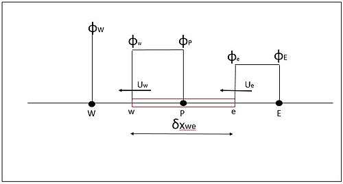
where is density, is diffusion coefficient, is the velocity vector, is the property to be computed, is the source term, and the subscripts and refer to the "east" and "west" faces of the cell (see Fig. 1 below).


After discretization, applying continuity equation, and taking source term equals to zero we get[5]
Central difference discretized equation
- .[6].....(1)


- [7].....(2)

Lower case denotes the face and upper case denotes node; , , and refer to the "East," "West," and "Central" cell. (again, see Fig. 1 below).


Defining variable F as convection mass flux and variable D as diffusion conductance
- and


Peclet number (Pe) is a non-dimensional parameter determining the comparative strengths of convection and diffusion
Peclet number:

For a Peclet number of lower value (|Pe| < 2, diffusion is dominant and for this we use the central difference scheme. For other values of and upwind scheme is used for convection dominating flows with Peclet number (|Pe| > 2).
For positive flow direction


Corresponding upwind scheme equation:
- [8].....(3)

Due to strong convection and suppressed diffusion


Rearranging equation (3) gives
![[(D_{w}+F_{w})+ D_{e}+ (F_{e}-F_{w})]\phi_{P}\, =(D_{w}+F_{w})\phi_{W}+D_{e}\phi_{E})](../I/m/a3633f9000fb62fbc9e6d4766c5b02f49be5e889.svg)
Identifying coefficients,
![a_{P}\,= [(D_{w} + F_{w}) + D_{e} + (F_{e} - F_{w})]](../I/m/252b5977340f67850e959c0d5fea0031eb55f867.svg)


For negative flow direction


Corresponding upwind scheme equation:
- [10].....(4)


Rearranging equation(4) gives
![[( D_e - F_e ) + D_w + ( F_e - F_w )] \phi_{P} = D_w \phi_{W} + ( D_e - F_e ) \phi_{E}](../I/m/5c95ebdb8733f709dc0edf9e53e8ed24f60d10f0.svg)
Identifying coefficients,


We can generalize coefficients as[11] –


Use
Solution in the central difference scheme fails to converge for Peclet number greater than 2 which can be overcome by using an upwind scheme to give a reasonable result.[12][13] Therefore the upwind differencing scheme is applicable for Pe > 2 for positive flow and Pe < −2 for negative flow. For other values of Pe, this scheme doesn’t give effective solution.
Assessment
Conservativeness[14]
The upwind differencing scheme formulation is conservative.
Boundedness[15]
As the coefficients of the discretised equation are always positive hence satisfying the requirements for boundedness and also the coefficient matrix is diagonally dominant therefore no irregularities occur in the solution.

Transportiveness[16]
Transportiveness is built into the formulation as the scheme already accounts for the flow direction.
Accuracy
Based on the backward differencing formula, the accuracy is only first order on the basis of the Taylor series truncation error. It gives error when flow is not aligned with grid lines. Distribution of transported properties become marked giving diffusion-like appearance, called as the false diffusion. Refinement of grid serves in overcoming the issue of false diffusion. With decrease in the grid size, false diffusion decrease thus increasing the accuracy.
References
- ↑ H.K Versteeg & W. Malalasekera (1995). An introduction to Computational Fluid Dynamics.Chapter:5, Page103.
- ↑ Central differencing scheme#Steady-state convection diffusion equation
- ↑ H. K. Versteeg & W. Malalasekera (1995). An introduction to Computational Fluid Dynamics. Chapter 5, page 104.
- ↑ Central differencing scheme#Formulation of Steady state convection diffusion equation
- ↑ Central differencing scheme#Formulation of Steady state convection diffusion equation
- ↑ H.K Versteeg & W. Malalasekera. An introduction to Computational Fluid Dynamics.Chapter:5. Page 105.
- ↑ H.K Versteeg & W. Malalasekera . An introduction to Computational Fluid Dynamics.Chapter:5. Page 105.
- ↑ H.K Versteeg & W. Malalasekera . An introduction to Computational Fluid Dynamics.Chapter:5.Page 115.
- ↑ H. K. Versteeg & W. Malalasekera ). An Introduction to Computational Fluid Dynamics, Chapter 5, page 115.
- ↑ H.K Versteeg & W. Malalasekera. An introduction to Computational Fluid Dynamics.Chapter:5. Page115.
- ↑ H. K. Versteeg & W. Malalasekera. An Introduction to Computational Fluid Dynamics, Chapter 5, page 116.
- ↑ H.K Versteeg & W. Malalasekera . An introduction to Computational Fluid Dynamics.Chapter:5. Figure 5.5.
- ↑ H.K Versteeg & W. Malalasekera . An introduction to Computational Fluid Dynamics.Chapter:5. Figure 5.13.
- ↑ H.K Versteeg & W. Malalasekera . An introduction to Computational Fluid Dynamics.Chapter:5.Page 118(5.6.1.1).
- ↑ H.K Versteeg & W. Malalasekera . An introduction to Computational Fluid Dynamics.Chapter:5.Page 118 (5.6.1.2).
- ↑ H. K. Versteeg & W. Malalasekera (1995). An Introduction to Computational Fluid Dynamics, Chapter 5, page 118. (5.6.1.3)