Undercut (manufacturing)
In manufacturing, an undercut is a special type of recessed surface. In turning, it refers to a recess in a diameter. In machining, it refers to a recess in a corner. In molding, it refers to a feature that cannot be molded using only a single pull mold. In printed circuit board, construction it refers to the portion of the copper that is etched away under the photoresist. In welding, it refers to undesired melting and removal of metal near the weld bead.
Turning
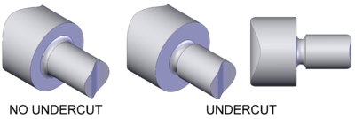
On turned parts an undercut is also known as a neck. They are often used at the end of the threaded portion of a shaft or screw to provide clearance for the cutting tool, and also referred to as thread relief in this context. A rule of thumb is that the undercut should be at least 1.5 threads long and the diameter should be at least 0.015 in (0.38 mm) smaller than the minor diameter of the thread.[1] Strictly speaking the relief simply needs to be equal or slightly smaller than the minor diameter of the thread. Thread relief can also be internal on a bore, and then the relief needs to be larger than the major thread diameter. They are also often used on shafts that have diameter changes so that a mating part can seat against the shoulder. If an undercut is not provided there is always a small radius left behind even if a sharp corner is intended. These types of undercuts are called out on technical drawings by stating the width and either the depth or the diameter of the bottom of the neck.[2]
Molding

Undercut - Any indentation or protrusion in a shape that will prevent its withdrawal from a one-piece mold.
Undercuts on molded parts are features that prevent the part from being directly ejected from an injection molding machine. They are categorized into internal and external undercuts, where external undercuts are on the exterior of the part and interior undercuts are on the inside of the part. Undercuts can still be molded, but require a side action or side pull.[3] This is an extra part of the mold that moves separately from the two halves. These can increase the cost of the molded part due to an added 15 to 30% cost of the mold itself and added complexity of the molding machine.[3][4]
If the size of the undercut is small enough and the material is flexible enough a side action is not always required. In these cases the undercut is stripped or snapped out of the mold. When this is done usually a stripping plate or ring is used instead of stripper pins so that the part is not damaged. This technique can be used on internal and external undercuts.[3]
Milling

In milling the corners may be undercut to remove the radius that is usually left by the milling cutter. Examples of this use are linear bearings for square shafts (i.e. racks) and machined hexalobular sockets.
Etching

- An isotropic etchant that creates an undercut
- An anisotropic etchant leaves no undercut
Undercuts from etching are somewhat different than the undercuts explained above, because it is a side effect, not an intentional feature. Undercuts from etching can occur from two common causes. The first is over etching, which means the etchant was applied too long. The second is due to an isotropic etchant, which means the etchant etches in all directions equally. To overcome this problem an anisotropic etchant is used.[5]
Welding

Undercutting is when the weld reduces the cross-sectional thickness of the base metal. This type of defect reduces the strength of the weld and workpieces. One reason for this defect is excessive current, causing the edges of the joint to melt and drain into the weld; this leaves a drain-like impression along the length of the weld. Another reason is if a poor technique is used that does not deposit enough filler metal along the edges of the weld. A third reason is using an incorrect filler metal, because it will create greater temperature gradients between the center of the weld and the edges. Other causes include too small of an electrode angle, a dampened electrode, excessive arc length, and slow speed.[6]
Gears
References
- ↑ "Thread relief and chamfers". PMPA's Designer's Guide. Precision Machined Products Association. Retrieved 2009-07-19.
- ↑ Taylor 2004, p. 194.
- 1 2 3 Berins & Society of the Plastics Industry 1991, pp. 325–326.
- ↑ Rosato et al. 2001, pp. 1405–1406.
- ↑ Degarmo, Black & Kohser 2003, p. 897.
- ↑ Rampaul 2003, pp. 211–212.
Bibliography
- Berins, Michael L.; Society of the Plastics Industry (1991), SPI plastics engineering handbook of the Society of the Plastics Industry, Inc. (5th ed.), Springer, ISBN 978-0-412-99181-3.
- Degarmo, E. Paul; Black, J T.; Kohser, Ronald A. (2003), Materials and Processes in Manufacturing (9th ed.), Wiley, ISBN 0-471-65653-4.
- Rosato, Dominick V.; Plastics Institute of America; Schott, Nick R.; Rosato, Marlene G. (2001), Plastics Engineering, Manufacturing & Data Handbook, Springer, ISBN 978-0-7923-7316-2.
- Taylor, David L. (2004), Machine Trades Blueprint Reading (2nd ed.), Cengage Learning, ISBN 978-1-4018-9998-1.