Twinaxial cabling
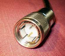
Twinaxial cabling, or "Twinax", is a type of cable similar to coaxial cable, but with two inner conductors instead of one. Due to cost efficiency it is becoming common in modern (2013) very-short-range high-speed differential signaling applications.
Legacy applications
IBM
Historically, Twinax was the cable specified for the IBM 5250 terminals and printers, used with IBM's System/34, System/36, System/38, and IBM System i (formerly known as AS/400) midrange hosts, and with IBM Power Systems machines running IBM i. The data transmission is half-duplex, balanced transmission, at 1 Mbit/s, on a single shielded, 110 Ω twisted pair.[1]
With Twinax seven devices can be addressed, from workstation address 0 to 6. The devices do not have to be sequential.
Twinax is a bus topology that requires termination to function properly. Most Twinax T-connectors have an automatic termination feature. For use in buildings wired with Category 3 or higher twisted pair there are baluns that convert Twinax to twisted pair and hubs that convert from a bus topology to a star topology.
Twinax was designed by IBM. Its main advantages were high speed (1 Mbit/s versus 9600 bit/s) and multiple addressable devices per connection. The main disadvantage was the requirement for proprietary Twinax cabling with bulky screw-shell connectors.
Physical layer
Signals are sent differentially over the wires at 1 Mbit/s (1 μs/bit ± 2%), Manchester coded, with preemphasis.[2] The signal coding is only approximately differential and not completely differentially balanced. In general, one of the two signal lines is driven to −0.32 V ± 20%, while the other carries 0 V. This, itself, could be considered as two differential signals of ±0.16 V superimposed on a −0.16 V common mode level. However, to provide preemphasis, for the first 250 ns (1/4 bit time) after a signal is driven low, the negative signal line is driven to −1.6 V. During this time, the common-mode voltage is −0.8 V.
This signal is designed to provide a minimum of ±100 mV at the end of 152 m (500 feet) of cable.
The two wires are denoted A and B. To encode a 0 bit, A>B for the first half of the bit time, and A<B for the second half. A 1 bit is the opposite. Thus, each signal line is driven low for either 500 or 1000 ns at a time, of which the first 250 ns is emphasized.
Data link layer
A message begins with five normal 1 bits (A driven low for 500 ns, then B driven low for 500 ns) for bit synchronization, followed by a special frame sync pattern, three bit times long, that violates the usual Manchester encoding rules. A is driven low for 1500 ns, then B is driven low for 1500 ns. This is like a 1 bit sent at 1/3 normal speed (although the preemphasis pulses remain 250 ns long).[2][3]
This pattern is followed by up to 256 16-bit data frames. Each data frame consists of a start bit of 1, an 8-bit data field, a 3-bit station address, and an even parity bit (which includes the start bit, so it equivalent to odd parity over the data and address fields only). This is then followed by three or more fill bits of 0. Unusually for an IBM protocol, the bits within each frame are sent lsbit-first.[3]
All messages are sent between the controller (master) and one slave device. The first frame in a message from the controller contains the device's address, from 0 to 6. The address field of following frames can be any value from 0 to 6, although is usually set to the device's address as well. The final frame in a message includes an address of 7 (all ones) as an end-of-message (EOM) indicator. A single-frame message does not have an EOM indicator.
When a command calls for a response, the device is expected to respond in 30 to 80 μs. A device's response also consists of up to 256 frames, and includes its address in all frames but the last. In this case, a single-frame response includes the EOM address, and the controller assumes it comes from the device it most recently addressed.
Generally, the first frame in a message is a command byte, and following frames are associated data.[3][4]
NEC
NEC Astra system also uses this kind of cable for networking.
MIL-STD-1553
MIL-STD-1553 specifies that the data bus should have characteristic impedance between 70 and 85 ohms, while the industry has standardized on 78 ohms. Likewise, the industry has generally standardized on the cable known as Twinax cable that has a characteristic impedance of 78 ohms.
Current applications
SFP+ Direct-Attach Copper (10GSFP+Cu)

This is a copper 10 Gigabit Ethernet cable which comes in either an active or passive Twinax (twinaxial) cable assembly and connects directly into an SFP+ housing. An active Twinax cable has active electronic components in the SFP+ housing to improve the signal quality; a passive Twinax cable is mainly just a straight "wire" and contains few components. Generally, Twinax cables shorter than 5 meters are passive and those longer than 5 meters are active, but this may vary from vendor to vendor. SFP+ Direct Attach Copper (DAC) is a popular choice for 10G Ethernet reaches up to 10 m[5] due to low latency and low cost.
One of major applications includes Brocade, Arista, Cisco and others' network hardware with SFP+ interfaces. This type of connection is able to transmit at 10 gigabits/second full duplex speed over 5 meter distances. Moreover, this setup offers 15 to 25 times lower transceiver latency than current 10GBASE-T Cat 6/Cat 6a/Cat 7 cabling systems: 0.1 μs for Twinax with SFP+ versus 1.5 to 2.5 μs for current 10GBASE-T specification. The power draw of Twinax with SFP+ is around 0.1 watts, which is also much better than 4–8 watts for 10GBASE-T.
As always with cabling one of the consideration points is bit error ratio or BER for short. Twinax copper cabling has BER better than 10−18 according to Cisco, and therefore is acceptable for applications in critical environments.
| AWG cable size | Sustained bend radius |
|---|---|
| 24 | 1.5 inches (38 mm) |
| 26 | 1.3 inches (33 mm) |
| 28 | 1.0 inch (25 mm) |
| 30 | 0.9 inches (23 mm) |
Cables must not be bent below their minimum bend radius,[6][7] which depends upon cable size as expressed in AWG. The table on the right summarizes minimum values typically admitted for SFP+ sustained bend radiuses.
This SFP+ Twinax DAC is also referred to as "10GBASE-CR" by some manufacturers,[8] even though there is no IEEE or other standard with that name.
100 Gbit Ethernet
40GBASE-CR4 and 100GBASE-CR10 physical layers using 7 m twin-axial cable are being developed as part of 100 Gbit Ethernet specifications by IEEE 802.3bj workgroup.
SATA 3.0 cables
SATA 3.0 cables are implemented using Twinax (twinaxial cable).
DisplayPort
Many manufacturers of DisplayPort cabling are also using Twinax configurations to accommodate the strict insertion loss, return loss, and crosstalk requirements for the 2.7 Gbit/s signaling rate.
MIL-STD-1553
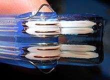
The cable used to connect the MIL-STD-1553 bus and stub devices has a characteristic impedance of 78 ohms at 1 MHz. A 2-conductor twisted-pair cable known as Twinax is used to connect the bus and stub devices. The insulated pairs are balanced and have an overall shielding braid around the pairs. The twisting of the signal-carrying pairs theoretically cancels any random induced noise caused by the pair. The two internal dielectric fillers separate the braid from the pairs to minimize the leakage capacitance to ground. The fillers also assist in uniform twisting of the pairs. The 90% braid coverage protects the pair from external noise. PVC outer jacket cable is suitable for lab use while high-temperature rated outer jacket cable is applicable for vehicle use.
See also
References
- ↑ "NLynx Technologies - what is Twinax?". NLynx. 2006.
- 1 2 Quigley, Thomas J. (March 1988), Interfacing the DP8344 to Twinax (PDF), National Semiconductor, AN-516
- 1 2 3 Twinax Cable Information, Anzac Computer Equipment Corporation, 2004-07-22, retrieved 2009-01-30
- ↑ Norcross, Thomas; Patchen, Paul J.; Quigley, Thomas J.; Short, Tim; Worsley, Debra; Johnson, Laura (April 1995), MPA-II—A Multi-Protocol Terminal Emulation Adapter Using the DP8344 (PDF), National Semiconductor, AN-641
- ↑ "10 gigabit Ethernet - alphabet soup never tasted so good". Archived from the original on 2009-08-16. Retrieved 2009-08-13.
- ↑ "Recommended minimum bend radii for QSFP+ and SFP+ cables". Retrieved 2014-04-24.
- ↑ "Temporary and Sustained Bend Radii for GORE™ SFP+ cables" (PDF). Retrieved 2014-04-24.
- ↑ "Arista Networks Transceivers & Cables". Retrieved 2012-03-28.
External links
- Cisco 10GBASE SFP+ Modules
- MIL-STD-1553B Concepts and Considerations from MilesTek Corporation