Triode

A triode is an electronic amplifying vacuum tube (or valve in British English) consisting of three electrodes inside an evacuated glass envelope: a heated filament or cathode, a grid, and a plate (anode). Developed from Lee De Forest's 1906 Audion radio wave detector, a partial vacuum tube that added a grid electrode to the thermionic diode (Fleming valve), the triode was the first practical electronic amplifier and the ancestor of other types of vacuum tubes such as the tetrode and pentode. Its invention founded the electronics age, making possible amplified radio technology and long-distance telephony. Triodes were widely used in consumer electronics devices such as radios and televisions until the 1970s, when transistors replaced them. Today, their main remaining use is in high-power RF amplifiers in radio transmitters and industrial RF heating devices. In recent years there has been a resurgence in demand for low power triodes due to renewed interest in tube-type audio systems by audiophiles who prefer its sound.
The word "triode" is derived from the Greek τρίοδος, tríodos, from tri- (three) and hodós (road, way), originally meaning the place where three roads meet.
History

The first vacuum tube used in radio[1][2] was the thermionic diode or Fleming valve, invented by John Ambrose Fleming in 1904 as a detector for radio receivers. It was an evacuated glass bulb containing two electrodes, a heated filament and a plate (anode). Triodes came about in 1906 when American engineer Lee De Forest[3] and Austrian physicist Robert von Lieben[4] independently patented tubes that added a third electrode, a grid between the filament and plate to control current.[5][6] von Lieben's partially-evacuated three-element tube, patented in March 1906, contained a trace of mercury vapor and was intended to amplify weak telephone signals.[7][8][9][4] Starting in October 1906[5] De Forest patented a number of three-element tube designs by adding an electrode to the diode, which he called Audions, intended to be used as radio detectors.[10][3] The one which became the design of the triode, in which the grid was located between the filament and plate, was patented January 29, 1907.[11][3][12] Like the von Lieben vacuum tube, De Forest's Audions were incompletely evacuated and contained some gas at low pressure.[13][14] von Lieben's vacuum tube did not see much development due to his death 7 years after he invented it at the outbreak of World War I.[15]
De Forest's Audion did not see much use until its ability to amplify was recognized around 1912 by several researchers,[14][16] who used it to build the first successful amplifying radio receivers and electronic oscillators.[17][18] The many uses for amplification motivated its rapid development. By 1913 improved versions with higher vacuum were developed by Harold Arnold at American Telephone and Telegraph Company which had purchased the rights to the Audion from De Forest, and Irving Langmuir at General Electric, who named his tube the "Pliotron",[14][16] These were the first vacuum tube triodes.[13] The name triode appeared later, when it became necessary to distinguish it from other kinds of vacuum tubes with more or fewer elements (e.g. diodes, tetrodes, pentodes, etc.). There were lengthy lawsuits between De Forest and von Lieben, and De Forest and the Marconi Company, representing John Ambrose Fleming the inventor of the diode.
The discovery of the triode's amplifying ability in 1912 revolutionized electrical technology, creating the new field of electronics, the technology of active (amplifying) electrical devices. The triode was immediately applied to many areas of communication. Triode "continuous wave" radio transmitters replaced the cumbersome inefficient "damped wave" spark gap transmitters, allowing the transmission of sound by amplitude modulation (AM). Amplifying triode radio receivers, which had the power to drive loudspeakers, replaced weak crystal radios, which had to be listened to with earphones, allowing families to listen together. This resulted in the evolution of radio from a commercial message service to the first mass communication medium, with the beginning of radio broadcasting around 1920. Triodes made transcontinental telephone service possible. Vacuum tube triode repeaters, invented at Bell Telephone after its purchase of the Audion rights, allowed telephone calls to travel beyond the unamplified limit of about 800 miles. The opening by Bell of the first transcontinental telephone line was celebrated 3 years later, on January 25, 1915. Other inventions made possible by the triode were television, public address systems, electric phonographs, and talking motion pictures.
The triode served as the technological base from which later vacuum tubes developed, such as the tetrode (Walter Schottky, 1916) and pentode (Gilles Holst and Bernardus Dominicus Hubertus Tellegen, 1926), which remedied some of the shortcomings of the triode detailed below.
The triode was very widely used in consumer electronics such as radios, televisions, and audio systems until it was replaced in the 1960s by the transistor, invented in 1947, which brought the "vacuum tube" era started by the triode to a close. Today triodes are mostly used in high-power applications for which solid state semiconductor devices are unsuitable, such as radio transmitters and industrial heating equipment. However, more recently the triode and other vacuum tube devices have been experiencing a resurgence and comeback in high fidelity audio and musical equipment.
Construction
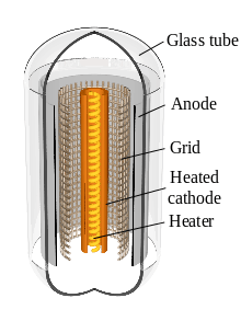

All triodes have a hot cathode electrode heated by a filament, which releases electrons, and a flat metal plate electrode to which the electrons are attracted, with a grid consisting of a screen of wires between them to control the current. These are sealed inside a glass container from which the air has been removed to a high vacuum, about 10−9 atm. Since the filament eventually burns out, the tube has a limited lifetime and is made as a replaceable unit; the electrodes are attached to terminal pins which plug into a socket. The operating lifetime of a triode is about 2000 hours for small tubes and 10,000 hours for power tubes.
Low power triodes
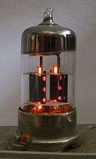
Low power triodes have a concentric construction (see drawing right), with the grid and plate as circular or oval cylinders surrounding the cathode. The cathode is a narrow metal tube down the center. Inside it is a filament called the "heater" consisting of a narrow strip of high resistance tungsten wire, which heats the cathode red-hot (800 - 1000 °C). This type is called an "indirectly heated cathode" The cathode is coated with a mixture of alkaline earth oxides such as calcium and thorium oxide which reduces its work function so it produces more electrons. The grid is constructed of a helix or screen of thin wires surrounding the cathode. The plate is a cylinder or rectangular box of sheet metal surrounding the grid. It is blackened to radiate heat and is often equipped with heat-radiating fins. The electrons travel in a radial direction, from the cathode through the grid wires to the plate. The elements are held in position by mica or ceramic insulators and are supported by stiff wires attached to the base, where the electrodes are brought out to connecting pins. A "getter", a small amount of shiny barium metal evaporated onto the inside of the glass, helps maintain the vacuum by absorbing gas released in the tube over time.
High-power triodes
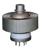
High-power triodes generally use a filament which serves as the cathode (a directly heated cathode) because the emission coating on indirectly heated cathodes is destroyed by the higher ion bombardment in power tubes. A thoriated tungsten filament is most often used, in which thorium in the tungsten forms a monolayer on the surface which increases electron emission. These generally run at higher temperatures than indirectly heated cathodes. The envelope of the tube is often made of more durable ceramic rather than glass, and all the materials have higher melting points to withstand higher heat levels produced. Tubes with plate power dissipation over about 350 W must be actively cooled or else, housed in a Silica envelope which allows for radiation cooling with anode temperatures well above 900 °C.[19] Otherwise, the plate electrode, made of heavy copper, projects through the wall of the tube and is attached to a large external finned metal heat sink which is cooled by forced air or water.
Lighthouse tubes

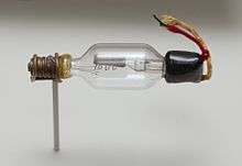
A type of low power triode for use at high (UHF) frequencies, the "lighthouse" tube has a planar construction to reduce interelectrode capacitance and lead inductance, which gives it the appearance of a "lighthouse". The disk-shaped cathode, grid and plate form planes up the center of the tube - a little like a sandwich with spaces between the layers. The cathode at the bottom is attached to the tube's pins, but the grid and plate are brought out to low inductance terminals on the upper level of the tube: the grid to a metal ring halfway up, and the plate to a metal button at the top. These are one example of "disk seal" design. Smaller examples dispense with the octal pin base shown in the illustration and rely on contact rings for all connections, including heater and D.C. cathode.
As well, high-frequency performance is limited by transit time: the time required for electrons to travel from cathode to anode. Transit time effects are complicated, but one simple effect is input conductance, also known as grid loading. At extreme high frequencies, electrons arriving at the grid may become out of phase with those departing towards the anode. This imbalance of charge causes the grid to exhibit a reactance that is much less than its low-frequency "open circuit" characteristic.
Transit time effects are reduced by reduced spacings in the tube. Tubes such as the 416B (a Lighthouse design) and the 7768 (an all-ceramic miniaturised design) are specified for operation to 4 GHz. They feature greatly reduced grid-cathode spacings in the order of 0.1 mm.
These greatly reduced grid spacings also give a much higher amplification factor than conventional axial designs. The 7768 has an amplification factor of 225, compared with 100 for the 6AV6 used in domestic radios and about the maximum possible for an axial design.
Anode-grid capacitance is not especially low in these designs. The 6AV6 anode-grid capacitance is 2 picofarads (pF), the 7768 has a value of 1.7 pF. The close electrode spacing used in microwave tubes increases capacitances, but this increase is offset by their overall reduced dimensions compared to lower-frequency tubes.
Operation


In the triode, electrons are released into the tube from the metal cathode by heating it, a process called thermionic emission. The cathode is heated red hot by a separate current flowing through a thin metal filament. In a few triodes, the filament itself is the cathode, while in most the filament heats a separate cathode electrode. Virtually all the air is removed from the tube, so the electrons can move freely. The negative electrons are attracted to the positively charged plate (anode), and flow through the spaces between the grid wires to it, creating a current through the tube from cathode to plate.
The magnitude of this current can be controlled by a voltage applied between the cathode and the grid. The grid acts like a gate for the electrons. A more negative voltage on the grid will repel some of the electrons, so fewer get through to the plate, reducing the plate current. A positive voltage on the grid will attract more electrons from the cathode, so more reach the plate, increasing the plate current. Therefore, a low power varying (AC) signal applied to the grid can control a much more powerful plate current, resulting in amplification. Variation in the grid voltage will cause identical proportional variations in the plate current. By placing a suitable load resistance in the plate circuit, the varying current will cause a varying voltage across the resistance which can be much larger than the input voltage variations, resulting in voltage gain.
The triode is a normally "on" device; and current flows to the plate with zero voltage on the grid. The plate current is progressively reduced as the grid is made more negative with respect to the cathode. Usually a constant DC voltage ("bias") is applied to the grid to set the DC current through the tube, and the varying signal voltage is superimposed on it. A sufficiently negative voltage on the grid, usually around 3-5 volts in small tubes such as the 6AV6, but as much as –130 volts in early audio power devices such as the '45, will prevent any electrons from getting through to the plate, turning off the plate current. This is called the "cutoff voltage". Since below cutoff the plate current ceases to respond to the grid voltage, the voltage on the grid must remain above the cutoff voltage for faithful (linear) amplification.
The triode is very similar in operation to the n-channel JFET; it is normally on, and progressively switched off as the grid/gate is pulled increasingly negative of the source/cathode. Cutoff voltage is equivalent to the JFET's pinch-off voltage (Vp)or VGS(off); the point at which current stops flowing entirely.
Applications
Although S.G. Brown's Type G Telephone Relay (using a magnetic "earphone" mechanism driving a carbon microphone element) was able to give power amplification and had been in use as early as 1914, it was a purely mechanical device with limited frequency range and fidelity. It was suited only to a limited range of audio frequencies - essentially voice frequencies.[20]
The triode was the first non-mechanical device to provide power gain at audio and radio frequencies, and made radio practical. Triodes are used for amplifiers and oscillators. Many types are used only at low to moderate frequency and power levels. Large water-cooled triodes may be used as the final amplifier in radio transmitters, with ratings of thousands of watts. Specialized types of triode ("lighthouse" tubes, with low capacitance between elements) provide useful gain at microwave frequencies.
Vacuum tubes are obsolete in mass-marketed consumer electronics, having been overtaken by less expensive transistor-based solid-state devices. However, more recently, vacuum tubes have been making somewhat of a comeback. Triodes increasingly continue to be used in certain performance sensitive areas such as high-end and professional audio applications, as well as in microphone preamplifiers, electric guitar amplifiers, and high-power RF amplifiers and transmitters.
Characteristics

In triode datasheets, characteristics linking the anode current (Ia) to anode voltage (Va) and grid voltage (Vg) are usually given. From here, a circuit designer can choose the operating point of the particular triode.
In the example characteristic shown on the image, if an anode voltage Va of 200 V and a grid voltage bias of -1 volt are selected, a plate (anode) current of 2.25 mA will be present (using the yellow curve on the graph). Changing the grid voltage will change the plate current; by suitable choice of a plate load resistor, amplification is obtained.
In the class-A triode amplifier, an anode resistor would be connected between the anode and the positive voltage source. For example, with Ra=10000 Ohms, the voltage drop on it would be
VRa=Ia×Ra=22.5 V if an anode current of Ia=2.25 mA is chosen.
If the input voltage amplitude (at the grid) changes from -1.5 V to -0.5 V (difference of 1 V), the anode current will change from 1.2 to 3.3 mA (see image). This will change the resistor voltage drop from 12 to 33 V (a difference of 21 V).
Since the grid voltage changes from -1.5 V to -0.5 V, and the anode resistor voltage drops from 12 to 33 V, an amplification of the signal resulted. The amplification factor is 21 - output voltage amplitude divided by input voltage amplitude.
See also
References
- ↑ Aitken, Hugh G.J. (2014). The Continuous Wave: Technology and American Radio, 1900-1932. Princeton University Press. p. 195. ISBN 1400854601.
- ↑ Fisher, David E.; Fisher, Marshall (1996). Tube: The Invention of Television. Counterpoint. p. 54. ISBN 1887178171.
- 1 2 3 Tyne, Gerald F. J. (September 1943). "The Saga of the Vacuum Tube, Part 6" (PDF). Radio News. Chicago, IL: Ziff-Davis. 30 (3): 26–28, 91. Retrieved November 30, 2016.
- 1 2 Tyne, Gerald F. J. (November 1943). "The Saga of the Vacuum Tube, Part 8" (PDF). Radio News. Chicago, IL: Ziff-Davis. 30 (5): 26–28. Retrieved November 30, 2016.
- 1 2 Anton A. Huurdeman, The Worldwide History of Telecommunications, John Wiley & Sons - 2003, page 226
- ↑ John Bray, The Communications Miracle: The Telecommunication Pioneers from Morse to the Information Superhighway, Springe - 2013, pages 64-65
- ↑ DRP 179807
- ↑ Tapan K. Sarkar (ed.) "History of wireless", John Wiley and Sons, 2006. ISBN 0-471-71814-9, p.335
- ↑ Sōgo Okamura (ed), History of Electron Tubes, IOS Press, 1994 ISBN 90-5199-145-2 page 20
- ↑ De Forest, Lee (January 1906). "The Audion; A New Receiver for Wireless Telegraphy". Trans. of the AIEE. American Institute of Electrical and Electronic Engineers. 25: 735–763. doi:10.1109/t-aiee.1906.4764762. Retrieved January 7, 2013. The link is to a reprint of the paper in the Scientific American Supplement, No. 1665, November 30, 1907, p.348-350, copied on Thomas H. White's United States Early Radio History website
- ↑ U.S. Patent 879,532, Space Telegraphy, filed January 29, 1907, issued February 18, 1908
- ↑ Hijiya, James A. (1997). Lee de Forest and the Fatherhood of Radio. Lehigh University Press. p. 77. ISBN 0934223238.
- 1 2 Okamura, Sōgo (1994). History of Electron Tubes. IOS Press. pp. 17–22. ISBN 9051991452.
- 1 2 3 Lee, Thomas H. (2004). Planar Microwave Engineering: A Practical Guide to Theory, Measurement, and Circuits. Cambridge University Press. pp. 13–14. ISBN 0521835267.
- ↑ John Bray, The Communications Miracle: The Telecommunication Pioneers from Morse to the Information Superhighway, Springe - 2013, page 64
- 1 2 Nebeker, Frederik (2009). Dawn of the Electronic Age: Electrical Technologies in the Shaping of the Modern World, 1914 to 1945. John Wiley & Sons. pp. 14–15. ISBN 0470409746.
- ↑ Hempstead, Colin; William E. Worthington (2005). Encyclopedia of 20th-Century Technology, Vol. 2. Taylor & Francis. p. 643. ISBN 1579584640.
- ↑ Armstrong, E.H. (September 1915). "Some Recent Developments in the Audion Receiver". Proceedings of the IRE. 3 (9): 215–247. doi:10.1109/jrproc.1915.216677.. Republished as Armstrong, E.H. (April 1997). "Some Recent Developments in the Audion Receiver" (PDF). Proceedings of the IEEE. 85 (4): 685–697. doi:10.1109/jproc.1997.573757.
- ↑ "TYS5-3000 R.F. Power triode data sheet" (PDF). Mullard. Retrieved 23 January 2016.
- ↑ Tyne, Gerald F.J., Saga of the Vacuum Tube, 1977, Howard W. Sams, pp 201~202
External links
| Wikimedia Commons has media related to Vacuum triodes. |
- Les lampes radio — A French page on thermionic valves. Of particular interest is the 17-minute video showing the manual production of triodes.
- Triode valve tutorial