Traveling-wave tube
A traveling-wave tube (TWT, pronounced "twit") or traveling-wave tube amplifier (TWTA, pronounced "tweeta") is a specialized vacuum tube that is used in electronics to amplify radio frequency (RF) signals in the microwave range.[1] The TWT belongs to a category of "linear beam" tubes, such as the klystron, in which the radio wave is amplified by absorbing power from a beam of electrons as it passes down the tube.[1] Although there are various types of TWT, two major categories are:[1]
- Helix TWT
- In which the radio waves interact with the electron beam while traveling down a wire helix which surrounds the beam. These have wide bandwidth, but output power is limited to a few hundred watts.[2]
- Coupled cavity TWT
- In which the radio wave interacts with the beam in a series of cavity resonators through which the beam passes. These function as narrowband power amplifiers.
A major advantage of the TWT over some other microwave tubes is its ability to amplify a wide range of frequencies, a wide bandwidth. The bandwidth of the helix TWT can be as high as two octaves, while the cavity versions have bandwidths of 10–20%.[1][2] Operating frequencies range from 300 MHz to 50 GHz.[1][2] The power gain of the tube is on the order of 40 to 70 decibels,[2] and output power ranges from a few watts to megawatts.[1][2]
TWTs account for over 50% of the sales volume of all microwave vacuum tubes.[1] They are widely used as the power amplifiers and oscillators in radar systems, communication satellite and spacecraft transmitters, and electronic warfare systems.[1]
Description
Basic TWT
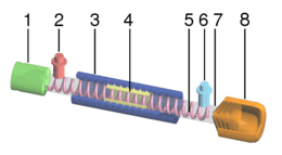
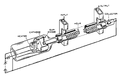
The TWT is an elongated vacuum tube with an electron gun (a heated cathode that emits electrons) at one end. A voltage applied across the cathode and anode accelerates the electrons towards the far end of the tube, and an external magnetic field around the tube focuses the electrons into a beam. At the other end of the tube the electrons strike the "collector", which returns them to the circuit.
Wrapped around the inside of the tube, just outside the beam path, is a helix of wire, typically oxygen-free copper. The RF signal to be amplified is fed into the helix at a point near the emitter end of the tube. The signal is normally fed into the helix via a waveguide or electromagnetic coil placed at one end, forming a one-way signal path, a directional coupler.
By controlling the accelerating voltage, the speed of the electrons flowing down the tube is set to be similar to the speed of the RF signal running down the helix. The signal in the wire causes a magnetic field to be induced in the center of the helix, where the electrons are flowing. Depending on the phase of the signal, the electrons will either be sped up or slowed down as they pass the windings. This causes the electron beam to "bunch up", known technically as "velocity modulation". The resulting pattern of electron density in the beam is an analog of the original RF signal.
Because the beam is passing the helix as it travels, and that signal varies, it causes induction in the helix, amplifying the original signal. By the time it reaches the other end of the tube, this process has had time to deposit considerable energy back into the helix. A second directional coupler, positioned near the collector, receives an amplified version of the input signal from the far end of the RF circuit. Attenuators placed along the RF circuit prevent the reflected wave from traveling back to the cathode.
Higher powered helix TWTs usually contain beryllium oxide ceramic as both a helix support rod and in some cases, as an electron collector for the TWT because of its special electrical, mechanical, and thermal properties.[3][4]
Comparison
There are a number of RF amplifier tubes that operate in a similar fashion to the TWT, known collectively as velocity-modulated tubes. The best known example is the klystron. All of these tubes use the same basic "bunching" of electrons to provide the amplification process, and differ largely in what process causes the velocity modulation to occur.
In the klystron, the electron beam passes through a hole in a resonant cavity which is connected to the source RF signal. The signal at the instant the electrons pass through the hole causes them to be accelerated (or decelerated). After this the faster electrons overtake the slower ones, causing the density to rise. This process ends when the mutual repulsion between the electrons causes the velocity to average out. This takes time to complete as the electrons drift down the tube, leading to their alternate name "drift tubes".
In comparison, in the TWT the acceleration is caused by the interactions with the helix along the entire length of the tube. This allows the TWT to have a very low noise output, a major advantage of the design. More usefully, this process is much less sensitive to the physical arrangement of the tube, which allows the TWT to operate over a wider variety of frequencies. TWT's are generally at an advantage when low noise and frequency variability are useful.[5][6]
Coupled-cavity TWT
Helix TWTs are limited in peak RF power by the current handling (and therefore thickness) of the helix wire. As power level increases, the wire can overheat and cause the helix geometry to warp. Wire thickness can be increased to improve matters, but if the wire is too thick it becomes impossible to obtain the required helix pitch for proper operation. Typically helix TWTs achieve less than 2.5 kW output power.
The coupled-cavity TWT overcomes this limit by replacing the helix with a series of coupled cavities arranged axially along the beam. This structure provides a helical waveguide, and hence amplification can occur via velocity modulation. Helical waveguides have very nonlinear dispersion and thus are only narrowband (but wider than klystron). A coupled-cavity TWT can achieve 60 kW output power.
Operation is similar to that of a klystron, except that coupled-cavity TWTs are designed with attenuation between the slow-wave structure instead of a drift tube. The slow-wave structure gives the TWT its wide bandwidth. A free electron laser allows higher frequencies.
Traveling-wave-tube amplifier
A TWT integrated with a regulated power supply and protection circuits is referred to as a traveling-wave-tube amplifier[7] (abbreviated TWTA and often pronounced "TWEET-uh"). It is used to produce high-power radio frequency signals. The bandwidth of a broadband TWTA can be as high as one octave, although tuned (narrowband) versions exist; operating frequencies range from 300 MHz to 50 GHz.
A TWTA consists of a traveling-wave tube coupled with its protection circuits (as in klystron) and regulated power supply electronic power conditioner (EPC), which may be supplied and integrated by a different manufacturer. The main difference between most power supplies and those for vacuum tubes is that efficient vacuum tubes have depressed collectors to recycle kinetic energy of the electrons, so the secondary winding of the power supply needs up to 6 taps of which the helix voltage needs precise regulation. The subsequent addition of a linearizer (as for inductive output tube) can, by complementary compensation, improve the gain compression and other characteristics of the TWTA; this combination is called a linearized TWTA (LTWTA, "EL-tweet-uh").
Broadband TWTAs generally use a helix TWT, and achieve less than 2.5 kW output power. TWTAs using a coupled cavity TWT can achieve 15 kW output power, but at the expense of bandwidth.
Invention, development and early use
The original design and prototype of the TWT was done by Andrei "Andy" Haeff c. 1931 while he was working as a doctoral student at the Kellogg Radiation Laboratory at Caltech. His original patent, "Device for and Method of Controlling High Frequency Currents", was filed in 1933 and granted in 1936.[8][9]
The invention of the TWT is often attributed to Rudolf Kompfner in 1942–1943. In addition, Nils Lindenblad, working at RCA (Radio Corporation of America) in the USA also filed a patent for a device in May 1940[10] that was remarkably similar to Kompfner's TWT.[11]:2 Both of these devices were improvements over Haeff's original design as they both used the then newly invented precision electron gun as the source of the electron beam and they both directed the beam down the center of the helix instead of outside of it. These configuration changes resulted in much greater wave amplification than Haeff's design as they relied on the physical principles of velocity modulation and electron bunching.[9] Kompfner developed his TWT in a British Admiralty radar laboratory during World War II.[12] His first sketch of his TWT is dated November 12, 1942, and he built his first TWT in early 1943.[11]:3[13] The TWT was later refined by Kompfner,[13] John R. Pierce,[14] and Lester M. Field at Bell Labs. Note that Kompfner's US patent, granted in 1953, does cite Haeff's previous work.[9]
By the 1950s, after further development at the Electron Tube Laboratory at Hughes Aircraft Company in Culver City, California, TWTs went into production there, and by the 1960s TWTs were also produced by such companies as the English Electric Valve Company, followed by Ferranti in the 1970s.[15][16][17]
On July 10, 1962, the first communications satellite, Telstar 1, was launched with a 2 W, 4 GHz RCA-designed TWT transponder used for transmitting RF signals to Earth stations. Syncom 2 was successfully launched into geosynchronous orbit on July 26, 1963 with two 2 W, 1850 MHz Hughes-designed TWT transponders — one active and one spare.[18][19]
Uses
TWTAs are commonly used as amplifiers in satellite transponders, where the input signal is very weak and the output needs to be high power.[20]
A TWTA whose output drives an antenna is a type of transmitter. TWTA transmitters are used extensively in radar, particularly in airborne fire-control radar systems, and in electronic warfare and self-protection systems.[21] In such applications, a control grid is typically introduced between the TWT's electron gun and slow-wave structure to allow pulsed operation. The circuit that drives the control grid is usually referred to as a grid modulator.
Another major use of TWTAs is for the electromagnetic compatibility (EMC) testing industry for immunity testing of electronic devices.
TWTAs can often be found in older (pre-1995) aviation SSR microwave transponders.
See also
- Distributed amplifier
- Magnetron
- Klystron tube
- Crossed-field amplifier
- Backward wave oscillator
- Inductive output tube
- Extended interaction oscillator
References
- 1 2 3 4 5 6 7 8 Gilmour, A. S. (2011). Klystrons, Traveling Wave Tubes, Magnetrons, Crossed-Field Amplifiers, and Gyrotrons. Artech House. pp. 317–18. ISBN 1608071855.
- 1 2 3 4 5 Whitaker, Jerry C. (2002). The RF Transmission Systems Handbook. CRC Press. pp. 8.14–8.16. ISBN 1420041134.
- ↑ 1997 Industrial Assessment of the Microwave Power Tube Industry - US Department of Defense
- ↑ Beryllium Oxide Properties
- ↑ "Traveling Wave Tube"
- ↑ "Velocity-modulated Tubes"
- ↑ John Everett (1992). Vsats: Very Small Aperture Terminals. IET. ISBN 0-86341-200-9.
- ↑ US 2064469
- 1 2 3 Copeland, Jack; Haeff, Andre A. (September 2015). "The True History of the Traveling Wave Tube". IEEE Spectrum: 38–43.
- ↑ US 2300052
- 1 2 Gilmour, A. S. (1994). Principles of traveling wave tubes. Artech House Radar Library. Boston: Artech House. pp. 2–3. ISBN 978-0-890-06720-8.
- ↑ Shulim E. Tsimring (2007). Electron beams and microwave vacuum electronics. John Wiley and Sons. p. 298. ISBN 978-0-470-04816-0.
- 1 2 Kompfner, Rudolf (1964). The Invention of the Traveling-Wave Tube. San Francisco Press.
- ↑ Pierce, John R. (1950). Traveling-Wave Tubes. D. van Nostrand Co.
- ↑ Fire Direct Web site. Accessed 2 July 2008
- ↑ "TWT - Travelling Wave Tubes". Retrieved 2008-07-08.
- ↑ Hugh Griffiths (G4CNV) (September 1980). "Travelling Wave Tube Amplifiers". RadCom. Retrieved 2015-07-15.
- ↑ Zimmerman, Robert (Fall 2000). "TELSTAR". Invention and Technology Magazinepublisher=American Heritage. 16 (2). Archived from the original on October 13, 2007. Retrieved 2 July 2008.
- ↑ Pond, Norman H. (2008). The Tube Guys. West Plains, Missouri: Russ Cochran. p. 328. ISBN 978-0-9816923-0-2. Archived from the original on June 19, 2010.
- ↑ Dennis Roddy (2006). Satellite Communications. McGraw-Hill Professional. ISBN 0-07-146298-8.
- ↑ L. Sivan (1994). Microwave Tube Transmitters. Springer. ISBN 0-412-57950-2.
Further reading
- Copeland, Jack; Haeff, Andre A. (September 2015). "The True History of the Traveling Wave Tube".
- Anderson, Carter M; (November 2015). "The Quest for the Ultimate Vacuum Tube". IEEE Spectrum;
External links
- Memorial page, with photo of John Pierce holding a TWT
- Nyquist page, with photo of Pierce, Kompfner, and Nyquist in front of TWT calculations on blackboard
- TMD Travelling Wave Tubes, Information & PDF data sheets.
- Flash animation showing the operation of a traveling wave tube (TWT) and its internal construction