Torque wrench
A torque wrench is a tool used to apply precisely a specific torque to a fastener such as a nut or bolt. It is usually in the form of a socket wrench with special internal mechanisms. It was invented by Conrad Bahr in 1918 while working for the New York City Water Department. It was designed to prevent overtightening bolts on water main and steam pipe repairs underground.
A torque wrench is used where the tightness of screws and bolts is crucial. It allows the operator to measure the torque applied to the fastener so it can be matched to the specifications for a particular application. This permits proper tension and loading of all parts. A torque wrench measures torque as a proxy for bolt tension. The technique suffers from inaccuracy due to inconsistent or uncalibrated friction between the fastener and its mating hole. Measuring bolt tension (indirectly via bolt stretch) is actually what is desired, but often torque is the only practical measurement which can be made.
Torque screwdrivers and torque wrenches have similar purposes and mechanisms.
Types
Beam

The most basic form of torque wrench consists of two beams. The first is a lever used to apply the torque to the fastener being tightened and serves also as the handle of the tool. When force is applied to the handle it will deflect predictably and proportionally with said force in accordance with Hooke's law. The second beam is only attached at one end to the wrench head and free on its other, this serves as the indicator beam. Both of these beams run parallel to each other when the tool is at rest, with the indicator beam usually on top. The indicator beam's free end is free to travel over a calibrated scale attached to the lever or handle, marked in units of torque. When the wrench is used to apply torque, the lever bends and the indicating beam stays straight. Thus the end of the indicating beam points to the magnitude of the torque that is currently being applied.[1] This type of wrench is simple, inherently accurate, and inexpensive.
The beam type torque wrench was developed in the late 1920s/early 1930s by Walter Percy Chrysler for the Chrysler Corporation and a company known as Micromatic Hone. Paul Allen Sturtevant—a sales representative for the Cedar Rapids Engineering Company at that time—was licensed by Chrysler to manufacture his invention. Sturtevant patented the torque wrench in 1938 and became the first individual to sell torque wrenches.
A more sophisticated variation of the beam type torque wrench has a dial gauge indicator on its body that can be configured to give a visual indication, or electrical indication, or both when a preset torque is reached.[2] [3]
Deflecting beam
The dual-signal deflecting beam torque wrench was patented by the Australian Warren and Brown company in 1948. [4] It employs the principle of applying torque to a deflecting beam rather than a coil spring. This is claimed to help prolong the accuracy of the wrench throughout its working life, with a greater safety margin on maximum loading and provides more consistent and accurate readings throughout the range of each wrench. The operator can both hear the signal click and see a visible indicator when the desired torque is reached. [5]
The wrench functions in the same general way as an ordinary beam torque wrench. There are two beams both connected to the head end but only one through which torque is applied. The load carrying beam is straight and runs from head to handle, it deflects when torque is applied. The other beam (indicating beam) runs directly above the deflecting beam for about half of the length then bends away to the side at an angle from the deflecting beam. The indicating beam retains its orientation and shape during operation, because of this there is relative displacement between the two beams. The deflecting beam torque wrench differs from the ordinary beam torque wrench in how it utilises this relative displacement. Attached to the deflecting beam is a scale and onto that is fitted a wedge which can be slid along the length of the scale parallel to the flexing beam, this wedge is used to set the desired torque. Directly facing this wedge is the side of the angled indicating beam. From this side protrudes a pin, which acts as a trigger for another pin, the latter pin is spring loaded, and fires out of the end of the indicating beam once the trigger pin contacts the adjustable wedge. This firing makes a loud click and gives a visual indication that the desired torque has been met. The indicator pin can be reset by simply pressing it back into the indicating beam.[5] [6]
Slipper

A slipper type torque wrench consists of a roller and cam (or similar) mechanism. The cam is attached to the driving head, the roller pushes against the cam locking it in place with a specific force which is provided by a spring (which is in many cases adjustable). If a torque is demanded which is able to defeat the holding force of the roller and spring, the wrench will slip and no torque will be applied to the bolt. A slipper torque wrench will not over tighten the fastener by continuing to apply torque beyond a predetermined limit.[7]
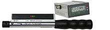
Click


A more sophisticated method of presetting torque is with a calibrated clutch mechanism. One common form uses a ball detent and spring, with the spring preloaded by an adjustable screw thread, calibrated in torque units. The ball detent transmits force until the preset torque is reached, at which point the force exerted by the spring is overcome and the ball "clicks" out of its socket. The advantage of this design is greater precision and both tangible and audible feedback on reaching the desired torque. The wrench will not start slipping once the desired torque is reached, it will only click and bend slightly at the head, the operator can continue to apply torque to the wrench without any additional action or warnings from the wrench. [8] [9] For this reason, it is important to stop applying torque as soon as the wrench gives the click sound.
A number of variations of this design exist for different applications and different torque ranges. A modification of this design is used in some drills to prevent gouging the heads of screws while tightening them. (The drill will start slipping once the desired torque is reached).
"No-hub" wrench
These are specialised torque wrenches used by plumbers to tighten the clamping bands on hubless soil pipe couplings. They are usually T-handled wrenches with a one-way combination ratchet and clutch. They are preset to a fixed torque designed to adequately secure the coupling but insufficient to damage it. [10]
Electronic torque wrenches
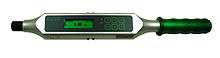
With electronic (indicating) torque wrenches, measurement is by means of a strain gauge attached to the torsion rod. The signal generated by the transducer is converted to the required unit of torque (e.g. N·m or lbf·ft) and shown on the digital display. A number of different joints (measurement details or limit values) can be stored. These programmed limit values are then permanently displayed during the tightening process by means of LEDs or the display. At the same time, this generation of torque wrenches can store all the measurements made in an internal readings memory. This readings memory can then be easily transferred to a PC via the interface (RS232) or printed straight to a printer. A popular application of this kind of torque wrench is for in-process documentation or quality assurance purposes. Typical accuracy level would be +/- 0.5% to 4%.
Programmable electronic torque / angle wrenches
Torque measurement is conducted in the same way as with an electronic torque wrench but the tightening angle from the snug point or threshold is also measured. The angle is measured by an angle sensor or electronic gyroscope. The angle measurement process enables joints which have already been tightened to be recognised. The inbuilt readings memory enables measurements to be statistically evaluated. Tightening curves can be analysed using the software via the integrated tightening-curve system (force/path graph). This type of torque wrench can also be used to determine breakaway torque, prevail torque and the final torque of a tightening job. Thanks to a special measuring process, it is also possible to display the yield point (yield controlled tightening). This design of torque wrench is highly popular with automotive manufacturers for documenting tightening processes requiring both torque and angle control because, in these cases, a defined angle has to be applied to the fastener on top of the prescribed torque (e.g. 50 N·m or 37 lbf·ft + 90° - here the 50 N·m or 37 lbf·ft means the snug point/threshold and +90° indicates that an additional angle has to be applied after the threshold).
Saltus-Werk Max Forst GmbH applied in 1995 for an international patent for the first electronic torque wrench with angle measurement which did not require a reference arm.
Mechatronic torque wrenches
Torque measurement is achieved in the same way as with a click-type torque wrench but, at the same time, the torque is measured as a digital reading (click and final torque) as with an electronic torque wrench. This is, therefore, a combination of electronic and mechanical measurements. All the measurements are transferred and documented via wireless data transmission. Users will know they have achieved the desired torque setting when the wrench "beeps."
Torque wrench standardisation
ISO
The International Organization for Standardization maintains standard ISO 6789. This standard covers the construction and calibration of hand operated torque tools. They define two types of torque tool encompassing twelve classes, these are given by the table below. Also given is the percentage allowable deviation from the desired torque. [11] [12]
| Torque wrench types | Torque wrench tolerance | |||
|---|---|---|---|---|
| Type | Class | Description | ≤ 10 Nm | >10 Nm |
| Type 1: Indicating | Class A | Wrench with torsion or flexing bar | ±6% | |
| Class B | Wrench with rigid body and indicator | ±6% | ±4% | |
| Class C | Wrench with rigid body and electronic measurement | ±6% | ±4% | |
| Class D | Screwdriver with indicator | ±6% | ||
| Class E | Screwdriver with electronic measurement | ±6% | ±4% | |
| Type 2: Setting | Class A | Adjustable wrench with indicator | ±6% | ±4% |
| Class B | Fixed torque wrench | ±6% | ±4% | |
| Class C | Adjustable wrench without indicator | ±6% | ±4% | |
| Class D | Adjustable screwdriver with indicator | ±6% | ||
| Class E | Fixed screwdriver | ±6% | ||
| Class F | Adjustable screwdriver without indicator | ±6% | ||
| Class G | Adjustable wrench with flexing bar and indicator | ±6% | ||
The ISO standard also states that even when overloaded by 25% of the maximum rating, the tool should remain reliably usable after being re-calibrated. Re-calibration for tools used within their specified limits should occur after 5000 cycles of torquing or 12 months, whichever is soonest. In cases where the tool is in use in an organisation which has its own quality control procedures, then the calibration schedule can be arranged according to company standards.[11][12]
Tools should be marked with their torque range and the unit of torque as well as the direction of operation for unidirectional tools and the maker's mark. If a calibration certificate is provided, the tool must be marked with a serial number that matches the certificate or a calibration laboratory should give the tool a reference number corresponding with the tool's calibration certificate.[11][12]
ASME
The American Society of Mechanical Engineers maintains standard ASME B107.300. This standard has the same type designation as the ISO standard with the addition of the type 3, (limiting) torque tool. This type will release the drive once the desired torque is met so that no more torque can be applied. This standard, however, uses different class designations within each type as well as additional style and design variants within each class. The standard also separates manual and electronic tools into different sections and designations. The ASME and ISO standards cannot be considered compatible. The table below gives some of the types and tolerances specified by the standard for manual torque tools. [13] [14]
| Torque wrench types | Torque wrench tolerance | |||
|---|---|---|---|---|
| Type | Class | Style | <20% max rating | 20-100% max rating |
| Type 1: Indicating | Class A: Deflecting beam | Style 1: Plain scale | ±0.8% | ±4% |
| Style 2: Scale with signal | ||||
| Style 3: Scale with memory | ||||
| Class B: Deflecting beam, changeable head | Style 1: Plain scale | |||
| Style 2: Scale with signal | ||||
| Style 3: Scale with memory | ||||
| Class C: Rigid housing | Style 1: Plain scale | |||
| Style 2: Scale with signal | ||||
| Style 3: Scale with memory | ||||
| Class D: Rigid housing, changeable head | Style 1: Plain scale | |||
| Style 2: Scale with signal | ||||
| Style 3: Scale with memory | ||||
| Class E: Screwdriver, indicating | Style 1: Plain scale | |||
| Style 2: Scale with signal | ||||
| Type 2: Setting[note 1] | Class A: With graduation | Style 1: Without ratchet | ±0.8% | ±4% |
| Style 2: With ratchet | ±0.8% | ±4% | ||
| Style 3: Changeable head | ±0.8% | ±4% | ||
| Style 4: Flexible head with ratchet | See standard | |||
| Class B: Without graduation | Style 1: Without ratchet | ±0.8% | ±4% | |
| Style 2: With ratchet | ±0.8% | ±4% | ||
| Style 3: Changeable head | ±0.8% | ±4% | ||
| Style 4: Flexible head with ratchet | See standard | |||
| Type 3: Limiting | Class A: Screwdriver | Style 1: Without graduation | ±1.2% | ±4% |
| Style 2: With graduation | ||||
| Class B: T handle | Style 1: Without graduation | |||
| Style 2: With graduation | ||||
Tools should be marked with the model number of the tool, the unit of torque and the maker's mark. For unidirectional tools the word "TORQUES" or "TORQUE" and the direction of operation must also be marked.[13]
Using torque wrenches
Precision
Click type torque wrenches are precise when properly calibrated—however the more complex mechanism can result in loss of calibration sooner than the beam type, where there is little to no malfunction, (however the thin indicator rod can be accidentally bent out of true). Beam type torque wrenches are impossible to use in situations where the scale cannot be directly read—and these situations are common in automotive applications. The scale on a beam type wrench is prone to parallax error, as a result of the large distance between indicator arm and scale (on some older designs). There is also the issue of increased user error with the beam type—the torque has to be read at every use and the operator must use caution to apply loads only at the floating handle's pivot point. Dual-beam or "flat" beam versions reduce the tendency for the pointer to rub, as do low-friction pointers.
Extensions
The use of cheater bars that extend from the handle end can damage the wrench, so only manufacturer specified equipment should be used.[15]

Using handle or socket extensions requires no adjustment of the torque setting.[16]
Using a crow's foot or similar extension requires the use of the following equation:[16][17][18]

using a combination of handle and crow's foot extensions requires the use of the following equation:[16]

where:
- is the wrench indicated torque (setting torque),
- is the desired torque,
- is the length of the torque wrench, from the handle to the centre of the head,
- is the length of the crow's foot extension, from the centre of the torque wrench head to the centre line of the bolt,
- is the length of the handle extension, from the extension end to the torque wrench handle.


These equations only apply if the extension is colinear with the length of the torque wrench. In other cases, the distance from the torque wrench's head to the bolt's head, as if it were in line, should be used. If the extension is set at 90° then no adjustment is required. These methods are not recommended except for extreme circumstances.[16]
Storage
For click (or other micrometer) types, when not in use, the force acting on the spring should be removed by setting the scale to its minimum rated value in order to prevent permanent set in the spring.[19][20] Never set a micrometer style torque wrench to zero as the internal mechanism requires a small amount of tension in order to prevent components shifting and reduction of accuracy.[19] If a micrometer tool has been stored with the setting above 20% the tool should be set to 50% of full scale and exercised at least FIVE times before being used. In the case of the beam type, there is no strain on the component that provides the reference force except when it is in use, therefore, accuracy is inherent.
Calibration
As with any precision tool, torque wrenches should be periodically re-calibrated. As previously stated, according to ISO standards calibration should happen every 5000 operations or every year, whichever comes first.[11][12] It is possible that torque wrenches can fall up to 10% out of calibration in the first year of use.[14]
Calibration, when performed by a specialist service which follows ISO standards, follows a specific process and constraints. The operation requires specialist torque wrench calibration equipment with an accuracy of ±1% or better. The temperature of the area where calibration is being performed should be between 18 °C and 28 °C with no more than a 1 °C fluctuation and the relative humidity should not exceed 90%.[11]
Before any calibration work can be done the tool should be preloaded and torqued without measure according to its type. The tool is then connected to the tester and force is applied to the handle (at no more than 10° from perpendicular) for values of 20%, 60% and 100% of the maximum torque and repeated according to their class. The force should be applied slowly and without jerky or irregular motion. The table below gives more specifics regarding the pattern of testing for each class of torque wrench.[11][12]
| Type | Class | Pre-calibration | Calibration procedure |
|---|---|---|---|
| Type 1 | All classes | Preload once at the highest certified value | 5 measurements in a row for all values |
| Type 2 | Class A | Preload five times at the highest certified value | 5 measurements in a row for all values |
| Class B | 5 measurements at nominal value | ||
| Class C | 10 measurements in a row for all values | ||
| Class D | 5 measurements in a row for all values | ||
| Class E | 5 measurements at nominal value | ||
| Class F | 10 measurements in a row for all values | ||
| Class G | 5 measurements in a row for all values |
While professional calibration is recommended, for some people it would be out of their means. It is possible to calibrate a torque wrench in the home shop or garage. The process generally requires that a certain mass is attached to a lever arm and the torque wrench is set to the appropriate torque to lift said weights. The error within the tool can be calculated and the tool may be able to be altered or any work done adjusted for this error. [21] [22] [23]
See also
Notes
- ↑ ASME Type 2 is somewhat complicated and cannot be elaborated on in depth without the table becoming too large for the article.
References
- ↑ US 2231240, Zimmerman Herman W, "Torque measuring wrench", published Feb 11, 1941
- ↑ US 2167720, Willard C Kress, "Torque-indicating wrench", published Aug 1, 1939
- ↑ "DIAL TORQUE WRENCH REPAIR, MAINTENANCE AND TROUBLESHOOTING MANUAL" (PDF). CDI Torque Products. 2002.
- ↑ "Warren & Brown company history". Warren & Brown.
- 1 2 "Warren & Brown Precision Tools Catalogue" (PDF). Warren & Brown.
- ↑ "Deflecting beam torque wrench operating instructions" (PDF). Kincrome Professional Quality Tools.
- ↑ US 1860871, Wilfred A Pouliot, "Safety wrench", published May 31, 1932
- ↑ Tegger. "How does a torque wrench work?". "The Unofficial Honda / Acura Usenet FAQ".
- ↑ US 4485703, Bosko Grabovac & Ivan Vuceta, "Torque wrench", published Dec 4, 1984
- ↑ "Raptor No-Hub Torque Wrenches" (PDF). "Raptor tools".
- 1 2 3 4 5 6 ISO6789 - Assembly tools for screws and nuts. Hand torque tools. Requirements and test methods for design conformance testing, quality conformance testing and recalibration procedure. International Organization for Standardization. 2003.
- 1 2 3 4 5 Sofia. "Torque Wrench Calibration Services". Calibrate.co.uk.
- 1 2 ASME B107.300-2010 (Incorporation of ASME B107.14, B107.28, and B107.29) Torque Instruments. The American Society of Mechanical Engineers. 2010.
- 1 2 Warren Brown; Scott Hamilton; An Nguyen; Tom Smith (July 17–21, 2011). Field Calibration and Accuracy of Torque Wrenches. ASME 2011 Pressure Vessels & Piping Division Conference. The American Society of Mechanical Engineers.
- ↑ "Premium and Standard Manual Torque Wrenches Pre-Set and Adjustable" (PDF). ASG Jergens, Inc.
- 1 2 3 4 Boeing 737-200 maintenance manuals. Wikileaks. 20. 2007. pp. 202–203.
- ↑ "Torque Wrench Extension Calculator". Norbar Torque.
- ↑ "CROWFOOT ADAPTERS". Belknap Inc.
- 1 2 "The ten things you should know about your torque wrench". Norbar Torque. 2015.
- ↑ "Proper Torque Wrench Use and maintenance (Technical reference)" (PDF). Snap-on Tools. 2008.
- ↑ Various. "How to Calibrate a Torque Wrench". wikiHow. wikiHow.
- ↑ Aubrey Ivy. "How to Calibrate a Torque Wrench". Helicopter Maintenance Magazine.
- ↑ Sleepy Gomez. "How-To Calibrate A Torque Wrench". rcramer.com.
External links
| Wikimedia Commons has media related to Torque wrenches. |
- Measurement of Torque Wrench Accuracy
- Internal components and accessories of a torque wrench
- How to use a torque wrench